EP0366920A1 - Scheibe für Bremse oder Kupplung - Google Patents
Scheibe für Bremse oder Kupplung Download PDFInfo
- Publication number
- EP0366920A1 EP0366920A1 EP89117472A EP89117472A EP0366920A1 EP 0366920 A1 EP0366920 A1 EP 0366920A1 EP 89117472 A EP89117472 A EP 89117472A EP 89117472 A EP89117472 A EP 89117472A EP 0366920 A1 EP0366920 A1 EP 0366920A1
- Authority
- EP
- European Patent Office
- Prior art keywords
- discs
- brake
- rotor
- disc
- axially
- Prior art date
- Legal status (The legal status is an assumption and is not a legal conclusion. Google has not performed a legal analysis and makes no representation as to the accuracy of the status listed.)
- Granted
Links
- 239000012530 fluid Substances 0.000 claims description 3
- 238000001816 cooling Methods 0.000 abstract description 2
- 125000006850 spacer group Chemical group 0.000 description 6
- 230000000712 assembly Effects 0.000 description 1
- 238000000429 assembly Methods 0.000 description 1
- 238000007664 blowing Methods 0.000 description 1
- 239000002783 friction material Substances 0.000 description 1
- 238000007789 sealing Methods 0.000 description 1
Images

Classifications
-
- F—MECHANICAL ENGINEERING; LIGHTING; HEATING; WEAPONS; BLASTING
- F16—ENGINEERING ELEMENTS AND UNITS; GENERAL MEASURES FOR PRODUCING AND MAINTAINING EFFECTIVE FUNCTIONING OF MACHINES OR INSTALLATIONS; THERMAL INSULATION IN GENERAL
- F16D—COUPLINGS FOR TRANSMITTING ROTATION; CLUTCHES; BRAKES
- F16D55/00—Brakes with substantially-radial braking surfaces pressed together in axial direction, e.g. disc brakes
- F16D55/24—Brakes with substantially-radial braking surfaces pressed together in axial direction, e.g. disc brakes with a plurality of axially-movable discs, lamellae, or pads, pressed from one side towards an axially-located member
- F16D55/26—Brakes with substantially-radial braking surfaces pressed together in axial direction, e.g. disc brakes with a plurality of axially-movable discs, lamellae, or pads, pressed from one side towards an axially-located member without self-tightening action
- F16D55/36—Brakes with a plurality of rotating discs all lying side by side
- F16D55/38—Brakes with a plurality of rotating discs all lying side by side mechanically actuated
-
- F—MECHANICAL ENGINEERING; LIGHTING; HEATING; WEAPONS; BLASTING
- F16—ENGINEERING ELEMENTS AND UNITS; GENERAL MEASURES FOR PRODUCING AND MAINTAINING EFFECTIVE FUNCTIONING OF MACHINES OR INSTALLATIONS; THERMAL INSULATION IN GENERAL
- F16D—COUPLINGS FOR TRANSMITTING ROTATION; CLUTCHES; BRAKES
- F16D55/00—Brakes with substantially-radial braking surfaces pressed together in axial direction, e.g. disc brakes
- F16D55/24—Brakes with substantially-radial braking surfaces pressed together in axial direction, e.g. disc brakes with a plurality of axially-movable discs, lamellae, or pads, pressed from one side towards an axially-located member
- F16D55/26—Brakes with substantially-radial braking surfaces pressed together in axial direction, e.g. disc brakes with a plurality of axially-movable discs, lamellae, or pads, pressed from one side towards an axially-located member without self-tightening action
- F16D55/36—Brakes with a plurality of rotating discs all lying side by side
- F16D55/40—Brakes with a plurality of rotating discs all lying side by side actuated by a fluid-pressure device arranged in or one the brake
-
- F—MECHANICAL ENGINEERING; LIGHTING; HEATING; WEAPONS; BLASTING
- F16—ENGINEERING ELEMENTS AND UNITS; GENERAL MEASURES FOR PRODUCING AND MAINTAINING EFFECTIVE FUNCTIONING OF MACHINES OR INSTALLATIONS; THERMAL INSULATION IN GENERAL
- F16D—COUPLINGS FOR TRANSMITTING ROTATION; CLUTCHES; BRAKES
- F16D59/00—Self-acting brakes, e.g. coming into operation at a predetermined speed
- F16D59/02—Self-acting brakes, e.g. coming into operation at a predetermined speed spring-loaded and adapted to be released by mechanical, fluid, or electromagnetic means
-
- F—MECHANICAL ENGINEERING; LIGHTING; HEATING; WEAPONS; BLASTING
- F16—ENGINEERING ELEMENTS AND UNITS; GENERAL MEASURES FOR PRODUCING AND MAINTAINING EFFECTIVE FUNCTIONING OF MACHINES OR INSTALLATIONS; THERMAL INSULATION IN GENERAL
- F16D—COUPLINGS FOR TRANSMITTING ROTATION; CLUTCHES; BRAKES
- F16D65/00—Parts or details
- F16D65/02—Braking members; Mounting thereof
- F16D65/12—Discs; Drums for disc brakes
- F16D65/123—Discs; Drums for disc brakes comprising an annular disc secured to a hub member; Discs characterised by means for mounting
-
- F—MECHANICAL ENGINEERING; LIGHTING; HEATING; WEAPONS; BLASTING
- F16—ENGINEERING ELEMENTS AND UNITS; GENERAL MEASURES FOR PRODUCING AND MAINTAINING EFFECTIVE FUNCTIONING OF MACHINES OR INSTALLATIONS; THERMAL INSULATION IN GENERAL
- F16D—COUPLINGS FOR TRANSMITTING ROTATION; CLUTCHES; BRAKES
- F16D65/00—Parts or details
- F16D65/02—Braking members; Mounting thereof
- F16D65/12—Discs; Drums for disc brakes
- F16D65/128—Discs; Drums for disc brakes characterised by means for cooling
-
- F—MECHANICAL ENGINEERING; LIGHTING; HEATING; WEAPONS; BLASTING
- F16—ENGINEERING ELEMENTS AND UNITS; GENERAL MEASURES FOR PRODUCING AND MAINTAINING EFFECTIVE FUNCTIONING OF MACHINES OR INSTALLATIONS; THERMAL INSULATION IN GENERAL
- F16D—COUPLINGS FOR TRANSMITTING ROTATION; CLUTCHES; BRAKES
- F16D55/00—Brakes with substantially-radial braking surfaces pressed together in axial direction, e.g. disc brakes
- F16D2055/0004—Parts or details of disc brakes
- F16D2055/0058—Fully lined, i.e. braking surface extending over the entire disc circumference
-
- F—MECHANICAL ENGINEERING; LIGHTING; HEATING; WEAPONS; BLASTING
- F16—ENGINEERING ELEMENTS AND UNITS; GENERAL MEASURES FOR PRODUCING AND MAINTAINING EFFECTIVE FUNCTIONING OF MACHINES OR INSTALLATIONS; THERMAL INSULATION IN GENERAL
- F16D—COUPLINGS FOR TRANSMITTING ROTATION; CLUTCHES; BRAKES
- F16D2121/00—Type of actuator operation force
- F16D2121/02—Fluid pressure
- F16D2121/12—Fluid pressure for releasing a normally applied brake, the type of actuator being irrelevant or not provided for in groups F16D2121/04 - F16D2121/10
Definitions
- This invention relates to air cooled disc brakes in which the brake is applied by a spring and released by air pressure or vise versa e.g. the brake is applied by air and released by springs. It will appreciated by those skilled in the art that the invention in its broader sense may be applicable to any such disc type brake or clutch or torque transmitting device.
- Torque transmitting devices of the disc type are known in the art and generally comprise an external housing which carries and positions annular axially moveable and fixed reaction members having a disc therebetween.
- U.S. Patent No. 3,398,822 to Eakin and 4,609,076 to Collins disclose air cooled spring applied brakes or clutches which are air released by pressurization of a pressure chamber to axially move an end plate and pressure plate to overcome the force of the springs.
- the brake disc in these patents is provided with a spline coacting with an externally splined hub. Naturally, the spline connection between the brake disc and the hub permits the brake disc to slide axially along the hub but necessarily restricts the circulation of air between the brake discs and the pressure plates.
- Another object of the invention is to provide a torque transmitting device in which means for blowing air between the rotor and reaction discs are formed integrally with spline means removably attached to the radially inner portion of the rotor discs.
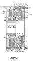
- the spring applied brake 10 includes one or more annular radially disposed rotor or rotatable disc assemblies 11 having discs 12 which are spined to a hub 13 for rotation in unison therewith but mounted for limited axial movement along the hub 13.
- a hub 13 is keyed, welded, or otherwise secured to the shaft (not shown).
- the brake assembly 10 also has a non-rotating structure which includes a rigid, fixed assembly 19 and a rigid axially moveable assembly 20.
- the axially fixed assembly 19 includes a fixed spring housing 23 and a fixed reaction disc member 21 rigidly mounted to a stationary support S by suitable fasteners.
- the disc 21 and spring housing 23 are secured together by the studs or bolts 24 passing through the spacer tubes 25 and also through a hole 26 in the spring housing 23.
- the holes 26, the spacer tubes 25, and studs 24 are circumferentially spaced apart at the radially outer periphery of the housing 23.
- the ends of the spacer tubes 25 bear against the axially facing surfaces of the disc 21 and the spring housing 23 and the studs 24 secure the tubes 25 to the disc 21 and spring housing 23 to form an assembly 19.
- a stator brake disc 22 extends radially between the rotor discs 12 and is provided with a plurality of holes at its outer periphery through which the spacer tubes 25 extend.
- the axially movable assembly 20 includes a pressure plate 27, which is secured to the cylinder member 28 by the studs or bolts 29 passing through holes 34 in the plate 27 and in the spacer tubes 30 which are circumferentially spaced apart at the radially outer periphery thereof.
- the studs 29 pass through holes in the cylinder member 28 and are secured by the nuts 31.
- the studs 29 and tubes 30 also pass through slots or gaps in the periphery of the spring housing 23.
- the movable assembly 20 is thus axially slideable a limited distance relative to the axial fixed assembly 19 with the assembly 20 slideable through holes in the pressure plate 27.
- the movable assembly 20 is supported for axial movement by the annular radially inner facing surface of the spring housing 23 slideably supported on the annular radially outer facing surfaces 42 of the cylinder member 28.
- the axially moveable assembly 20 is normally biased to the left of Fig. 1, by a plurality of springs 35 so that the pressure plate 27 bears against the friction disc 18.
- One end of each of the springs 35 is positioned within a depression 36 in the pressure plate 27.
- the other end of each of the springs 35 surrounds a projection 37 in the spring housing.
- Each of the projections 37, the depressions 36 and the springs 35 are of course axially aligned and are located radially inwardly of the respective studs 24 and tubes 25 as well as the studs 29 and spacer tubes 30.
- the brake is released by injecting a pressurized fluid into the pressure chamber 38 defined by the annular face 40 of the spring housing 23 having suitable radially inner and outer seals 41 in sealing engagement with the radially facing surfaces 42 and the annular axially facing end surface 43 formed in the cylinder member 28.
- pressurized fluid is injected through the orifices 39 into the chamber 38, the axial moveable assembly 20 is moved to the right of Fig. 1 so that the pressure plate 27 thereof is moved a slight distance away from the friction disc 18, thus compressing the springs 35 and releasing the brake.
- the brake disc 12 will move a slight distance along the hub 13 so that braking forces are relieved between the fixed reaction disc 21 and the friction disc 18.
- each of the rotor discs 12 is mounted on the hub 13 for limited axial movement.
- each rotor disc 12 is secured by fasteners 45 to a radial flange 46 formed on the gear or spline member 44.
- Spline 47 on the member 44 meshes with the spline 48 on the hub 13 to permit limited axial movement of the rotor discs 12 relative to the hub.
- the radial outer periphery of the radial flange 46 is provided with semicircular grooves 49 extending axially of the gear 44.
- a groove 49 is positioned between each pair of fasteners 45.
- the grooves 49 forms radially extending arcuate walls or vanes 50 which positively impell air radially outwardly between the friction shoes 18 and the fixed discs 22 and 27.
- Each of the rotor discs 12 is provided with axial extending holes 51 preferably of a number equal to the number of grooves 49.
- the holes 51 are each axially aligned with a groove 49.
Landscapes
- Engineering & Computer Science (AREA)
- General Engineering & Computer Science (AREA)
- Mechanical Engineering (AREA)
- Physics & Mathematics (AREA)
- Electromagnetism (AREA)
- Braking Arrangements (AREA)
Applications Claiming Priority (2)
| Application Number | Priority Date | Filing Date | Title |
|---|---|---|---|
| US07/263,840 US4863000A (en) | 1988-10-28 | 1988-10-28 | Brake or clutch disc assembly |
| US263840 | 1988-10-28 |
Publications (2)
| Publication Number | Publication Date |
|---|---|
| EP0366920A1 true EP0366920A1 (de) | 1990-05-09 |
| EP0366920B1 EP0366920B1 (de) | 1993-10-13 |
Family
ID=23003452
Family Applications (1)
| Application Number | Title | Priority Date | Filing Date |
|---|---|---|---|
| EP89117472A Expired - Lifetime EP0366920B1 (de) | 1988-10-28 | 1989-09-21 | Scheibe für Bremse oder Kupplung |
Country Status (6)
| Country | Link |
|---|---|
| US (1) | US4863000A (de) |
| EP (1) | EP0366920B1 (de) |
| JP (1) | JP2733343B2 (de) |
| CA (1) | CA1313356C (de) |
| DE (1) | DE68909887T2 (de) |
| ES (1) | ES2045324T3 (de) |
Cited By (3)
| Publication number | Priority date | Publication date | Assignee | Title |
|---|---|---|---|---|
| WO1998001681A1 (en) * | 1996-07-05 | 1998-01-15 | Chr. Mayr Gmbh & Co. Kg | Electromagnetically releasable friction safety brake |
| WO2005111456A1 (de) * | 2004-05-11 | 2005-11-24 | Knorr-Bremse Systeme für Nutzfahrzeuge GmbH | Bremsscheiben-nabenanordnung mit verschieblicher bremsscheibe |
| DE102022106270A1 (de) | 2022-03-17 | 2023-09-21 | Schaeffler Technologies AG & Co. KG | Bremsvorrichtung für eine elektrische Achsantriebsvorrichtung sowie elektrische Achsantriebsvorrichtung mit einer Bremsvorrichtung |
Families Citing this family (17)
| Publication number | Priority date | Publication date | Assignee | Title |
|---|---|---|---|---|
| JP2815467B2 (ja) * | 1990-06-29 | 1998-10-27 | 松下電器産業株式会社 | ディジタル映像信号記録再生装置及び記録再生方法 |
| US5439081A (en) * | 1994-08-31 | 1995-08-08 | Glass; Thomas V. | Compressed coolant hydraulic brake rotor |
| US6006660A (en) * | 1998-08-12 | 1999-12-28 | The Minster Machine Company | Segmented drive disk for a mechanical press |
| GB2340563A (en) | 1998-08-15 | 2000-02-23 | T & N Technology Ltd | Disc brake |
| GB2340561A (en) | 1998-08-15 | 2000-02-23 | T & N Technology Ltd | Disc brake |
| GB2340564A (en) | 1998-08-15 | 2000-02-23 | T & N Technology Ltd | Disc brake |
| GB9817741D0 (en) * | 1998-08-15 | 1998-10-14 | T & N Technology Ltd | Disc brake system |
| US6419056B1 (en) * | 1998-10-29 | 2002-07-16 | Aircraft Braking Systems Corp. | Apparatus for aircraft brake thermal management |
| DE19859616C2 (de) * | 1998-12-23 | 2003-10-16 | Daimler Chrysler Ag | Bremseinheit mit einem Reibring aus einem keramischen Werkstoff |
| US6349800B1 (en) * | 2000-02-07 | 2002-02-26 | Shimano Inc. | Bicycle disc brake assembly |
| GB2361973A (en) | 2000-05-05 | 2001-11-07 | Federal Mogul Brake Syst Ltd | Method and apparatus for mounting a disc brake |
| GB0018154D0 (en) * | 2000-07-25 | 2000-09-13 | Federal Mogul Brake Systems Li | Apparatus and method for controlling a braking system |
| US7255208B2 (en) * | 2004-02-13 | 2007-08-14 | Honeywell International Inc. | Aircraft brake wheel heat shield |
| US8813936B2 (en) * | 2008-07-25 | 2014-08-26 | Eaton Corporation | Force transmitting assembly |
| US8800726B2 (en) | 2012-02-10 | 2014-08-12 | Eaton Corporation | Dual-rotor force transmitting assembly |
| US8919514B2 (en) | 2012-03-28 | 2014-12-30 | Eaton Corporation | Floating housing force transmitting assembly |
| EP2949959B1 (de) * | 2014-05-30 | 2018-07-04 | Eaton Corporation | Scheibenbremsenbaugruppe und Verfahren zur Herstellung davon |
Citations (6)
| Publication number | Priority date | Publication date | Assignee | Title |
|---|---|---|---|---|
| FR1113195A (fr) * | 1954-10-25 | 1956-03-26 | Perfectionnements aux mécanismes à disques tels que freins et embrayages | |
| FR1135583A (fr) * | 1955-11-08 | 1957-04-30 | Rech S Etudes | Frein hydraulique à disque avec commande de secours intégrée |
| GB954421A (en) * | 1959-04-22 | 1964-04-08 | Girling Ltd | Improvements relating to brakes |
| US3335834A (en) * | 1964-05-27 | 1967-08-15 | May Pressenbau G M B H | Coupling with air cooled friction discs |
| US3398822A (en) * | 1966-05-27 | 1968-08-27 | Eaton Yale & Towne | Frictional wear element and springapplied brake or clutch embodying same |
| US4609076A (en) * | 1983-09-01 | 1986-09-02 | Eaton Corporation | Spring engaged fluid released multi-disc brake assembly |
Family Cites Families (4)
| Publication number | Priority date | Publication date | Assignee | Title |
|---|---|---|---|---|
| US2827142A (en) * | 1954-03-16 | 1958-03-18 | Twin Disc Clutch Co | Multiple disc clutch with releasing and cooling means |
| GB1235168A (en) * | 1967-09-27 | 1971-06-09 | Frankl & Kirchner | Improvements relating to electromagnetic clutches or brakes |
| US4078637A (en) * | 1976-05-07 | 1978-03-14 | Horton Manufacturing Co. Inc. | Fluid disengaged and spring urged brake |
| US4049085A (en) * | 1976-08-10 | 1977-09-20 | Safety Racing Equipment, Incorporated | Caliper brake with assembly for rotor attachment to hub |
-
1988
- 1988-10-28 US US07/263,840 patent/US4863000A/en not_active Expired - Lifetime
-
1989
- 1989-09-21 EP EP89117472A patent/EP0366920B1/de not_active Expired - Lifetime
- 1989-09-21 ES ES89117472T patent/ES2045324T3/es not_active Expired - Lifetime
- 1989-09-21 DE DE68909887T patent/DE68909887T2/de not_active Expired - Fee Related
- 1989-09-21 CA CA000612420A patent/CA1313356C/en not_active Expired - Fee Related
- 1989-10-27 JP JP1278746A patent/JP2733343B2/ja not_active Expired - Fee Related
Patent Citations (6)
| Publication number | Priority date | Publication date | Assignee | Title |
|---|---|---|---|---|
| FR1113195A (fr) * | 1954-10-25 | 1956-03-26 | Perfectionnements aux mécanismes à disques tels que freins et embrayages | |
| FR1135583A (fr) * | 1955-11-08 | 1957-04-30 | Rech S Etudes | Frein hydraulique à disque avec commande de secours intégrée |
| GB954421A (en) * | 1959-04-22 | 1964-04-08 | Girling Ltd | Improvements relating to brakes |
| US3335834A (en) * | 1964-05-27 | 1967-08-15 | May Pressenbau G M B H | Coupling with air cooled friction discs |
| US3398822A (en) * | 1966-05-27 | 1968-08-27 | Eaton Yale & Towne | Frictional wear element and springapplied brake or clutch embodying same |
| US4609076A (en) * | 1983-09-01 | 1986-09-02 | Eaton Corporation | Spring engaged fluid released multi-disc brake assembly |
Cited By (7)
| Publication number | Priority date | Publication date | Assignee | Title |
|---|---|---|---|---|
| WO1998001681A1 (en) * | 1996-07-05 | 1998-01-15 | Chr. Mayr Gmbh & Co. Kg | Electromagnetically releasable friction safety brake |
| US6202804B1 (en) | 1996-07-05 | 2001-03-20 | Chr. Mayr Gmbh & Co. Kg | Electromagnetically releasable friction safety brake |
| WO2005111456A1 (de) * | 2004-05-11 | 2005-11-24 | Knorr-Bremse Systeme für Nutzfahrzeuge GmbH | Bremsscheiben-nabenanordnung mit verschieblicher bremsscheibe |
| US7374024B2 (en) | 2004-05-11 | 2008-05-20 | Knorr-Bremse Systeme Fuer Nutzfahrzeuge Gmbh | Brake disc/hub assembly with displaceable brake discs |
| EP1747385B2 (de) † | 2004-05-11 | 2013-10-02 | KNORR-BREMSE Systeme für Nutzfahrzeuge GmbH | Bremsscheiben-nabenanordnung mit verschieblicher bremsscheibe |
| DE102022106270A1 (de) | 2022-03-17 | 2023-09-21 | Schaeffler Technologies AG & Co. KG | Bremsvorrichtung für eine elektrische Achsantriebsvorrichtung sowie elektrische Achsantriebsvorrichtung mit einer Bremsvorrichtung |
| DE102022106270B4 (de) * | 2022-03-17 | 2025-01-09 | Schaeffler Technologies AG & Co. KG | Bremsvorrichtung für eine elektrische Achsantriebsvorrichtung sowie elektrische Achsantriebsvorrichtung mit einer Bremsvorrichtung |
Also Published As
| Publication number | Publication date |
|---|---|
| JPH02173429A (ja) | 1990-07-04 |
| DE68909887T2 (de) | 1994-05-19 |
| CA1313356C (en) | 1993-02-02 |
| DE68909887D1 (de) | 1993-11-18 |
| EP0366920B1 (de) | 1993-10-13 |
| JP2733343B2 (ja) | 1998-03-30 |
| US4863000A (en) | 1989-09-05 |
| ES2045324T3 (es) | 1994-01-16 |
Similar Documents
| Publication | Publication Date | Title |
|---|---|---|
| US4863000A (en) | Brake or clutch disc assembly | |
| US3335834A (en) | Coupling with air cooled friction discs | |
| EP0718519B1 (de) | Nasskupplungseinheit | |
| EP0136434B1 (de) | Scheibenbremse | |
| EP0356793B1 (de) | Scheibenbremse oder -kupplung | |
| CN108468728B (zh) | 高速列车全盘制动器 | |
| EP1105659B1 (de) | Luftgekühlte mehrscheibenbremseinrichtung | |
| US3469664A (en) | Combined coupling and brake mechanism | |
| US3708042A (en) | Carbon core segmented friction disc | |
| EP0066424B1 (de) | Bremseinheit für Elektromotoren | |
| CA1310280C (en) | Disc brake for rotary shaft | |
| JP5660329B2 (ja) | 力伝達アセンブリ | |
| US3146860A (en) | Torsional vibration damper for disc brake or clutch | |
| US6029782A (en) | Multiple actuator brake | |
| US6193023B1 (en) | Rotor with alternate rib designs | |
| US3584708A (en) | Sealed liquid cooled brake assembly | |
| US2710078A (en) | Flex plate air brake | |
| US8967356B2 (en) | Expander brake/clutch assembly and method of making same | |
| US3892297A (en) | Brake disc covering structure | |
| US4807731A (en) | Clutch and brake assembly | |
| US3734247A (en) | Air cooled brake assembly | |
| US2968369A (en) | Combined retarder and auxiliary brake | |
| US6880679B2 (en) | Interleaved multi-disc friction device using a fan to generate a vaporous air/oil mixture for cooling means | |
| US4139081A (en) | Disk brake assembly for vehicle wheels | |
| TWI494516B (zh) | 力傳輸總成 |
Legal Events
| Date | Code | Title | Description |
|---|---|---|---|
| PUAI | Public reference made under article 153(3) epc to a published international application that has entered the european phase |
Free format text: ORIGINAL CODE: 0009012 |
|
| AK | Designated contracting states |
Kind code of ref document: A1 Designated state(s): DE ES FR GB IT |
|
| 17P | Request for examination filed |
Effective date: 19901109 |
|
| 17Q | First examination report despatched |
Effective date: 19910917 |
|
| GRAA | (expected) grant |
Free format text: ORIGINAL CODE: 0009210 |
|
| AK | Designated contracting states |
Kind code of ref document: B1 Designated state(s): DE ES FR GB IT |
|
| REF | Corresponds to: |
Ref document number: 68909887 Country of ref document: DE Date of ref document: 19931118 |
|
| ITF | It: translation for a ep patent filed | ||
| ET | Fr: translation filed | ||
| REG | Reference to a national code |
Ref country code: ES Ref legal event code: FG2A Ref document number: 2045324 Country of ref document: ES Kind code of ref document: T3 |
|
| PLBE | No opposition filed within time limit |
Free format text: ORIGINAL CODE: 0009261 |
|
| STAA | Information on the status of an ep patent application or granted ep patent |
Free format text: STATUS: NO OPPOSITION FILED WITHIN TIME LIMIT |
|
| 26N | No opposition filed | ||
| PGFP | Annual fee paid to national office [announced via postgrant information from national office to epo] |
Ref country code: FR Payment date: 19980902 Year of fee payment: 10 |
|
| PGFP | Annual fee paid to national office [announced via postgrant information from national office to epo] |
Ref country code: ES Payment date: 19980921 Year of fee payment: 10 |
|
| PG25 | Lapsed in a contracting state [announced via postgrant information from national office to epo] |
Ref country code: ES Free format text: LAPSE BECAUSE OF NON-PAYMENT OF DUE FEES Effective date: 19990922 |
|
| PG25 | Lapsed in a contracting state [announced via postgrant information from national office to epo] |
Ref country code: FR Free format text: LAPSE BECAUSE OF NON-PAYMENT OF DUE FEES Effective date: 20000531 |
|
| REG | Reference to a national code |
Ref country code: FR Ref legal event code: ST |
|
| REG | Reference to a national code |
Ref country code: GB Ref legal event code: IF02 |
|
| REG | Reference to a national code |
Ref country code: ES Ref legal event code: FD2A Effective date: 20001013 |
|
| PG25 | Lapsed in a contracting state [announced via postgrant information from national office to epo] |
Ref country code: IT Free format text: LAPSE BECAUSE OF NON-PAYMENT OF DUE FEES;WARNING: LAPSES OF ITALIAN PATENTS WITH EFFECTIVE DATE BEFORE 2007 MAY HAVE OCCURRED AT ANY TIME BEFORE 2007. THE CORRECT EFFECTIVE DATE MAY BE DIFFERENT FROM THE ONE RECORDED. Effective date: 20050921 |
|
| PGFP | Annual fee paid to national office [announced via postgrant information from national office to epo] |
Ref country code: GB Payment date: 20060804 Year of fee payment: 18 |
|
| PGFP | Annual fee paid to national office [announced via postgrant information from national office to epo] |
Ref country code: DE Payment date: 20060929 Year of fee payment: 18 |
|
| GBPC | Gb: european patent ceased through non-payment of renewal fee |
Effective date: 20070921 |
|
| PG25 | Lapsed in a contracting state [announced via postgrant information from national office to epo] |
Ref country code: DE Free format text: LAPSE BECAUSE OF NON-PAYMENT OF DUE FEES Effective date: 20080401 |
|
| PG25 | Lapsed in a contracting state [announced via postgrant information from national office to epo] |
Ref country code: GB Free format text: LAPSE BECAUSE OF NON-PAYMENT OF DUE FEES Effective date: 20070921 |