EP0366943A1 - Dispositif pour emboîter de caisses à claire-voie - Google Patents
Dispositif pour emboîter de caisses à claire-voie Download PDFInfo
- Publication number
- EP0366943A1 EP0366943A1 EP89118169A EP89118169A EP0366943A1 EP 0366943 A1 EP0366943 A1 EP 0366943A1 EP 89118169 A EP89118169 A EP 89118169A EP 89118169 A EP89118169 A EP 89118169A EP 0366943 A1 EP0366943 A1 EP 0366943A1
- Authority
- EP
- European Patent Office
- Prior art keywords
- crates
- folding surfaces
- trays
- stacking
- vertical position
- Prior art date
- Legal status (The legal status is an assumption and is not a legal conclusion. Google has not performed a legal analysis and makes no representation as to the accuracy of the status listed.)
- Granted
Links
- 230000000630 rising effect Effects 0.000 claims 1
- 230000015572 biosynthetic process Effects 0.000 description 1
- 238000010276 construction Methods 0.000 description 1
- 238000000034 method Methods 0.000 description 1
Images


Classifications
-
- B—PERFORMING OPERATIONS; TRANSPORTING
- B65—CONVEYING; PACKING; STORING; HANDLING THIN OR FILAMENTARY MATERIAL
- B65G—TRANSPORT OR STORAGE DEVICES, e.g. CONVEYORS FOR LOADING OR TIPPING, SHOP CONVEYOR SYSTEMS OR PNEUMATIC TUBE CONVEYORS
- B65G61/00—Use of pick-up or transfer devices or of manipulators for stacking or de-stacking articles not otherwise provided for
Definitions
- the invention relates to a device for stacking layers of trays that are rectangular in plan or the like, with stacking corners that extend outwards, for the position-secure reception of a tray inserted from above, with an arrangement of holding elements that engages and releases the individual trays of a layer from opposite sides that can be moved between a receiving point and a delivery point.
- the arrangement of holding elements consists of the trays from under opposite outer support angles as well as inner support hooks between the rows of trays.
- the outer support brackets perform a swiveling movement, while the internal support hooks to pick up or release the crates are rotated by 90 ° in the horizontal plane.
- the support bracket and hook are arranged in such a way that they reach under the crates in the area between the crate corners.
- the object of the invention is to provide a stacking device of the generic type which, with a simple construction, ensures that the crates are stacked in a functionally reliable manner with the smallest possible distance between the crates.
- precisely aligned, stable crate stacks are to be formed with the stacking device.
- the holding elements are formed from juxtaposed individual folding surfaces, which at the end merge into diverging guiding surfaces surrounding the trays, that the folding surfaces can be pivoted together about axes of rotation between a horizontal position and a vertical position for reaching under and releasing the trays, and in that Opposing folding surfaces in the vertical position form a centering frame for the trays to be set down, which pivot when the trays are released into the stacking corners of the previously set down trays.
- the outer folding surfaces can be moved in the vertical position toward the inner folding surfaces for mutual alignment of the crates in the longitudinal and transverse directions.
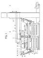
- the stacking device is used for stacking layers of crates 1 which are rectangular in plan with stacking corners 1 a running outwards for the position-safe reception of the crates inserted from above.
- the position consists of two longitudinal rows and three transverse rows of trays running at right angles to it.
- the stacking device is essentially composed of a base frame with a portal, in which a vertically movable lifting carriage 2 is guided.
- the lifting carriage 2 receives booms 3 which are movable in the horizontal direction on rollers with guideways in which a carriage 4 runs horizontally.
- An arrangement of holding elements 5 and 6 for the crates 1 is suspended on the carriage 4 and can be moved between a receiving point A and a delivery point B.
- the arrangement of holding elements consists of a row of individual folding surfaces 5, 6, which reach under the crates 1 in the area near the edge from two opposite sides and are pivoted jointly between a horizontal and vertical position for receiving or dispensing all crates of a layer.
- the folding surfaces 5, 6 end at the ends into diverging guide surfaces 5a, 6a, the inside dimension between the guide surfaces corresponding to the length of a tray, so that the trays are each surrounded by two interacting folding surfaces without play .
- the folding surfaces 5, 6 lying in series are arranged at a mutual distance from one another in such a way that a space for movement remains between adjacent guide surfaces 5a, 6a.
- actuating means for the folding surfaces and for the alignment elements described below are each provided on opposite sides, in the longitudinal as well as in the transverse direction. For reasons of simplicity, however, the following description essentially refers to the arrangement of the actuating means on only one side.
- the outer folding surfaces 5 are fastened to a common shaft 7, which is supported at the end in a pivot lever 12, which in turn is supported on a shaft 10 carried by side parts 11.
- the two side parts 11 are connected by a cross member 11a on which the carriage 4 is held.
- the inner folding surfaces 6 are each located on a shaft 16, 17, which are accommodated directly side by side by the side parts 11.
- the shafts 16, 17 have a small diameter, which consequently requires additional support.
- support bearings 18 are distributed on the cross member 11a between the sides at intervals over the wavelength share 11 provided.
- the folding surfaces 6 can also be arranged in a hinge-like manner on a common rotationally fixed shaft and pivoted about the rotationally fixed shaft via actuating means.
- the inner folding surfaces 6 receive their pivoting movement via a working cylinder 19, which is located on the side part 11 and actuates a U-shaped structural part 20 with its piston rod in the vertical plane, the arms of which are articulated on levers 21 on both sides.
- a further working cylinder 22 which is held in the side part 11, engages at a pivot point in the pivot lever 12 that is distant from the axis of rotation of the pivot lever 12. With the help of this working cylinder, the outer folding surfaces 5 carried by the pivot levers 12 can be pivoted by a defined distance to the center of the stacking device.
- crates 1 are pivoted towards the center of the stacking device by swiveling the vertical folding surfaces 5 located in the vertical position, and thus in the transverse direction via the cooperating divergent guide surfaces 5a, 6a of the respective folding surfaces 5, 6 see above as simultaneously aligned in the longitudinal direction via the folding surfaces 5, 6 themselves.
- the crates 1 assume the position shown in dash-dotted lines, bearing against the central support bearings 18.
- the stacking device is additionally provided with a device for pre-aligning with aligning elements 24, which act on opposite longitudinal sides on the respective previously deposited tray position before a subsequent layer of trays is released for stacking. This pre-alignment may be necessary if the trays are crooked due to a non-flat support surface.
- the alignment elements 24 have contact surfaces with angled, diverging guide surfaces 24a, the distance between the guide surfaces corresponding to the length of the riser layer.
- the movement of the alignment elements 24 mounted on the swivel levers 12 toward the center of the stacking device takes place via a working cylinder 25 which is arranged between the alignment element 24 and the shaft 10 with the interposition of a lever 26.
- the stacking device can also be provided with hold-down elements 27 which each extend over the row of trays and which can be lowered onto the trays 1 via working cylinders 28 with the task of pushing through the centering frames formed by the folding surfaces 5, 6 in the case of extremely light trays enable.
Landscapes
- Stacking Of Articles And Auxiliary Devices (AREA)
- Rigid Containers With Two Or More Constituent Elements (AREA)
- Pile Receivers (AREA)
Applications Claiming Priority (2)
| Application Number | Priority Date | Filing Date | Title |
|---|---|---|---|
| DE3837413A DE3837413A1 (de) | 1988-11-04 | 1988-11-04 | Vorrichtung zum ineinanderstapeln von steigen |
| DE3837413 | 1988-11-04 |
Publications (2)
| Publication Number | Publication Date |
|---|---|
| EP0366943A1 true EP0366943A1 (fr) | 1990-05-09 |
| EP0366943B1 EP0366943B1 (fr) | 1992-11-11 |
Family
ID=6366460
Family Applications (1)
| Application Number | Title | Priority Date | Filing Date |
|---|---|---|---|
| EP89118169A Expired - Lifetime EP0366943B1 (fr) | 1988-11-04 | 1989-09-30 | Dispositif pour emboîter de caisses à claire-voie |
Country Status (2)
| Country | Link |
|---|---|
| EP (1) | EP0366943B1 (fr) |
| DE (2) | DE3837413A1 (fr) |
Cited By (6)
| Publication number | Priority date | Publication date | Assignee | Title |
|---|---|---|---|---|
| US5263813A (en) * | 1989-12-11 | 1993-11-23 | Steinle Maschinenfabrik Gmbh | Apparatus having a gripping mechanism for the stacking and unstacking of containers |
| EP1285870A1 (fr) * | 2001-07-23 | 2003-02-26 | FPS Food Processing Systems B.V. | Dispositif de préhension |
| WO2009018895A1 (fr) * | 2007-08-06 | 2009-02-12 | Khs Ag | Procédé de désempilement ou d'empilement de fûts et dispositif pour la mise en oeuvre de ce procédé |
| ITUA20163512A1 (it) * | 2016-05-17 | 2017-11-17 | Co M A N S R L | Macchina e metodo per impilare cesti di contenimento di prodotti |
| CN114735482A (zh) * | 2022-03-31 | 2022-07-12 | 广东电网有限责任公司广州供电局 | 一种基于智能识别拆垛码设备 |
| WO2024160741A1 (fr) * | 2023-01-30 | 2024-08-08 | Autefa Solutions Germany Gmbh | Dispositif de manipulation de balles, procédé et entrepôt de balles |
Families Citing this family (3)
| Publication number | Priority date | Publication date | Assignee | Title |
|---|---|---|---|---|
| DE4033587A1 (de) * | 1990-10-22 | 1992-04-23 | Focke & Co | Vorrichtung zum handhaben von gegenstaenden, wie kartons |
| DE4338801A1 (de) * | 1993-11-13 | 1995-05-18 | Thomas A Ahbel | Verfahren und Vorrichtung zum Stapeln von Stückgütern |
| IT202100021458A1 (it) * | 2021-08-06 | 2023-02-06 | System Logistics S P A | Dispositivo di presa per cassette |
Citations (1)
| Publication number | Priority date | Publication date | Assignee | Title |
|---|---|---|---|---|
| US4592692A (en) * | 1984-02-23 | 1986-06-03 | Okura Yusoki Kabushiki Kaisha | Pallet loading apparatus |
Family Cites Families (6)
| Publication number | Priority date | Publication date | Assignee | Title |
|---|---|---|---|---|
| DE1201523B (de) * | 1962-03-28 | 1965-09-23 | Hans Lingl | Greifvorrichtung fuer Stapelgut, wie Baustoffe usw. |
| US3468436A (en) * | 1967-07-07 | 1969-09-23 | Sun Drop Bottling Co Inc | Machine for palletizing soft drink cases |
| DE6942953U (de) * | 1969-11-04 | 1970-04-23 | Wilhelm Becker & Co G M B H Fa | Vorrichtung zum waagerechten uebereinanderstapeln von betonplatten |
| GB1442301A (en) * | 1972-07-13 | 1976-07-14 | Redland Tiles Ltd | Clamps and vehicles therefor |
| DE2733985B2 (de) * | 1977-07-28 | 1980-04-03 | Enzinger-Union-Werke Ag, 6800 Mannheim | Vorrichtung zum schichtweisen Be- und Entladen von palettierten Behältern, insbesondere von Fässern |
| DD145257A1 (de) * | 1979-09-07 | 1980-12-03 | Harald Jesch | Greifer zum be-und entpalettieren von insbesondere flaschenkaestenlagen |
-
1988
- 1988-11-04 DE DE3837413A patent/DE3837413A1/de not_active Ceased
-
1989
- 1989-09-30 DE DE8989118169T patent/DE58902699D1/de not_active Expired - Fee Related
- 1989-09-30 EP EP89118169A patent/EP0366943B1/fr not_active Expired - Lifetime
Patent Citations (1)
| Publication number | Priority date | Publication date | Assignee | Title |
|---|---|---|---|---|
| US4592692A (en) * | 1984-02-23 | 1986-06-03 | Okura Yusoki Kabushiki Kaisha | Pallet loading apparatus |
Cited By (9)
| Publication number | Priority date | Publication date | Assignee | Title |
|---|---|---|---|---|
| US5263813A (en) * | 1989-12-11 | 1993-11-23 | Steinle Maschinenfabrik Gmbh | Apparatus having a gripping mechanism for the stacking and unstacking of containers |
| EP1285870A1 (fr) * | 2001-07-23 | 2003-02-26 | FPS Food Processing Systems B.V. | Dispositif de préhension |
| WO2009018895A1 (fr) * | 2007-08-06 | 2009-02-12 | Khs Ag | Procédé de désempilement ou d'empilement de fûts et dispositif pour la mise en oeuvre de ce procédé |
| US9302858B2 (en) | 2007-08-06 | 2016-04-05 | Khs Gmbh | Method for handling packages in a beverage bottling plant, a method for unstacking packages in a container filling plant, a method for stacking packages in a container filling plant, and arrangements for accomplishing the methods |
| ITUA20163512A1 (it) * | 2016-05-17 | 2017-11-17 | Co M A N S R L | Macchina e metodo per impilare cesti di contenimento di prodotti |
| WO2017199161A1 (fr) * | 2016-05-17 | 2017-11-23 | Co.M.A.N. S.R.L. | Machine et procédé permettant d'empiler des caisses permettant de contenir des produits |
| CN114735482A (zh) * | 2022-03-31 | 2022-07-12 | 广东电网有限责任公司广州供电局 | 一种基于智能识别拆垛码设备 |
| CN114735482B (zh) * | 2022-03-31 | 2023-10-20 | 广东电网有限责任公司广州供电局 | 一种基于智能识别拆垛码设备 |
| WO2024160741A1 (fr) * | 2023-01-30 | 2024-08-08 | Autefa Solutions Germany Gmbh | Dispositif de manipulation de balles, procédé et entrepôt de balles |
Also Published As
| Publication number | Publication date |
|---|---|
| EP0366943B1 (fr) | 1992-11-11 |
| DE58902699D1 (de) | 1992-12-17 |
| DE3837413A1 (de) | 1990-05-10 |
Similar Documents
| Publication | Publication Date | Title |
|---|---|---|
| DE3908496C2 (de) | Handhabungsvorrichtung für eine Biegemaschine, Verfahren zur Umkehrung der Lage eines Werkstückes in einem Biegeverfahren und Biegemaschine | |
| EP0541744B1 (fr) | Procede et dispositif d'empilement | |
| DE3520084C2 (de) | Rohrhandhabungssystem | |
| DE2846785B1 (de) | Vorrichtung zum automatischen Fuellen der Randfugen von Zwei- oder Mehrfach-Isolierglasscheiben mit einem Dichtungsmittel unter Verwendung von Fuellduesen | |
| DE3515729C2 (fr) | ||
| DE2512613C2 (de) | Sauggreifeinrichtung zum Erfassen und Handhaben eines quaderförmigen Körpers | |
| EP0366943B1 (fr) | Dispositif pour emboîter de caisses à claire-voie | |
| EP0436506A1 (fr) | Dispositif pour aligner des piles | |
| DE4024450A1 (de) | Geraet zum beschicken von verpackungsmaschinen mit stapeln aus geschichtetem material | |
| DE2852954C2 (de) | Verfahren zum Palettieren von offenen Behältern und Vorrichtung zu dessen Durchführung | |
| WO1998014288A1 (fr) | Machine a usiner | |
| CH618939A5 (fr) | ||
| DE2236188B2 (de) | Fördervorrichtung | |
| EP0489681B1 (fr) | Procédé et dispositif pour déplacer des pièces en forme de bandes ou de panneaux, empilés et juxtaposés sur une surface de support à faible coefficient de frottement | |
| DD159617A1 (de) | Vorrichtung zum aufnehmen und handhaben von flachen stapelfaehigen gegenstaenden | |
| DE2155455C3 (de) | Vorrichtung zum automatischen Abheben und Aufstapeln von Bohlen | |
| DE2559316A1 (de) | Verfahren und einrichtung zum abziehen einzelner platten oder von plattenpaketen von einem plattenstapel | |
| EP0075158B1 (fr) | Outil pour laver le parement de plaques en béton lavé nouvellement pressées | |
| DE29502308U1 (de) | Vorrichtung zum Transportieren von aus einem Blattpaketstapel entnehmbaren Blattpaketen | |
| DE9400777U1 (de) | Umsetzvorrichtung für Stapel aus parallelen Gegenständen | |
| DE2614009A1 (de) | Umsetzvorrichtung zum ergreifen von stueckguetern | |
| AT410660B (de) | Stapelgerät | |
| DE19814026A1 (de) | Vorrichtung zum Setzen von Magnetkörpern auf einer Schalungsplatte | |
| DE2939025C2 (de) | Nähvorrichtung | |
| CH447575A (de) | Maschine zum Abrichthobeln und Hobeln von Winkelkanten |
Legal Events
| Date | Code | Title | Description |
|---|---|---|---|
| PUAI | Public reference made under article 153(3) epc to a published international application that has entered the european phase |
Free format text: ORIGINAL CODE: 0009012 |
|
| AK | Designated contracting states |
Kind code of ref document: A1 Designated state(s): BE DE FR GB IT NL SE |
|
| RAP1 | Party data changed (applicant data changed or rights of an application transferred) |
Owner name: LEIFELD & LEMKE MASCHINENFABRIK GMBH & CO. KG |
|
| RAP1 | Party data changed (applicant data changed or rights of an application transferred) |
Owner name: LEIFELD & LEMKE MASCHINENFABRIK GMBH & CO. KG |
|
| 17P | Request for examination filed |
Effective date: 19901009 |
|
| 17Q | First examination report despatched |
Effective date: 19920430 |
|
| ITF | It: translation for a ep patent filed | ||
| GRAA | (expected) grant |
Free format text: ORIGINAL CODE: 0009210 |
|
| AK | Designated contracting states |
Kind code of ref document: B1 Designated state(s): BE DE FR GB IT NL SE |
|
| GBT | Gb: translation of ep patent filed (gb section 77(6)(a)/1977) | ||
| REF | Corresponds to: |
Ref document number: 58902699 Country of ref document: DE Date of ref document: 19921217 |
|
| ET | Fr: translation filed | ||
| PGFP | Annual fee paid to national office [announced via postgrant information from national office to epo] |
Ref country code: FR Payment date: 19930825 Year of fee payment: 6 |
|
| PLBE | No opposition filed within time limit |
Free format text: ORIGINAL CODE: 0009261 |
|
| STAA | Information on the status of an ep patent application or granted ep patent |
Free format text: STATUS: NO OPPOSITION FILED WITHIN TIME LIMIT |
|
| 26N | No opposition filed | ||
| REG | Reference to a national code |
Ref country code: FR Ref legal event code: ST |
|
| PGFP | Annual fee paid to national office [announced via postgrant information from national office to epo] |
Ref country code: SE Payment date: 19940826 Year of fee payment: 6 |
|
| PGFP | Annual fee paid to national office [announced via postgrant information from national office to epo] |
Ref country code: BE Payment date: 19940909 Year of fee payment: 6 |
|
| PGFP | Annual fee paid to national office [announced via postgrant information from national office to epo] |
Ref country code: GB Payment date: 19940929 Year of fee payment: 6 |
|
| PGFP | Annual fee paid to national office [announced via postgrant information from national office to epo] |
Ref country code: NL Payment date: 19940930 Year of fee payment: 6 |
|
| REG | Reference to a national code |
Ref country code: FR Ref legal event code: R1 |
|
| REG | Reference to a national code |
Ref country code: FR Ref legal event code: D1 |
|
| EAL | Se: european patent in force in sweden |
Ref document number: 89118169.5 |
|
| PG25 | Lapsed in a contracting state [announced via postgrant information from national office to epo] |
Ref country code: GB Effective date: 19950930 Ref country code: BE Effective date: 19950930 |
|
| PG25 | Lapsed in a contracting state [announced via postgrant information from national office to epo] |
Ref country code: SE Effective date: 19951001 |
|
| BERE | Be: lapsed |
Owner name: LEIFELD & LEMKE MASCHINENFABRIK G.M.B.H. & CO. K Effective date: 19950930 |
|
| PG25 | Lapsed in a contracting state [announced via postgrant information from national office to epo] |
Ref country code: NL Effective date: 19960401 |
|
| GBPC | Gb: european patent ceased through non-payment of renewal fee |
Effective date: 19950930 |
|
| PG25 | Lapsed in a contracting state [announced via postgrant information from national office to epo] |
Ref country code: FR Effective date: 19960531 |
|
| NLV4 | Nl: lapsed or anulled due to non-payment of the annual fee |
Effective date: 19960401 |
|
| EUG | Se: european patent has lapsed |
Ref document number: 89118169.5 |
|
| REG | Reference to a national code |
Ref country code: FR Ref legal event code: ST |
|
| PGFP | Annual fee paid to national office [announced via postgrant information from national office to epo] |
Ref country code: DE Payment date: 20021128 Year of fee payment: 14 |
|
| PG25 | Lapsed in a contracting state [announced via postgrant information from national office to epo] |
Ref country code: DE Free format text: LAPSE BECAUSE OF NON-PAYMENT OF DUE FEES Effective date: 20040401 |
|
| PG25 | Lapsed in a contracting state [announced via postgrant information from national office to epo] |
Ref country code: IT Free format text: LAPSE BECAUSE OF NON-PAYMENT OF DUE FEES Effective date: 20050930 |