EP0367041B1 - Überführungsvorrichtung für quaderförmige Gegenstände - Google Patents
Überführungsvorrichtung für quaderförmige Gegenstände Download PDFInfo
- Publication number
- EP0367041B1 EP0367041B1 EP89119482A EP89119482A EP0367041B1 EP 0367041 B1 EP0367041 B1 EP 0367041B1 EP 89119482 A EP89119482 A EP 89119482A EP 89119482 A EP89119482 A EP 89119482A EP 0367041 B1 EP0367041 B1 EP 0367041B1
- Authority
- EP
- European Patent Office
- Prior art keywords
- articles
- pusher
- driver
- drive
- Prior art date
- Legal status (The legal status is an assumption and is not a legal conclusion. Google has not performed a legal analysis and makes no representation as to the accuracy of the status listed.)
- Expired - Lifetime
Links
- 235000019504 cigarettes Nutrition 0.000 claims description 31
- 230000001360 synchronised effect Effects 0.000 claims description 4
- 238000012856 packing Methods 0.000 claims description 3
- 230000007423 decrease Effects 0.000 claims description 2
- 238000004806 packaging method and process Methods 0.000 description 5
- 230000001133 acceleration Effects 0.000 description 1
- 230000032823 cell division Effects 0.000 description 1
- 239000011888 foil Substances 0.000 description 1
Images

Classifications
-
- B—PERFORMING OPERATIONS; TRANSPORTING
- B65—CONVEYING; PACKING; STORING; HANDLING THIN OR FILAMENTARY MATERIAL
- B65B—MACHINES, APPARATUS OR DEVICES FOR, OR METHODS OF, PACKAGING ARTICLES OR MATERIALS; UNPACKING
- B65B19/00—Packaging rod-shaped or tubular articles susceptible to damage by abrasion or pressure, e.g. cigarettes, cigars, macaroni, spaghetti, drinking straws or welding electrodes
- B65B19/02—Packaging cigarettes
- B65B19/22—Wrapping the cigarettes; Packaging the cigarettes in containers formed by folding wrapping material around formers
Definitions
- the invention relates to a transfer device for rectangular objects, in particular objects to be wrapped in cling film, preferably cigarette packets, with a conveyor for the successive delivery of the objects and a device for taking the delivered objects up to a straight slide for pushing the objects to a subsequent packaging station, in particular one Foil wrapping device (see for example DE-A-2 642 474).
- the object of the invention is to provide a device of the type mentioned, which enables very short cycle times and nevertheless a gentle treatment of the objects.
- entrainment members are provided for the flying transfer of the objects to a pocket of the device for carrying the objects, the pocket being coupled to a drive in such a way that it runs through a closed path, with a portion of its circulation in the direction of extension of the slider and the sequence of movements of the pocket and the slider are synchronized such that the slider has only a low relative speed when entering the pocket during its orbital movement in the direction of extension of the slider.
- the cuboid objects are moved synchronously in the transport direction by the take-away device, which comprises the pocket, and the slide, and each is transferred on the fly, so that they never come to a standstill, so that very short cycle times are made possible.
- the bag also has the task of making the impact speed of the slider as small as possible and of keeping the object in motion, so that no unnecessary stops are required, but a continuous transfer takes place.
- the bag makes it possible to save time for the forward and backward movements necessary for the transfers from the conveyor or to the subsequent packaging station.
- the movement of the bag in the direction in front of the slide relieves the pressure of a driving element for transferring the object from the conveyor into the pocket, so that there is practically no relative movement between the object and the driving element associated with friction.
- the latter After transferring the objects into the pocket, the latter is preferably moved into a position adjacent to a slide via a parallelogram drive and the object moved through the pocket in the direction of movement of the slide is conveyed further by the slide, the relative speed between the moment the slide hits the object can be brought to a low value, ie almost to zero, so that the articles are treated extremely gently.
- the actual speed of the object and the pusher at the moment of impact is the speed of the bag in relation to the machine frame of the packaging machine. After the slider strikes the object, the slider is correspondingly accelerated to push the object out of the pocket into a subsequent receiving member.
- the object can be inserted into the bag using a drive wheel.
- cigarette packets 1 to be provided with a cover made of transparent film are fed via a conveyor, not shown.
- the cigarette packs 1 are conveyed one against the other with a narrow side downwards and pressed in the direction of the driving wheel 3, so that after taking a cigarette pack 1 with a driving nose 4, the following cigarette pack 1 comes into contact with the driving wheel 3.
- the diameter of the driving wheel 3 between two driving lugs 4 decreases continuously by the radial length of the driving lug 4, so that the pack of cigarettes 1 coming into contact continuously comes into the recess in front of the respective driving lug 4.
- the driving wheel 3 pushes the respectively received cigarette packet 1 into a pocket 6.
- the pocket 6 is connected to a parallelogram drive 7, which comprises two rods 8, which are each connected to one side of the pocket 6.
- the rods 8 are hinged at the other end to a crank 9 which is seated on a shaft 10.
- a link 11 is articulated on each rod 8, the other end of which is rotatably mounted about a fixed axis 11a.
- the crank 9 and the link 11 have the same length, the longitudinal axes of the rods 8 always running parallel to the connecting line of the center points of the shaft 10 and the axes 11a.
- the pocket 6 is moved by the parallelogram drive 7 in a movement consisting of a vertical and a horizontal component out of the path of the driving wheel 3 in the conveying direction up to a slide guide 13 so that the carried cigarette packet 1 comes to rest against a resilient upper stop 12.
- the driving wheel 3 by continuing to turn the driving wheel 3, the cigarette packet 1 is pushed further and further into the pocket 6 until it is completely accommodated in the pocket 6 and the corresponding driving nose 4 dips away.
- the slide guide 13 receives a slide 14 which is displaceable via a crank 15 in order to push the cigarette packet 1 upon alignment of the pocket 6 with the slide guide 13 and a feed channel through the latter into a cell of a revolver, not shown, during the passage of the feed channel, a corresponding section made of transparent film, which is held ready to extend across the conveyor path of the slide 14, is taken along.
- the movements of pocket 6 and slider 14 are coordinated such that the slider 14 has a speed almost equal to that of the cigarette packet 1 when it hits the cigarette packet 1 moved from the bag 6 in the direction of the feed channel, which speed then increases to the cigarette packet 1 slide out of pocket 6. In this way, the cigarette packets 1 are handled extremely gently despite the high packaging speeds.
- the pocket 6 has bottom-side slot-shaped recesses 6 '(Fig. 2) through which the driver lugs 4 dive away when transferring the cigarette packet 1, while the pocket 6 on the top side only has edge strips 6', so that the slide 14 is unhindered by the movement of the pocket 6 drive through and emerge from the pocket 6.
- the cigarette packet 1 Due to the "flying transfers", the cigarette packet 1 remains completely in the flow and does not suffer a standstill which impairs the conveying speed.
- the drive takes place via a common drive shaft 17, with which a gear wheel 18 connected to the shaft 2 is in meshing engagement. Furthermore, there are two cam disks 19, 20 arranged at a distance from one another on the drive shaft 17, while the shaft 10 is connected to a lever 21 which carries two rollers 22 which engage with the cam disks 19 and 20, via which the crank 9 passes - And pivoted here and thus the pocket 6 is moved synchronized with the movement of the driving wheel 3.
- the revolver in the cells of which the cigarette packs 1 are inserted for wrapping in the section made of transparent film, is also driven by the drive shaft 17 via corresponding gear elements step by step in accordance with the cell division of the revolver in synchronization with the shaft 2.
- the driving wheel 3 can, as can be seen from Fig. 2, have a circumferential radial groove 24, so that the driving wheel 3 consists essentially of two axially spaced and connected via a hub part wheel parts.
- the side parts of the pocket 6 each have a longitudinally extending groove 25 on the outside, while the rods 8 have corresponding projections 26 which are received by the grooves 25, so that changing the pocket 6 does not require any complex adjustment.
- the conveyor for delivering the cigarette packs 1 comprises a belt 28 provided with driving lugs 4 and guided around corresponding deflection wheels 27, the Drive lugs 4 push the cigarette packs 1 into the pocket 6 one after the other.
- the pocket-side deflection wheel 27 can also be designed like the driving wheel 3 and can be provided with driving lugs 4 instead of the belt 28.
- a multi-joint drive can also be used.
Landscapes
- Engineering & Computer Science (AREA)
- Mechanical Engineering (AREA)
- Wrapping Of Specific Fragile Articles (AREA)
Description
- Die Erfindung betrifft eine Überführungsvorrichtung für quaderförmige Gegenstände, insbesondere in Klarsichtfolie einzuhüllende Gegenstände, vorzugsweise Zigarettenpäckchen, mit einem Förderer zum aufeinanderfolgenden Anliefern der Gegenstände und einer Einrichtung zum Mitnehmen der angelieferten Gegenstände bis vor einen geradgeführten Schieber zum Überschieben der Gegenstände zu einer nachfolgenden Verpackungsstation, insbesondere eine Folieneinschlageinrichtung (siche zum Beispiel DE-A- 2 642 474).
- Beim Verpacken von Zigaretten ist es bekannt, diese zunächst mit einem Innen- und einem Außenpapier zu versehen, so daß entsprechende Zigarettenpäckchen erhalten werden, die anschließend noch mit Klarsichtfolie umhüllt werden. Hierzu werden die Zigarettenpäckchen über einen Förderer der entsprechenden verpackungsstation einer Folienschlagmaschine im wesentlichen horizontal zugeführt, vertikal auf die Höhe eines Zuführkanals angehoben und mittels eines Schiebers unter Mitnahme eines entsprechenden Folienabschnitts in eine Zelle eines Umhüllungsrevolvers eingeführt. Da jedoch immer höhere Taktzeiten angestrebt werden, werden die relativ empfindlichen Zigarettenpäckchen bei einer derartigen Überführung immer größeren Beanspruchungen unterworfen, denen sie häufig nicht mehr standhalten können.
- Zwar ist es an sich bekannt, einem Schieber zum Kerschieben von Zigarettenpäckchen durch eine Kurvensteuerung einen Bewegungsablauf zu verleihen, der dazu führt, daß der Schieber mit einer Geschwindigkeit nahezu gleich null auf das Zigarettenpäckchen auftrifft, um dann beschleunigt zu werden, so daß die Zigarettenpäckchen geschont werden. Jedoch nimmt das Abbremsen bis nahezu zum Stillstand und das anschließend notwendige Beschleunigen relativ viel Zeit in Anspruch.
- Aufgabe der Erfindung ist es, eine Vorrichtung der eingangs genannten Art zu schaffen, die sehr kurze Taktzeiten und trotzdem eine schonende Behandlung der Gegenstände ermöglicht.
- Diese Aufgabe wird dadurch gelöst, daß Mitnahmeorgane zum fliegenden Übergeben der Gegenstände an eine Tasche der Einrichtung zum Mitnehmen der Gegenstände vorgesehen ist, wobei die Tasche mit einem Antrieb derart gekoppelt ist, daß sie einen geschlossenen Weg durchläuft, wobei sich ein Abschnitt ihres Umlaufs in Ausschubrichtung des Schiebers erstreckt und der Bewegungsablauf der Tasche und des Schiebers derart synchronisiert sind, daß der Schieber zur Tasche beim Eintreten in die Tasche während deren Umlaufbewegung in Ausschubrichtung des Schiebers nur eine geringe Relativgeschwindigkeit aufweist.
- Die quaderförmigen Gegenstände werden durch die Einrichtung zum Mitnehmen, die die Tasche umfaßt, und den Schieber in Transportrichtung synchronisiert bewegt und jeweils fliegend übergeben, so daß sie nirgends im Stillstand kommen, so daß sehr kurze Taktzeiten ermöglicht werden. Hierbei hat die Tasche zudem die Aufgabe, die Aufprallgeschwindigkeit des Schiebers möglichst klein zu machen und den Gegenstand in Bewegung zu halten, so daß keine unnötigen Stops benötigt werden, sondern eine kontinuierliche Übergabe erfolgt. Die Tasche erlaubt es, die Zeit für die bei den Überführungen vom Förderer bzw. zu der nachfolgenden Verpackungsstation notwendigen Vor- und Rückbewegungen zu gewinnen. Wenn die Tasche den Gegenstand aufgenommen hat, wird zugleich durch die Bewegung der Tasche in Richtung vor den Schieber der Druck eines Mitnahmeorgans zum Überführen des Gegenstandes vom Förderer in die Tasche entlastet, so daß praktisch keine mit Reibung verbundene Relativbewegung zwischen Gegenstand und Mitnehmerorgan auftritt.
- Nach Überführen der Gegenstände in die Tasche wird letztere vorzugsweise über einen Parallelogrammantrieb in eine Position benachbart zu einem Schieber bewegt und der durch die Tasche in Bewegungsrichtung des Schiebers bewegte Gegenstand vom Schieber weiterbefördert, wobei im Moment des Auftreffens des Schiebers auf den Gegenstand die Relativgeschwindigkeit hierzwischen auf einen geringen Wert, d.h. nahezu auf null, gebracht werden kann, so daß sich eine äußerst schonende Behandlung der Gegenstände ergibt.
- Die tatsächliche Geschwindigkeit des Gegenstandes und des Schiebers im Moment des Auftreffens ist aber die Geschwindigkeit der Tasche gegenüber dem Maschinenrahmen der Verpackungsmaschine. Nach dem Auftreffen des Schiebers auf den Gegenstand wird der Schieber zum Ausschieben des Gegenstandes aus der Tasche in ein nachfolgendes Aufnahmeorgan entsprechend beschleunigt. Das Einführen des Gegenstandes in die Tasche kann über ein Mitnehmerrad erfolgen.
- Weitere Ausgestaltungen der Erfindung sind der nachfolgenden Beschreibung und den Unteransprüchen zu entnehmen.
- Die Erfindung wird nachstehend anhand eines in den beigefügten Abbildungen dargestellten Ausführungsbespiels näher erläutert.
- Fig. 1 zeigt vereinfacht in Frontansicht eine Überführungsvorrichtung für Zigarettenpäckchen von einem Förderer zu einem Folieneinschlagrevolver.
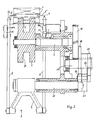
- Fig. 2 zeigt die Vorrichtung von Fig. 1 teilweise geschnitten in Blickrichtung von rechts nach links bezüglich Fig. 1.
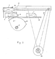
- Fig. 3 zeigt eine weitere Ausführungsform vereinfacht in Frontansicht.
- Bei der dargestellten Vorrichtung werden mit einer Hülle aus Klarsichtfolie zu versehende Zigarettenpäckchen 1 über einen nicht dargestellten Förderer zugeführt. Ein auf einer Welle 2 montiertes Mitnehmerrad 3, das im dargestellten Ausführungsbeispiel mit drei gleichmäßig über den Umfang verteilten Mitnehmernasen 4 versehen ist, nimmt über jeweils eine Mitnehmernase 4 ein Zigarettenpäckchen 1 um etwa 90° mit, wobei das Zigarettenpäckchen 1 nach außen hin durch ein kreisausschnittförmiges Führungsblech 5 abgestützt wird.
- Die Zigarettenpäckchen 1 werden aneinanderliegend mit einer Schmalseite nach unten angefördert und in Richtung auf das Mitnehmerrad 3 gedrückt, so daß nach Mitnahme eines Zigarettenpäckchens 1 durch eine Mitnehmernase 4 das nachfolgende Zigarettenpäckchen 1 in Anlage an das Mitnehmerrad 3 gelangt. In Drehrichtung nimmt der Durchmesser des Mitnehmerrades 3 jeweils zwischen zwei Mitnehmernasen 4 kontinuierlich um die radiale Länge der Mitnehmernase 4 ab, so daß das zur Anlage kommende Zigarettenpäckchen 1 kontinuierlich in die Ausnehmung vor der jeweiligen Mitnehmernase 4 gelangt.
- Das Mitnehmerrad 3 schiebt das jeweils übernommene Zigarettenpäckchen 1 in eine Tasche 6. Die Tasche 6 ist mit einem Parallelogrammantrieb 7 verbunden, der zwei Stangen 8 umfaßt, die jeweils mit einer Seite der Tasche 6 verbunden sind. Die Stangen 8 sind mit dem anderen Ende an einer Kurbel 9 angelenkt, die auf einer Welle 10 sitzt. Ferner ist an jeder Stange 8 ein Lenker 11 angelenkt, der mit dem anderen Ende um eine ortsfeste Achse 11a drehbar gelagert ist. Die Kurbel 9 und die Lenker 11 haben gleiche Länge, wobei die Längsachsen der Stangen 8 zu der Verbindungslinie der Mittelpunkte der Welle 10 und der Achsen 11a immer parallel verlaufen.
- Bereits wenn die Tasche 6 das Zigarettenpäckchen 1 teilweise aufgenommen hat, wird die Tasche 6 durch den Parallelogrammantrieb 7 in einer entsprechend aus einer vertikalen und einer horizontalen Komponente bestehenden Bewegung aus der Bahn des Mitnehmerrades 3 heraus in Förderrichtung bis vor eine Schieberführung 13 bewegt, so daß das mitgeführte Zigarettenpäckchen 1 gegen einen federnden oberen Anschlag 12 zur Anlage gelangt. Zu Beginn dieser Bewegung wird durch das Weiterdrehen des Mitnehmerrades 3 das Zigarettenpäckchen 1 fortschreitend weiter in die Tasche 6 eingeschoben, bis es ganz von der Tasche 6 aufgenommen ist und die entsprechende Mitnehmernase 4 wegtaucht.
- Die Schieberführung 13 nimmt einen Schieber 14 auf, der über eine Kurbel 15 verschiebbar ist, um das Zigarettenpäckchen 1 bei Ausrichtung der Tasche 6 mit der Schieberführung 13 und einem Zuführkanal durch den letzteren hindurch in eine Zelle eines nicht dargestellten Revolvers zu schieben, wobei beim Durchlaufen des Zuführkanals ein entsprechender ,Abschnitt aus Klarsichtfolie, der sich quer über die Förderbahn des Schiebers 14 erstreckend bereit gehalten wird, mitgenommen wird. Dabei sind die Bewegungen von Tasche 6 und Schieber 14 derart koordiniert, daß der Schieber 14 beim Auftreffen auf das von der Tasche 6 in Richtung des Zuführkanals bewegte Zigarettenpäckchen 1 eine Geschwindigkeit nahezu gleich derjenigen des Zigarettenpäckchens 1 hat, die sich dann erhöht, um das Zigarettenpäckchen 1 aus der Tasche 6 auszuschieben. Auf diese Weise ergibt sich eine äußerst schonende Handhabung der Zigarettenpäckchen 1 trotz hoher Verpackungsgeschwindigkeiten.
- Die Tasche 6 besitzt bodenseitig schlitzförmige Ausnehmungen 6′ (Fig. 2), durch die die Mitnehmernasen 4 bei der Übergabe des Zigarettenpäckchens 1 wegtauchen, während die Tasche 6 oberseitig nur Randleisten 6˝ aufweist, so daß der Schieber 14 ungehindert von der Bewegung der Tasche 6 hindurchfahren und aus der Tasche 6 austreten kann.
- Das Zigarettenpäckchen 1 bleibt aufgrund der "fliegenden Übergaben" vollständig im Fluß und erleidet keinen die Fördergeschwindigkeit beeinträchtigenden Stillstand.
- Der Antrieb erfolgt über eine gemeinsame Antriebswelle 17, mit der ein mit der Welle 2 verbundenes Zahnrad 18 in kämmendem Eingriff steht. Ferner befinden sich auf der Antriebswelle 17 zwei mit Abstand zueinander angeordnete Kurvenscheiben 19, 20, während die Welle 10 mit einem Hebel 21 verbunden ist, der zwei mit den Kurvenscheiben 19 bzw. 20 in Eingriff stehende Rollen 22 trägt, über die die Kurbel 9 hin- und hergeschwenkt und damit die Tasche 6 synchronisiert mit der Bewegung des Mitnehmerrades 3 bewegt wird.
- Entsprechende Kurvenscheiben auf der Antriebswelle 17 und ein mit der Welle 23 der Kurbel 15 verbundener Hebel dienen zum Bewegen des Schiebers 14 in Synchronisation mit dem Mitnehmerrad 3 und der Tasche 6.
- Der Revolver, in dessen Zellen die Zigarettenpäckchen 1 zum Einhüllen in den Abschnitt aus Klarsichtfolie eingeschoben werden, wird ebenfalls durch die Antriebswelle 17 über entsprechende Getriebeelemente schrittweise entsprechend der Zellenteilung des Revolvers in Synchronisation zur Welle 2 angetrieben.
- Das Mitnehmerrad 3 kann, wie aus Fig. 2 ersichtlich ist, eine umlaufende Radialnut 24 aufweisen, so daß das Mitnehmerrad 3 im wesentlichen aus zwei mit axialem Abstand zueinander angeordneten und über ein Nabenteil verbundenen Radteilen besteht.
- Die Seitenteile der Tasche 6 besitzen außenseitig jeweils eine sich in Längsrichtung erstreckende Nut 25, während die Stangen 8 entsprechende Vorsprünge 26 aufweisen, die von den Nuten 25 aufgenommen werden, so daß ein Auswechseln der Tasche 6 keine aufwendige Justierung nötig macht.
- Bei der in Fig. 3 dargestellten Ausführungsform umfaßt der Förderer zum Anliefern der Zigarettenpäckchen 1 einen mit Mitnehmernasen 4 versehenen, um entsprechende Umlenkräder 27 geführten Gurt 28, wobei die Mitnehmernasen 4 die Zigarettenpäckchen 1 aufeinanderfolgend in die Tasche 6 einschieben. Hierbei kann auch das taschenseitige Umlenkrad 27 wie das Mitnehmerrad 3 ausgebildet und anstelle des Gurtes 28 mit Mitnehmernasen 4 versehen sein.
- Anstelle eines Parallelogrammantriebs 7 kann auch ein Mehrgelenkantrieb verwendet werden.
Claims (11)
Applications Claiming Priority (2)
| Application Number | Priority Date | Filing Date | Title |
|---|---|---|---|
| DE3836874A DE3836874A1 (de) | 1988-10-29 | 1988-10-29 | Ueberfuehrungsvorrichtung fuer quaderfoermige gegenstaende |
| DE3836874 | 1988-10-29 |
Publications (2)
| Publication Number | Publication Date |
|---|---|
| EP0367041A1 EP0367041A1 (de) | 1990-05-09 |
| EP0367041B1 true EP0367041B1 (de) | 1992-06-03 |
Family
ID=6366144
Family Applications (1)
| Application Number | Title | Priority Date | Filing Date |
|---|---|---|---|
| EP89119482A Expired - Lifetime EP0367041B1 (de) | 1988-10-29 | 1989-10-20 | Überführungsvorrichtung für quaderförmige Gegenstände |
Country Status (2)
| Country | Link |
|---|---|
| EP (1) | EP0367041B1 (de) |
| DE (2) | DE3836874A1 (de) |
Families Citing this family (1)
| Publication number | Priority date | Publication date | Assignee | Title |
|---|---|---|---|---|
| CN114789820B (zh) * | 2021-01-26 | 2024-06-18 | 登封市启明轩程控设备有限公司 | 一种纸包挂面装袋机 |
Family Cites Families (10)
| Publication number | Priority date | Publication date | Assignee | Title |
|---|---|---|---|---|
| DE863617C (de) * | 1949-04-29 | 1953-01-19 | Rose Brothers Ltd | Verpackungsmaschine zum Umhuellen von Zigarettenpackungen od. dgl. |
| DE1274951B (de) * | 1964-10-21 | 1968-08-08 | Alfred Schmermund | Maschine zum Einhuellen blockfoermiger Gegenstaende |
| GB1083602A (en) * | 1965-01-30 | 1967-09-20 | Skoda Np | Improved device for turning and aligning prismatic boxes |
| US3789576A (en) * | 1972-06-05 | 1974-02-05 | Buren Ind Inc Van | Wrapping apparatus with rotary horizontal lift |
| CH570322A5 (de) * | 1974-01-18 | 1975-12-15 | Sapal Plieuses Automatiques | |
| IT1049141B (it) * | 1975-09-24 | 1981-01-20 | Amf Sasib Spa | Dispositivo impilatore trasferitore per macchine cellofanatrici di pacchetti.in particolare pacchetti di sigarette |
| US4096953A (en) * | 1977-03-21 | 1978-06-27 | Cincinnati Milacron Inc. | Mechanism to transfer workpieces between locations |
| NL7810420A (nl) * | 1977-12-29 | 1979-07-03 | Sig Schweiz Industrieges | Sorteerinrichting in de transportbaan van langwerpige voorwerpen. |
| US4549645A (en) * | 1982-11-11 | 1985-10-29 | Molins Plc | Feeding articles |
| DE3328323A1 (de) * | 1983-08-05 | 1985-02-21 | Maschinenfabrik Alfred Schmermund Gmbh & Co, 5820 Gevelsberg | Vorrichtung zum ausschieben stabfoermiger gegenstaende |
-
1988
- 1988-10-29 DE DE3836874A patent/DE3836874A1/de not_active Ceased
-
1989
- 1989-10-20 EP EP89119482A patent/EP0367041B1/de not_active Expired - Lifetime
- 1989-10-20 DE DE8989119482T patent/DE58901602D1/de not_active Expired - Fee Related
Also Published As
| Publication number | Publication date |
|---|---|
| EP0367041A1 (de) | 1990-05-09 |
| DE58901602D1 (de) | 1992-07-09 |
| DE3836874A1 (de) | 1990-05-03 |
Similar Documents
| Publication | Publication Date | Title |
|---|---|---|
| EP0034377B2 (de) | Verfahren und Vorrichtung zum Einführen von Gegenständen, insbesondere Packungen, in die Umlaufbahn eines kontinuierlichen Förderers | |
| DE3545884C2 (de) | Vorrichtung zum Herstellen von (Zigaretten-) Packungen aus mindestens einem faltbaren Zuschnitt | |
| DE3046065C2 (de) | Bodenfaltungspacker | |
| EP0275481B2 (de) | Verfahren und Vorrichtung zum Verpacken von Papier-Taschentüchern | |
| DE2425969C2 (de) | ||
| EP0197368A2 (de) | Verfahren und Vorrichtung zum Verpacken von insbesondere Zigaretten | |
| DE3824316A1 (de) | Verfahren und vorrichtung zum herstellen einer quaderfoermigen packung | |
| EP0304736B1 (de) | Verfahren und Vorrichtung zum Einhüllen von insbesondere Zigaretten-Packungen | |
| DE4040261A1 (de) | Vorrichtung zum anbringen von streifen an im wesentlichen parallelflachen paeckchen | |
| DE3619714A1 (de) | Zufuhrvorrichtung fuer steuerbanderolen in einer zigaretten-verpackungsmaschine | |
| DE69802165T2 (de) | Verfahren und vorrichtung zum anbringen von lösbaren etiketten auf annähernd quaderförmigen verpackungen | |
| DE2711471A1 (de) | Vorrichtung zum einstellen und ausscheiden von verpackungsmaterialabschnitten (aus staniolpapier) in hochleistungs- zigarettenverpackungsmaschinen | |
| EP0143961B1 (de) | Vorrichtung zum Einhüllen von Gegenständen, insbesondere Zigaretten-Gruppen | |
| EP0418687B1 (de) | Bodenfaltungspacker | |
| DE3939558C2 (de) | Verfahren zum Verpacken von Zigaretten | |
| DE60310904T2 (de) | Einwickelmaschine | |
| DE2032184A1 (de) | Vorrichtung zum Herstellen und Füllen von Weichpackungen | |
| DE4202308A1 (de) | Kaugummi-verpackungsmaschine | |
| EP0367041B1 (de) | Überführungsvorrichtung für quaderförmige Gegenstände | |
| DE2211736A1 (de) | Verfahren und Vorrichtung zum Übertragen insbesondere von Etiketten aus einer Vorratseinrichtung auf eine Arbeitsstraße | |
| DE2329534C3 (de) | Vorrichtung zum kontinuierlichen Einwickeln von Bonbons oder ähnlichen Kleinteilen | |
| DE602004011729T2 (de) | Verpackungsvorrichtung | |
| EP0133664B1 (de) | Vorrichtung zum Ausschieben stabförmiger Gegenstände | |
| DE4001587C1 (en) | Feed magazine for cigarette packing machine - gathers cigarettes in pockets on conveyor belt | |
| DE3705941C1 (en) | Method and apparatus for the direct transfer to a packaging machine of cigarettes coming from a manufacturing machine |
Legal Events
| Date | Code | Title | Description |
|---|---|---|---|
| PUAI | Public reference made under article 153(3) epc to a published international application that has entered the european phase |
Free format text: ORIGINAL CODE: 0009012 |
|
| AK | Designated contracting states |
Kind code of ref document: A1 Designated state(s): DE FR GB IT |
|
| 17P | Request for examination filed |
Effective date: 19900519 |
|
| 17Q | First examination report despatched |
Effective date: 19910613 |
|
| GRAA | (expected) grant |
Free format text: ORIGINAL CODE: 0009210 |
|
| AK | Designated contracting states |
Kind code of ref document: B1 Designated state(s): DE FR GB IT |
|
| GBT | Gb: translation of ep patent filed (gb section 77(6)(a)/1977) | ||
| REF | Corresponds to: |
Ref document number: 58901602 Country of ref document: DE Date of ref document: 19920709 |
|
| ET | Fr: translation filed | ||
| ITF | It: translation for a ep patent filed | ||
| PLBE | No opposition filed within time limit |
Free format text: ORIGINAL CODE: 0009261 |
|
| STAA | Information on the status of an ep patent application or granted ep patent |
Free format text: STATUS: NO OPPOSITION FILED WITHIN TIME LIMIT |
|
| 26N | No opposition filed | ||
| PGFP | Annual fee paid to national office [announced via postgrant information from national office to epo] |
Ref country code: FR Payment date: 19961022 Year of fee payment: 8 |
|
| PG25 | Lapsed in a contracting state [announced via postgrant information from national office to epo] |
Ref country code: FR Free format text: THE PATENT HAS BEEN ANNULLED BY A DECISION OF A NATIONAL AUTHORITY Effective date: 19971031 |
|
| REG | Reference to a national code |
Ref country code: FR Ref legal event code: ST |
|
| REG | Reference to a national code |
Ref country code: GB Ref legal event code: IF02 |
|
| PGFP | Annual fee paid to national office [announced via postgrant information from national office to epo] |
Ref country code: GB Payment date: 20041011 Year of fee payment: 16 |
|
| PGFP | Annual fee paid to national office [announced via postgrant information from national office to epo] |
Ref country code: DE Payment date: 20050323 Year of fee payment: 16 |
|
| PG25 | Lapsed in a contracting state [announced via postgrant information from national office to epo] |
Ref country code: IT Free format text: LAPSE BECAUSE OF NON-PAYMENT OF DUE FEES Effective date: 20051020 Ref country code: GB Free format text: LAPSE BECAUSE OF NON-PAYMENT OF DUE FEES Effective date: 20051020 |
|
| PG25 | Lapsed in a contracting state [announced via postgrant information from national office to epo] |
Ref country code: DE Free format text: LAPSE BECAUSE OF NON-PAYMENT OF DUE FEES Effective date: 20060503 |
|
| GBPC | Gb: european patent ceased through non-payment of renewal fee |
Effective date: 20051020 |