EP0367065A1 - Abgas-Katalysator für Kraftfahrzeuge - Google Patents
Abgas-Katalysator für Kraftfahrzeuge Download PDFInfo
- Publication number
- EP0367065A1 EP0367065A1 EP89119660A EP89119660A EP0367065A1 EP 0367065 A1 EP0367065 A1 EP 0367065A1 EP 89119660 A EP89119660 A EP 89119660A EP 89119660 A EP89119660 A EP 89119660A EP 0367065 A1 EP0367065 A1 EP 0367065A1
- Authority
- EP
- European Patent Office
- Prior art keywords
- housing
- exhaust gas
- monolith
- catalytic converter
- gas catalytic
- Prior art date
- Legal status (The legal status is an assumption and is not a legal conclusion. Google has not performed a legal analysis and makes no representation as to the accuracy of the status listed.)
- Withdrawn
Links
Images

Classifications
-
- F—MECHANICAL ENGINEERING; LIGHTING; HEATING; WEAPONS; BLASTING
- F01—MACHINES OR ENGINES IN GENERAL; ENGINE PLANTS IN GENERAL; STEAM ENGINES
- F01N—GAS-FLOW SILENCERS OR EXHAUST APPARATUS FOR MACHINES OR ENGINES IN GENERAL; GAS-FLOW SILENCERS OR EXHAUST APPARATUS FOR INTERNAL-COMBUSTION ENGINES
- F01N13/00—Exhaust or silencing apparatus characterised by constructional features
- F01N13/14—Exhaust or silencing apparatus characterised by constructional features having thermal insulation
-
- F—MECHANICAL ENGINEERING; LIGHTING; HEATING; WEAPONS; BLASTING
- F01—MACHINES OR ENGINES IN GENERAL; ENGINE PLANTS IN GENERAL; STEAM ENGINES
- F01N—GAS-FLOW SILENCERS OR EXHAUST APPARATUS FOR MACHINES OR ENGINES IN GENERAL; GAS-FLOW SILENCERS OR EXHAUST APPARATUS FOR INTERNAL-COMBUSTION ENGINES
- F01N3/00—Exhaust or silencing apparatus having means for purifying, rendering innocuous, or otherwise treating exhaust
- F01N3/08—Exhaust or silencing apparatus having means for purifying, rendering innocuous, or otherwise treating exhaust for rendering innocuous
- F01N3/10—Exhaust or silencing apparatus having means for purifying, rendering innocuous, or otherwise treating exhaust for rendering innocuous by thermal or catalytic conversion of noxious components of exhaust
- F01N3/24—Exhaust or silencing apparatus having means for purifying, rendering innocuous, or otherwise treating exhaust for rendering innocuous by thermal or catalytic conversion of noxious components of exhaust characterised by constructional aspects of converting apparatus
- F01N3/28—Construction of catalytic reactors
- F01N3/2839—Arrangements for mounting catalyst support in housing, e.g. with means for compensating thermal expansion or vibration
- F01N3/2853—Arrangements for mounting catalyst support in housing, e.g. with means for compensating thermal expansion or vibration using mats or gaskets between catalyst body and housing
- F01N3/2857—Arrangements for mounting catalyst support in housing, e.g. with means for compensating thermal expansion or vibration using mats or gaskets between catalyst body and housing the mats or gaskets being at least partially made of intumescent material, e.g. unexpanded vermiculite
-
- F—MECHANICAL ENGINEERING; LIGHTING; HEATING; WEAPONS; BLASTING
- F01—MACHINES OR ENGINES IN GENERAL; ENGINE PLANTS IN GENERAL; STEAM ENGINES
- F01N—GAS-FLOW SILENCERS OR EXHAUST APPARATUS FOR MACHINES OR ENGINES IN GENERAL; GAS-FLOW SILENCERS OR EXHAUST APPARATUS FOR INTERNAL-COMBUSTION ENGINES
- F01N3/00—Exhaust or silencing apparatus having means for purifying, rendering innocuous, or otherwise treating exhaust
- F01N3/08—Exhaust or silencing apparatus having means for purifying, rendering innocuous, or otherwise treating exhaust for rendering innocuous
- F01N3/10—Exhaust or silencing apparatus having means for purifying, rendering innocuous, or otherwise treating exhaust for rendering innocuous by thermal or catalytic conversion of noxious components of exhaust
- F01N3/24—Exhaust or silencing apparatus having means for purifying, rendering innocuous, or otherwise treating exhaust for rendering innocuous by thermal or catalytic conversion of noxious components of exhaust characterised by constructional aspects of converting apparatus
- F01N3/28—Construction of catalytic reactors
- F01N3/2839—Arrangements for mounting catalyst support in housing, e.g. with means for compensating thermal expansion or vibration
- F01N3/2875—Arrangements for mounting catalyst support in housing, e.g. with means for compensating thermal expansion or vibration by using elastic means, e.g. spring leaves, for retaining catalyst body in the housing
-
- F—MECHANICAL ENGINEERING; LIGHTING; HEATING; WEAPONS; BLASTING
- F01—MACHINES OR ENGINES IN GENERAL; ENGINE PLANTS IN GENERAL; STEAM ENGINES
- F01N—GAS-FLOW SILENCERS OR EXHAUST APPARATUS FOR MACHINES OR ENGINES IN GENERAL; GAS-FLOW SILENCERS OR EXHAUST APPARATUS FOR INTERNAL-COMBUSTION ENGINES
- F01N2330/00—Structure of catalyst support or particle filter
- F01N2330/02—Metallic plates or honeycombs, e.g. superposed or rolled-up corrugated or otherwise deformed sheet metal
-
- F—MECHANICAL ENGINEERING; LIGHTING; HEATING; WEAPONS; BLASTING
- F01—MACHINES OR ENGINES IN GENERAL; ENGINE PLANTS IN GENERAL; STEAM ENGINES
- F01N—GAS-FLOW SILENCERS OR EXHAUST APPARATUS FOR MACHINES OR ENGINES IN GENERAL; GAS-FLOW SILENCERS OR EXHAUST APPARATUS FOR INTERNAL-COMBUSTION ENGINES
- F01N2330/00—Structure of catalyst support or particle filter
- F01N2330/06—Ceramic, e.g. monoliths
-
- Y—GENERAL TAGGING OF NEW TECHNOLOGICAL DEVELOPMENTS; GENERAL TAGGING OF CROSS-SECTIONAL TECHNOLOGIES SPANNING OVER SEVERAL SECTIONS OF THE IPC; TECHNICAL SUBJECTS COVERED BY FORMER USPC CROSS-REFERENCE ART COLLECTIONS [XRACs] AND DIGESTS
- Y02—TECHNOLOGIES OR APPLICATIONS FOR MITIGATION OR ADAPTATION AGAINST CLIMATE CHANGE
- Y02A—TECHNOLOGIES FOR ADAPTATION TO CLIMATE CHANGE
- Y02A50/00—TECHNOLOGIES FOR ADAPTATION TO CLIMATE CHANGE in human health protection, e.g. against extreme weather
- Y02A50/20—Air quality improvement or preservation, e.g. vehicle emission control or emission reduction by using catalytic converters
Definitions
- the invention relates to the storage of a catalytically coated monolith in the housing of an exhaust gas catalytic converter for fuel-operated engines according to the preamble of claim 1 and a method for producing such an exhaust gas catalytic converter.
- Exhaust gas catalysts for fuel-operated engines usually consist of a catalytically coated monolith, preferably a honeycomb ceramic body or metal body, which is mounted safely and gas-tight in a sheet steel housing with the aid of suitable elements. From the very beginning, the attention of the inventors and designers was focused on these sealing and bearing elements. These elements have to meet extreme requirements. They have to compensate for the thermal expansion differences between the monolith and the housing elastically, withstand the high exhaust gas and catalytic converter temperatures above 800 degrees C and withstand the pressure pulsations of the exhaust gas.
- DE-B-22 20 921 discloses a construction in which the housing inner shell is held and sealed both with respect to the housing outer shell and with respect to the monolith by means of wire mesh and / or swelling mats.
- DE-B-23 10 207 discloses a construction with a film-like inner wall, wherein the space between the inner wall and the outer wall is pressurized to hold the monolith.
- DE-A-37 00 070 discloses a construction in which inner shells are provided in the region of the transition cones of the housing, the space between the inner shell and the housing being filled with insulating material.
- the monolith is stored in the housing in a conventional manner using so-called swelling mats.
- the wire mesh and swelling mats are first wound onto the monoliths and, in the alternative, fixed with auxiliary devices - adhesive strips, wires and the like. This applies in the same way to any additional components that may be provided.
- This package is then placed in the sheet metal housing, which usually consists of two half-shells, this is closed with the aid of a suitable device, care being taken to ensure that the sealing and bearing elements and other built-in parts are not jammed, and finally welded in a gastight manner. It is not possible to correct the housing position of the monolith, the bearing elements and / or the other built-in parts. This also applies when using double-walled housings.
- the present invention is based on the object of specifying an exhaust gas catalytic converter of the type mentioned at the outset and a method for its production in which the assembly effort is considerably reduced and the monolith position can be checked and corrected.
- the sealing elements required in the production of the exhaust gas catalytic converter according to the invention only have to have relatively small dimensions and low strength values. Since the actual gas-tight and temperature-resistant seal is only introduced after the housing has been closed, low forces are sufficient to close the housing, which consists of two half-shells. Instead of hydraulic presses, simple mechanical toggle lever devices can now be used during assembly. In addition, the correct position of the monolith can be checked and corrected if necessary.
- the sealing elements first have the task of reliably limiting the spread of the filled filling compound until it hardens. In later operation, they protect the ends of the filling compound; they must therefore also be resistant to high temperatures and pressure pulsations.
- the housing preferably has a closable opening for introducing the filling compound into the intermediate space.
- the opening is closed by suitable procedures.
- the housing also has at least one opening for venting the intermediate space during filling. This allows a simple filler neck without its own ventilation opening to be used to fill or press in the filling compound.
- the sealing elements are designed as sealing rings, which consist of a wire mesh covered with filling material.
- These sealing rings made of temperature-resistant material serve, among other things, to mitigate the effects of pressure pulsations on the filling compound during operation.
- the sealing elements are designed as sheet metal cones, which are led into the housing connecting piece.
- the transition between sheet metal cones and monolith is initially sealed with an adhesive sealing strip during assembly.
- the sealing elements are designed as corrugated tubes which are sealed against the housing connecting piece or the housing cones.
- This modification also provides for increased thermal insulation of the housing, but is associated with a higher elasticity of the monolith bearing in the axial direction.
- the pasty filling compound must be set accordingly in order to be able to fill all areas of the space between the housing, monolith and sealing elements. It can therefore be advisable to activate the filling compound after filling or pressing in and closing the housing openings.
- This activation means the solidification such.
- a monolith 1 can be seen as the catalytically active element, usually in the form of a ceramic body or metal body with honeycomb-shaped channels which are coated with noble metal.
- the monolith 1 is located in a sheet steel housing 2 with any cross section.
- Connection pieces 2.2 are provided for connection to the exhaust gas pipes not shown in the drawing. Adjacent to the connection piece 2.2, the housing has 2 connection cones 2.1.
- a gap 5 is formed between the monolith 1 and the housing 2. This is filled or pressed with a pasty filling compound, with sealing rings 3, for example made of knitted fabrics or mats of metal and / or ceramic threads, optionally coated with filling compound, axially limiting the spreading of the sealing compound.
- sealing rings 3 for example made of knitted fabrics or mats of metal and / or ceramic threads, optionally coated with filling compound, axially limiting the spreading of the sealing compound.
- a filling opening 4 is provided in the housing 2, onto which a filler neck 3 can be placed.
- at least one vent opening 6 is optionally provided.
- the primary task of the sealing rings 3 is to correct the monolith 1 before introducing the filling compound To keep housing 2 and limit the axial spread of the filling compound.
- the correct position of the monolith 1 in the housing 2 can be checked at any time and corrected if necessary through the openings 4, 6 and through the connecting cones 2.2.
- the final fixation and storage takes place by introducing and activating the filling compound.
- FIG. 2 A second embodiment is shown in FIG. 2.
- the monolith 1 is positioned in the housing 2 with the aid of inner cones 8 which extend into the connecting pieces 2.2.
- the housing 2 is protected against heat loss in the area of the cones 2.1 after the introduction of the filling compound, which has a heat-insulating effect due to its composition, without a special operation being necessary.
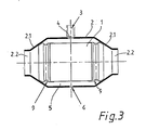
- FIG. 3 A third embodiment is shown in FIG. 3.
- the monolith 1 is mounted in a modification to the embodiment in accordance with FIG. 2 by corrugated tubes 9 which are fastened on the inside to the housing cones 2.1. If further thermal insulation of the housing 2 is desired, the corrugated pipes 9 can also be extended into the housing connecting piece 2.2.
Landscapes
- Chemical & Material Sciences (AREA)
- Engineering & Computer Science (AREA)
- Chemical Kinetics & Catalysis (AREA)
- Combustion & Propulsion (AREA)
- Mechanical Engineering (AREA)
- General Engineering & Computer Science (AREA)
- Health & Medical Sciences (AREA)
- Toxicology (AREA)
- Exhaust Gas After Treatment (AREA)
Abstract
Die Erfindung betrifft einen Abgas-Katalysator für kraftstoffbetriebene Motoren. Der katalytisch beschichtete Monolith (1) ist in einem Stahlblechgehäuse (2) gelagert. Der Zwischenraum zwischen Monolith (1) und Gehäuse (2) ist stirnseitig durch Dichtelemente in Form von Wellrohren (9) begrenzt. Der Zwischenraum (5) ist mit einer pastösen Füllmasse verfüllt, die durch eine verschließbare Öffnung (4) eingebracht wird und nach ihrer Aktivierung den Monolithen (1) im Gehäuse (2) fixiert und gegebenenfalls thermisch isoliert.
Description
- Die Erfindung betrifft die Lagerung eines katalytisch beschichteten Monolithen im Gehäuse eines Abgas-Katalysators für kraftstoffbetriebene Motoren gemäß dem Oberbegriff des Anspruchs 1 sowie ein Verfahren zur Herstellung eines solchen Abgas-Katalysators.
- Abgas-Katalysatoren für kraftstoffbetriebene Motoren bestehen üblicherweise aus einem katalytisch beschichteten Monolithen, vorzugsweise einem Waben-Keramikkörper oder Metallkörper, der mit Hilfe von geeigneten Elementen sicher und gasdicht in einem Stahlblechgehäuse gelagert ist. Auf diese Dicht- und Lagerelemente hat sich von Anfang an die Aufmerksamkeit der Erfinder und Konstrukteure gerichtet. Diese Elemente müssen extremen Anforderungen genügen. Sie müssen die thermischen Ausdehnungsunterschiede zwischen Monolith und Gehäuse elastisch ausgleichen, die hohen Abgas- und Katalysetemperaturen über 800 Grad C aushalten und dabei den Druckpulsationen des Abgases standhalten.
- Als Dichtelemente und Lagerungselemente bewährt haben sich sogenannte Gestricke aus Metall- und/oder Keramikfäden sowie Quellmatten. An der Innenseite des Blechgehäuses angeschweißte Ringflansche, die ursprünglich zum Schutz der Lagerungselemente eingesetzt wurden, konnten sich nicht durchsetzen.
- Es ist auch schon mehrfach vorgeschlagen worden, die Gehäuse doppelwandig auszubilden. Die DE-B-22 20 921 offenbart eine Konstruktion, bei der die Gehäuse-Innenschale sowohl gegenüber der Gehäuse-Außenschale als auch gegenüber dem Monolithen mit Hilfe von Drahtgestricken und/oder Quellmatten gehalten und abgedichtet ist.
- Die DE-B-23 10 207 offenbart eine Konstruktion mit einer folienartigen Innenwand, wobei der Zwischenraum zwischen Innenwand und Außenwand mit Druckgas beaufschlagt wird, um den Monolithen zu halten.
- Die DE-A-37 00 070 offenbart eine Konstruktion, bei der Innenschalen im Bereich der Übergangskonen des Gehäuses vorgesehen sind, wobei der Zwischenraum zwischen Innenschale und Gehäuse mit Isoliermaterial gefüllt wird. Die Lagerung des Monolithen im Gehäuse erfolgt in konventioneller Weise mittels sogenannter Quellmatten.
- Bei der Montage werden die Drahtgestricke und Quellmatten zunächst auf den Monolithen aufgewickelt und mit Hilfsvorrichtungen - Klebestreifen, Drähte und dergleichen - hilfsweise fixiert. Dies gilt in gleicher Weise für gegebenenfalls vorgesehene zusätzliche Einbauteile. Dieses Paket wird dann in das üblicherweise aus zwei Halbschalen bestehende Blechgehäuse gelegt, dieses wird mit Hilfe einer geeigneten Vorrichtung geschlossen, wobei darauf geachtet werden muß, daß die Dicht- und Lagerelemente und sonstigen Einbauteile nicht verklemmt werden, und abschließend gasdicht verschweißt. Eine Korrektur der Gehäuseposition des Monolithen, der Lagerungselemente und/oder der sonstigen Einbauteile ist nicht möglich. Dies gilt auch bei Verwendung doppelwandiger Gehäuse.
- Der vorliegenden Erfindung liegt die Aufgabe zugrunde, einen Abgas-Katalysator der eingangs genannten Art sowie ein Verfahren zu seiner Herstellung anzugeben, bei dem der Montageaufwand erheblich verringert und eine Kontrolle und Korrektur der Monolithenposition möglich ist.
- Diese Aufgabe wird gelöst durch einen Abgas-Katalysator der gattungsgemäßen Art mit den kennzeichnenden Merkmalen des Anspruchs 1, vorzugsweise in Verbindung mit einem Herstellungsverfahren mit den kennzeichnenden Merkmalen des Anspruchs 9.
- Damit ergeben sich die Vorteile, daß die bei der Herstellung des erfindungsgemäßen Abgas-Katalysators benötigten Dichtelemente nur noch relativ kleine Abmessungen und geringe Festigkeitswerte haben müssen. Da die eigentliche gasdichte und temperaturfeste Abdichtung erst nach dem Schließen des Gehäuses eingebracht wird, genügen geringe Kräfte, um das aus zwei Halbschalen bestehende Gehäuse zu schließen. Anstelle von hydraulischen Pressen können bei der Montage jetzt einfache mechanische Kniehebelvorrichtungen eingesetzt werden. Außerdem kann die korrekte Position des Monolithen kontrolliert und gegebenenfalls korrigiert werden. Die Dichtelemente haben zunächst die Aufgabe, die Ausbreitung der eingefüllten Füllmasse bis zu deren Erhärten sicher zu begrenzen. Im späteren Betrieb schützen sie die Enden der Füllmasse; sie müssen deshalb auch hochtemperaturfest und druckpulsationsfest sein.
- Vorzugsweise weist das Gehäuse eine verschließbare Öffnung zum Einbringen der Füllmasse in den Zwischenraum auf. Das Verschließen der Öffnung wird durch geeignete Verfahren sichergestellt.
- Zusätzlich weist das Gehäuse auch wenigstens eine Öffnung zum Entlüften des Zwischenraums während des Befüllens auf. Dies erlaubt es, zum Einfüllen bzw. Einpressen der Füllmasse einen einfachen Füllstutzen ohne eigene Entlüftungsöffnung zu verwenden.
- Für die Ausgestaltung der Dichtelemente, die den Zwischenraum zwischen Monolith und Gehäuse in axialer Richtung begrenzen, sind mehrere alternative Ausführungsformen möglich.
- Gemäß einer ersten Alternative sind die Dichtelemente als Dichtringe ausgebildet, die aus einem füllmassendicht ummantelten Drahtgestrick bestehen. Diese Dichtringe aus temperaturbeständigem Material dienen unter anderem dazu, während des Betriebs die Einwirkungen der Druckpulsationen auf die Füllmasse zu mildern.
- Gemäß einer zweiten Alternative sind die Dichtelemente als Blechkonen ausgebildet, die bis in die Gehäusestutzen geführt sind. Der Übergang zwischen Blechkonen und Monolith wird bei der Montage zunächst durch einen Klebedichtstreifen abgedichtet. Bei dieser konstruktiven Ausführung entsteht eine Art Doppelmantel im Gehäuse, der in einem Arbeitsgang mit Füllmasse verfüllt bzw. verpreßt wird, wodurch auch eine in vielen Fällen erwünschte Wärmeisolierung des Gehäuses erreicht wird.
- Gemäß einer dritten Alternative sind die Dichtelemente als Wellrohre ausgebildet, die gegen die Gehäusestutzen oder die Gehäusekonen abgedichtet sind. Auch bei dieser Abwandlung ist eine erweiterte Wärmeisolierung des Gehäuses gegeben, verbunden jedoch mit einer höheren Elastizität der Monolithenlagerung in axialer Richtung.
- Die pastöse Füllmasse muß entsprechend eingestellt sein, um alle Bereiche des Zwischenraums zwischen Gehäuse, Monolith und Dichtelementen ausfüllen zu können. Deshalb kann es sich empfehlen, die Füllmasse nach dem Einfüllen bzw. Einpressen und dem Verschließen der Gehäuseöffnungen zu aktivieren.
- Dieses Aktivieren bedeutet das Verfestigen wie z. B. Quellen, der Füllmasse, ausgelöst durch physikalische und/oder chemische Prozesse oder vergleichbare Vorgänge.
- Anhand der Zeichnung soll die Erfindung in Form von Ausführungsbeispielen näher erläutert werden. Es zeigen jeweils im Längsschnitt und in schematischer Darstellung
- Fig. 1 eine erste Ausführungsform eines Abgas-Katalysators,
- Fig. 2 eine zweite Ausführungsform eines Abgas-Katalysators,
- Fig. 3 eine dritte Ausführungsform eines Abgas-Katalysators.
- In allen Figuren erkennt man als katalytisch wirksames Element einen Monolithen 1, meist in Form eines Keramikkörpers oder Metallkörpers mit wabenförmigen Kanälen, die mit Edelmetall beschichtet sind. Der Monolith 1 befindet sich in einem Stahlblechgehäuse 2 mit beliebigem Querschnitt. Zur Verbindung mit den in der Zeichnung nicht dargestellten abgasführenden Rohren sind Anschlußstutzen 2.2 vorgesehen. Benachbart zu den Anschlußstutzen 2.2 besitzt das Gehäuse 2 Anschlußkonen 2.1.
- Zwischen Monolith 1 und Gehäuse 2 ist ein Zwischenraum 5 ausgebildet. Dieser wird mit einer pastösen Füllmasse verfüllt bzw. verpreßt, wobei Dichtringe 3, beispielsweise aus Gestricken oder Matten von Metall- und/oder Keramikfäden, gegebenenfalls füllmassendicht ummantelt, die Ausbreitung der Dichtmasse axial begrenzen. Zum Einfüllen der Füllmasse ist im Gehäuse 2 eine Einfüllöffnung 4 vorgesehen, auf die ein Einfüllstutzen 3 aufgesetzt werden kann. Um den Zwischenraum 5 beim Einfüllen der Füllmasse entlüften zu können, ist gegebenenfalls wenigstens eine Entlüftungsöffnung 6 vorgesehen.
- Die primäre Aufgabe der Dichtringe 3 besteht darin, den Monolithen 1 vor dem Einbringen der Füllmasse korrekt im Gehäuse 2 zu halten und die axiale Ausbreitung der Füllmasse zu begrenzen. Durch die Öffnungen 4, 6 sowie durch die Anschlußkonen 2.2 kann die korrekte Lage des Monolithen 1 im Gehäuse 2 jederzeit überprüft und nötigenfalls korrigiert werden. Die endgültige Fixierung und Lagerung erfolgt durch Einbringen und Aktivieren der Füllmasse.
- Eine zweite Ausführungsform zeigt die Fig. 2. Hier wird der Monolith 1 mit Hilfe von Innenkonen 8, die bis in die Anschlußstutzen 2.2 hineinreichen, im Gehäuse 2 positioniert. Zusätzlich ist das Gehäuse 2 nach dem Einbringen der Füllmasse, die aufgrund ihrer Zusammensetzung wärmeisolierend wirkt, auch im Bereich der Konen 2.1 gegen Wärmeverluste geschützt, ohne daß ein besonderer Arbeitsvorgang erforderlich wäre.
- Eine dritte Ausführungsform zeigt Fig. 3. Hier erfolgt die Lagerung des Monolithen 1 in Abwandlung zur Ausführungsform gemäß Fig. 2 durch Wellrohre 9, die innen an den Gehäusekonen 2.1 befestigt sind. Falls eine weitergehende Wärmeisolierung des Gehäuses 2 angestrebt wird, können die Wellrohre 9 auch bis in die Gehäusestutzen 2.2 verlängert werden.
Claims (10)
1. Abgas-Katalysator für kraftstoffbetriebene Motoren, bestehend aus einem katalytisch beschichteten Monolithen (1), einem Blechgehäuse (2) und Elementen (7, 8, 9, 10) zur sicheren und gasdichten Lagerung des Monolithen (1) im Gehäuse (2), dadurch gekennzeichnet, daß der zwischen Monolith (1) und Gehäuse (2) gebildete Zwischenraum (5) durch die Elemente (7, 8, 9, 10) stirnseitig abgedichtet und mit einer pastösen Füllmasse verfüllt bzw. verpreßt ist.
2. Abgas-Katalysator nach Anspruch 1, dadurch gekennzeichnet, daß die eingebrachte Füllmasse zur Lagerung des Monolithen im Stahlgehäuse dient.
3. Abgas-Katalysator nach Anspruch 1, dadurch gekennzeichnet, daß die eingebrachte Füllmasse zusätzlich zur thermischen Isolation dient.
4. Abgas-Katalysator nach Anspruch 1, 2 oder 3, dadurch gekennzeichnet, daß das Gehäuse (2) eine verschließbare Öffnung (4) zum Einbringen der Dichtmasse in den Zwischenraum (5) aufweist.
5. Abgas-Katalysator nach wenigstens einem der Ansprüche 1 bis 4, dadurch gekennzeichnet, daß das Gehäuse (2) wenigstens eine Öffnung (6) zum Entlüften des Zwischenraums (5) aufweist.
6. Abgas-Katalysator nach wenigstens einem der Ansprüche 1 bis 5, dadurch gekennzeichnet, daß die Dichtelemente als Dichtinge (7) ausgebildet sind, die im Neuzustand füllmassendicht ummantelt sind.
7. Abgas-Katalysator nach wenigstens einem der Ansprüche 1 bis 5, dadurch gekennzeichnet, daß die Dichtelemente als Blechkonen (8) ausgebildet sind, die bis in die Gehäusestutzen (2.2) geführt und dort abgedichtet sind.
8. Abgas-Katalysator nach wenigstens einem der Ansprüche 1 bis 5, dadurch gekennzeichnet, daß die Dichtelemente als Wellrohre (9) ausgebildet sind, die gegen die Gehäusestutzen (2.2) oder die Gehäusekonen (2.1) gedichtet sind.
9. Verfahren zur Herstellung einer sicheren und gasdichten Lagerung eines katalytisch beschichteten Monolithen (1) in einem Blechgehäuse (2), wobei zwischen Monolith (1) und Gehäuse (2) Dichtelemente (7, 8, 9, 10) eingebracht sind, zur Herstellung eines Abgas-Katalysators nach den Ansprüchen 1 bis 8, dadurch gekennzeichnet, daß nach dem Einsetzen des Monolithen (1) in das Gehäuse (2) und dem Schließen desselben der Zwischenraum (5) zwischen Gehäuse (2), Monolith (1) und Dichtelementen (7, 8, 9, 10) mit einer Füllmasse verfüllt bzw. verpreßt wird.
10. Verfahren nach Anspruch 9, dadurch gekennzeichnet, daß die Füllmasse nach dem Einfüllen bzw. Einpressen und dem Verschließen der Gehäuseöffnungen (4, 6) aktiviert wird.
Applications Claiming Priority (2)
| Application Number | Priority Date | Filing Date | Title |
|---|---|---|---|
| DE3837503 | 1988-11-04 | ||
| DE3837503A DE3837503A1 (de) | 1988-11-04 | 1988-11-04 | Abgas-katalysator fuer kraftfahrzeuge |
Publications (1)
| Publication Number | Publication Date |
|---|---|
| EP0367065A1 true EP0367065A1 (de) | 1990-05-09 |
Family
ID=6366518
Family Applications (1)
| Application Number | Title | Priority Date | Filing Date |
|---|---|---|---|
| EP89119660A Withdrawn EP0367065A1 (de) | 1988-11-04 | 1989-10-24 | Abgas-Katalysator für Kraftfahrzeuge |
Country Status (2)
| Country | Link |
|---|---|
| EP (1) | EP0367065A1 (de) |
| DE (2) | DE3837503A1 (de) |
Cited By (5)
| Publication number | Priority date | Publication date | Assignee | Title |
|---|---|---|---|---|
| EP0492418A1 (de) * | 1990-12-24 | 1992-07-01 | Emitec Gesellschaft für Emissionstechnologie mbH | Vorrichtung zur katalytischen Entgiftung von Abgasen, vorzugsweise Abgasen von Verbrennungskraftmaschinen |
| WO1996027735A1 (de) * | 1995-03-08 | 1996-09-12 | Emitec Gesellschaft Für Emissionstechnologie Mbh | Metallischer wabenkörper |
| WO1999064731A1 (de) * | 1998-06-05 | 1999-12-16 | Emitec Gesellschaft Für Emissionstechnologie Mbh | Wabenkörperanordnung |
| US6509769B2 (en) | 1999-12-10 | 2003-01-21 | Siemens Aktiengesellschaft | Clock signal generator/converter device |
| CN116289802A (zh) * | 2023-02-22 | 2023-06-23 | 南京威铁网络科技有限公司 | 一种用于水利工程的闸门拉杆起吊机构及其应用方法 |
Families Citing this family (1)
| Publication number | Priority date | Publication date | Assignee | Title |
|---|---|---|---|---|
| DE10035194C2 (de) * | 2000-07-20 | 2003-02-27 | Arvin Exhaust Gmbh | Katalysatorbauteil |
Citations (7)
| Publication number | Priority date | Publication date | Assignee | Title |
|---|---|---|---|---|
| DE2300704A1 (de) * | 1973-01-08 | 1974-07-11 | Eberspaecher J | Anordnung zur katalytischen reinigung der abgase von brennkraftmaschinen |
| FR2211041A5 (de) * | 1972-12-16 | 1974-07-12 | Eberspaecher J | |
| DE2341265A1 (de) * | 1973-08-16 | 1975-03-06 | Volkswagenwerk Ag | Einrichtung zur katalytischen abgasreinigung |
| US3938232A (en) * | 1973-04-28 | 1976-02-17 | Toyota Jidosha Kogyo Kabushiki Kaisha | Method of manufacturing catalyst type exhaust gas purifier |
| DE2627596A1 (de) * | 1976-06-19 | 1978-02-02 | Zeuna Staerker Kg | Vorrichtung zur katalytischen reinigung der abgase an brennkraftmaschinen |
| FR2467975A1 (fr) * | 1979-10-22 | 1981-04-30 | Uop Inc | Convertisseur catalytique de gaz d'echappement et procede de reduction des fuites de derivation |
| EP0210103A1 (de) * | 1985-07-16 | 1987-01-28 | Ecia - Equipements Et Composants Pour L'industrie Automobile | Auspuffanlage für Kraftfahrzeuge und dergleichen |
Family Cites Families (2)
| Publication number | Priority date | Publication date | Assignee | Title |
|---|---|---|---|---|
| DE2220921C2 (de) * | 1972-04-28 | 1974-05-30 | Zeuna-Staerker Kg, 8900 Augsburg | Vorrichtung zur katalytischen reinigung der auspuffgase von brennkraftmaschinen |
| DE3700070A1 (de) * | 1987-01-02 | 1988-07-14 | Eberspaecher J | Vorrichtung fuer die katalytische reinigung von fahrzeugmotor-abgasen |
-
1988
- 1988-11-04 DE DE3837503A patent/DE3837503A1/de not_active Ceased
- 1988-11-04 DE DE8817016U patent/DE8817016U1/de not_active Expired - Lifetime
-
1989
- 1989-10-24 EP EP89119660A patent/EP0367065A1/de not_active Withdrawn
Patent Citations (7)
| Publication number | Priority date | Publication date | Assignee | Title |
|---|---|---|---|---|
| FR2211041A5 (de) * | 1972-12-16 | 1974-07-12 | Eberspaecher J | |
| DE2300704A1 (de) * | 1973-01-08 | 1974-07-11 | Eberspaecher J | Anordnung zur katalytischen reinigung der abgase von brennkraftmaschinen |
| US3938232A (en) * | 1973-04-28 | 1976-02-17 | Toyota Jidosha Kogyo Kabushiki Kaisha | Method of manufacturing catalyst type exhaust gas purifier |
| DE2341265A1 (de) * | 1973-08-16 | 1975-03-06 | Volkswagenwerk Ag | Einrichtung zur katalytischen abgasreinigung |
| DE2627596A1 (de) * | 1976-06-19 | 1978-02-02 | Zeuna Staerker Kg | Vorrichtung zur katalytischen reinigung der abgase an brennkraftmaschinen |
| FR2467975A1 (fr) * | 1979-10-22 | 1981-04-30 | Uop Inc | Convertisseur catalytique de gaz d'echappement et procede de reduction des fuites de derivation |
| EP0210103A1 (de) * | 1985-07-16 | 1987-01-28 | Ecia - Equipements Et Composants Pour L'industrie Automobile | Auspuffanlage für Kraftfahrzeuge und dergleichen |
Non-Patent Citations (1)
| Title |
|---|
| PATENT ABSTRACTS OF JAPAN vol. 8, no. 189 (M-321)(1626) 30 August 1984, & JP-A-59 079025 (MAZDA) 08 Mai 1984 * |
Cited By (5)
| Publication number | Priority date | Publication date | Assignee | Title |
|---|---|---|---|---|
| EP0492418A1 (de) * | 1990-12-24 | 1992-07-01 | Emitec Gesellschaft für Emissionstechnologie mbH | Vorrichtung zur katalytischen Entgiftung von Abgasen, vorzugsweise Abgasen von Verbrennungskraftmaschinen |
| WO1996027735A1 (de) * | 1995-03-08 | 1996-09-12 | Emitec Gesellschaft Für Emissionstechnologie Mbh | Metallischer wabenkörper |
| WO1999064731A1 (de) * | 1998-06-05 | 1999-12-16 | Emitec Gesellschaft Für Emissionstechnologie Mbh | Wabenkörperanordnung |
| US6509769B2 (en) | 1999-12-10 | 2003-01-21 | Siemens Aktiengesellschaft | Clock signal generator/converter device |
| CN116289802A (zh) * | 2023-02-22 | 2023-06-23 | 南京威铁网络科技有限公司 | 一种用于水利工程的闸门拉杆起吊机构及其应用方法 |
Also Published As
| Publication number | Publication date |
|---|---|
| DE8817016U1 (de) | 1991-12-19 |
| DE3837503A1 (de) | 1990-05-10 |
Similar Documents
| Publication | Publication Date | Title |
|---|---|---|
| DE2629462C2 (de) | ||
| EP1047865B1 (de) | Wabenkörperanordnung mit einer mindestens eine metallfolie enthaltenden zwischenschicht | |
| DE69414792T3 (de) | Keramische wabenförmige Katalysatoreinrichtung | |
| DE2823549C3 (de) | Vorrichtung zur katalytischen Gasbehandlung | |
| DE2401455A1 (de) | Behaelter fuer katalysatoren zur steuerung und kontrolle der abgasemission bei brennkraftmaschinen und verfahren zu deren fertigung | |
| EP0582985A1 (de) | Abgaskrümmer | |
| DE2213540A1 (de) | Katalysatorkoerper zur reinigung der abgase von brennkraftmaschinen | |
| DE19780763B3 (de) | Gasgenerator für einen Airbag | |
| WO2001011209A1 (de) | Abgaskrümmer | |
| DE3878495T2 (de) | Verfahren zum schuetzen und isolieren eines katalysator-blocks. | |
| WO1981000738A1 (fr) | Dispositif pour l'epuration catalytique des gaz d'echappement d'un moteur a combustion | |
| EP0674944B1 (de) | Verfahren zur Herstellung eines beschichteten, monolithischen Metallträgers | |
| EP2852738B2 (de) | Abgasnachbehandlungseinrichtung und zugehöriges herstellungsverfahren | |
| EP0367065A1 (de) | Abgas-Katalysator für Kraftfahrzeuge | |
| DE19523532A1 (de) | Katalysatoranordnung mit zwei- oder mehrsträngiger Abgasführung | |
| DE4306052A1 (en) | Catalytic exhaust cleaning system for vehicle - uses soldered joints to connect honeycombed core to outer housing | |
| EP0306705B1 (de) | Trägerkörper für die Herstellung eines katalytischen Reaktors zur Abgasreinigung | |
| EP1399655B1 (de) | Mantelförmiges mittelteil eines katalysatorgehäuses | |
| DE3100939A1 (de) | Katalytische reinigungseinheit fuer abgase von verbrennungsmotoren und verfahren zu ihrer herstellung | |
| WO1999024700A1 (de) | Katalysator-trägerkörper mit freiliegenden wärmeabstrahlungsflächen | |
| EP1859132B1 (de) | Gehäuse für eine abgasbehandlungskomponente mit verstärkungshülse | |
| EP1241331B1 (de) | Katalysator-Trichter und Katalysatorgehäuse | |
| DE7401002U (de) | Behälter für Katalysator zur Steuerung und Kontrolle der Abgasemission bei Brennkraftmaschinen | |
| DE102005023168B4 (de) | Abgasreinigungsvorrichtung | |
| DE4427459A1 (de) | Abgasanlage |
Legal Events
| Date | Code | Title | Description |
|---|---|---|---|
| PUAI | Public reference made under article 153(3) epc to a published international application that has entered the european phase |
Free format text: ORIGINAL CODE: 0009012 |
|
| AK | Designated contracting states |
Kind code of ref document: A1 Designated state(s): DE ES FR GB IT SE |
|
| 17P | Request for examination filed |
Effective date: 19900329 |
|
| 17Q | First examination report despatched |
Effective date: 19910403 |
|
| STAA | Information on the status of an ep patent application or granted ep patent |
Free format text: STATUS: THE APPLICATION HAS BEEN WITHDRAWN |
|
| 18W | Application withdrawn |
Withdrawal date: 19910930 |