EP0367072A1 - Disjoncteur à haute tension à gaz diélectrique sous pression - Google Patents
Disjoncteur à haute tension à gaz diélectrique sous pression Download PDFInfo
- Publication number
- EP0367072A1 EP0367072A1 EP89119712A EP89119712A EP0367072A1 EP 0367072 A1 EP0367072 A1 EP 0367072A1 EP 89119712 A EP89119712 A EP 89119712A EP 89119712 A EP89119712 A EP 89119712A EP 0367072 A1 EP0367072 A1 EP 0367072A1
- Authority
- EP
- European Patent Office
- Prior art keywords
- contact
- tube
- circuit breaker
- cylinder
- piston
- Prior art date
- Legal status (The legal status is an assumption and is not a legal conclusion. Google has not performed a legal analysis and makes no representation as to the accuracy of the status listed.)
- Granted
Links
Images

Classifications
-
- H—ELECTRICITY
- H01—ELECTRIC ELEMENTS
- H01H—ELECTRIC SWITCHES; RELAYS; SELECTORS; EMERGENCY PROTECTIVE DEVICES
- H01H33/00—High-tension or heavy-current switches with arc-extinguishing or arc-preventing means
- H01H33/70—Switches with separate means for directing, obtaining, or increasing flow of arc-extinguishing fluid
- H01H33/88—Switches with separate means for directing, obtaining, or increasing flow of arc-extinguishing fluid the flow of arc-extinguishing fluid being produced or increased by movement of pistons or other pressure-producing parts
- H01H33/90—Switches with separate means for directing, obtaining, or increasing flow of arc-extinguishing fluid the flow of arc-extinguishing fluid being produced or increased by movement of pistons or other pressure-producing parts this movement being effected by or in conjunction with the contact-operating mechanism
- H01H33/901—Switches with separate means for directing, obtaining, or increasing flow of arc-extinguishing fluid the flow of arc-extinguishing fluid being produced or increased by movement of pistons or other pressure-producing parts this movement being effected by or in conjunction with the contact-operating mechanism making use of the energy of the arc or an auxiliary arc
- H01H33/903—Switches with separate means for directing, obtaining, or increasing flow of arc-extinguishing fluid the flow of arc-extinguishing fluid being produced or increased by movement of pistons or other pressure-producing parts this movement being effected by or in conjunction with the contact-operating mechanism making use of the energy of the arc or an auxiliary arc and assisting the operating mechanism
Definitions
- the present invention relates to a high voltage circuit breaker in which the breaking chamber is filled with dielectric gas, such as sulfur hexafluoride, and in which the energy of the arc is used, thanks to the increase in pressure it gives to gas, to reduce the energy required for cutting.
- dielectric gas such as sulfur hexafluoride
- the invention relates more particularly to a circuit breaker having a blowing cylinder and a second chamber in which an additional pair of contacts is capable of generating, during the opening of the circuit breaker, a secondary arc used to help provide energy for the opening maneuver.
- Such a circuit breaker is known for example from French patent No. 8701545.
- a problem to be solved in this type of circuit breaker is that the pressure remains low in the blowing cylinder for breaking small currents (low operating energy) and that the pressure is high for breaking large currents without increasing the maneuvering energy.
- Another object of the invention is that the motor arc of the thermal volume can be lengthened, therefore releasing more energy, if the current becomes very large.
- the subject of the invention is a high-voltage circuit breaker with pressurized dielectric gas, of the type comprising at least one breaking chamber comprising an insulating envelope filled with said gas inside which are placed a fixed assembly comprising a fixed main contact and a fixed arcing contact, a movable assembly comprising in particular a movable main contact and a movable arcing contact, the interrupting chamber further comprising a blowing cylinder opening into a blowing nozzle and a pair of secondary contacts, characterized in that said blowing cylinder is delimited by a first cylinder constituting the movable arcing contact, a second cylinder constituting the movable main contact and a first semi-movable piston carrying one of the secondary contacts, the other contact being carried by a fixed tube delimiting with said first piston, an insulating tubular extension of said first cylinder and a second piston integral with said cylinder and sliding along said fixed tube, a second closed volume, said semi-mobile piston being able to perform a movement, relative to the fixed assembly
- Figure 1 shows a breaking chamber comprising an envelope 1, of insulating material such as ceramic, filled with a dielectric gas such as sulfur hexafluoride under a pressure of a few bars.
- an assembly comprising a fixed main contact formed by contact fingers 2 protected by a corona hood 3 and an arcing contact formed by a metal cylinder or tube 4 terminated by a end 4A in alloy resistant to the effects of the arc.
- the movable assembly comprises a cylinder or tube 5, metallic, serving as a movable arc contact, terminated by a tip 5A made of an alloy resistant to the effects of the arc.
- the tube 5 is driven by a metal tube 6, for example made of aluminum, fixed to an operating rod, not shown.
- the tubes 5 and 6 are not fixed to each other on the contrary, a certain travel between them is possible; training is done by a step 6B of the tube 6 and a step 42A of a piston 42 which will be described later. The travel is limited by a stop 6C.
- a metal tube 7, concentric with the tube 5, serves as a mobile main contact.
- blowing nozzle 8 made of insulating material. It is in electrical contact with a metal block 9, made of aluminum for example, secured to the fixed assembly, by contact fingers 10.
- the tube 5 and the tube 7 are joined by an insulating ring 12, pierced with holes 12A.
- the volume 20 delimited by the tubes 5 and 7 is closed by a fixed piston 14, made of an insulating material such as polytetrafluoroethylene, or other material held in place by a metal tube 15 fixed to the block 9.
- the volume delimited by the tubes 5 and 7, the ring 12 and the piston 14 is designated by 20. This volume constitutes the blow-out cylinder of the circuit breaker.
- the piston 14 is pierced with orifices 16 and comprises a valve 17 allowing the passage of gas only from the inside to the outside of the volume 20.
- the piston 14 comprises a seal 18.
- the piston 14 is authorized to excursion relative to the fixed part 15.
- it is fixed to a tube 21 sliding against the tube 7 and having a ball stop 22 and spring 23 or other system cooperating with a notch 24 made in the tube 15.
- a spring 25 working under compression is placed between a ring 15A at the end of the part 15 and a ring 21A at the end of the tube 21.
- the piston 14 does not slide directly on the tube 5 but through a block 28 provided with electrical contact 29 and terminated by a cylinder 30 constituting one of the secondary contacts.
- the other secondary contact 31 is integral with the tube 15.
- An electrode 32 is carried by a metal block 33 in the extension of the tube 5 and separated from the latter by a tubular portion 58 made of insulating material.
- the volume 35 delimited by the tube 15, the piston 14, the block 28 and the contacts 30 and 31, is closed by an insulating piston 42, fixed to the tube 5 and having a guide segment 43 and a valve 44 allowing the passage of gas only from the outside to the inside of the volume 35.
- the block 33 carries holes 46 at its end. Similarly, the tube 6 has holes 47. The role of these holes will be explained below.
- the part 9 carries a contact 48 cooperating with one end 49 of the tube 5 to place the block 33 at the same potential as the rest of the moving part at the end of the opening stroke.
- An electrode 49A carried by the fixed part 15 allows, at the end of the opening maneuver, to put the block 28 at the potential of the part 15.
- the circuit breaker works as follows.
- an arc 60 is established between the secondary contacts 30 and 32, then switches to contact 31.
- the current then passes through contact 4, arc 50, tube 5, block 28, contact 30, the arc 60, the contact 31, the tube 15 and the block 9.
- the arc is of low energy and the increase in pressure in the volume 35 is insufficient to move the piston 14 relative to the tube 15.
- the pressure in the volume 20 increases little due to the opening of the valve 17.
- the blowing is nevertheless sufficient to extinguish the arc 50 at the first zero crossing of the current.
- the operating energy is low.
- Figure 3 shows the circuit breaker being opened by displacement of the tube 6 to the right of the figure.
- Arc 60 causes rapid heating of volume 35 and correspondingly a very significant increase in the pressure of the gas in this volume.
- This increase in pressure has three effects: - the first effect is to close the valve 17, - the second effect is to move the piston 14 relative to the fixed tube 15. The ball 22 leaves the notch 24 and the spring 25 is compressed.
- the displacement of the piston which results from the superposition of two movements, one relative to the tube 15, the other relative to the movable assembly, produces a very rapid compression of the gas in volume 20 and a very energetic blowing.
- the third effect of the increase in pressure of the gas in volume 35 is to exert significant pressure on the piston 42 secured to the movable assembly, which provides additional energy for the opening operation of the circuit breaker.
- the spring 25 returns the piston 14 until the ball 22 falls into the notch 24.
- the blowing cylinder pushes the piston 14 and causes the ball 22 to escape from its notch 24; the piston 14, under the action of the spring 25 can advance to the stop 15A; in doing so the electrode 30, integral with the piston 14, also moves.
- the distance L2 between the electrode 32 and the auxiliary contact 30 is then less than the distance L1 between the arcing contacts 4A and 5A.
- the tube 6 is actuated to the left of the figure.
- the stop 6C drives the tube 5.
- the slight overpressure in the volume 35 is evacuated through the holes 46 and 47 which coincide, towards the volume 70 inside the tube 5.
Landscapes
- Circuit Breakers (AREA)
- Organic Insulating Materials (AREA)
- Arc-Extinguishing Devices That Are Switches (AREA)
- Electrical Discharge Machining, Electrochemical Machining, And Combined Machining (AREA)
- Control Of Combustion (AREA)
- Coupling Device And Connection With Printed Circuit (AREA)
- Gas-Insulated Switchgears (AREA)
Abstract
Description
- La présente invention est relative à un disjoncteur à haute tension dans lequel la chambre de coupure est remplie de gaz diélectrique, tel que l'héxafluorure de soufre, et dans lequel l'énergie de l'arc est utilisée, grâce à l'augmentation de pression qu'elle confère au gaz, pour réduire l'énergie nécessaire à la coupure.
- L'invention concerne plus particulièrement un disjoncteur possédant un cylindre de soufflage et une seconde chambre dans laquelle une paire de contacts supplémentaire est capable de générer, lors de l'ouverture du disjoncteur, un arc secondaire utilisé pour contribuer à apporter de l'énergie pour la manoeuvre d'ouverture.
- Un tel disjoncteur est connu par exemple par le brevet français n° 8701545.
- Un problème à résoudre dans ce type de disjoncteur est que la pression reste faible dans le cylindre de soufflage pour la coupure des petits courants (faible énergie de manoeuvre) et que la pression soit élevée pour la coupure des courants importants sans augmenter pour autant l'énergie de manoeuvre.
- Un but de la présente invention est de réaliser un disjoncteur dans lequel l'énergie de manoeuvre reste faible même pour la coupure des courants de faible intensité. Un autre but de l'invention est de réaliser un disjoncteur dans lequel aucun arc ne s'amorce à l'enclenchement dans le volume thermique.
- Un autre but de l'invention est que l'arc moteur du volume thermique puisse s'allonger, donc dégager davantage d'énergie, si le courant devient très important.
- L'invention a pour objet un disjoncteur à haute tension à gaz diélectrique sous pression, du type comprenant au moins une chambre de coupure comportant une enveloppe isolante remplie dudit gaz à l'intérieur de laquelle sont placés un ensemble fixe comportant un contact principal fixe et un contact d'arc fixe, un ensemble mobile comportant notamment un contact principal mobile et un contact d'arc mobile, la chambre de coupure'comportant en outre un cylindre de soufflage débouchant dans une buse de soufflage et une paire de contacts secondaires, caractérisé en ce que ledit cylindre de soufflage est délimité par un premier cylindre constituant le contact d'arc mobile, un second cylindre constituant le contact principal mobile et un premier piston semi-mobile portant l'un des contacts secondaires, l'autre contact étant porté par un tube fixe délimitant avec ledit premier piston, un prolongement tubulaire isolant dudit premier cylindre et un second piston solidaire dudit cylindre et coulissant le long dudit tube fixe, un second volume fermé, ledit piston semi-mobile pouvant effectuer un mouvement, par rapport à l'ensemble fixe, tendant à réduire le volume dudit cylindre de soufflage.
- L'invention sera bien comprise par la description donnée ci-après d'un mode préféré de réalisation d'un disjoncteur selon l'invention dans lequel :
- - la figure 1 est une vue partielle en demi-coupe axiale de la chambre de coupure d'un disjoncteur selon l'invention, en position enclenchée,
- - la figure 2 est une vue similaire au cours d'une ouverture sur coupure de courant de faible intensité,
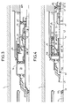
- - la figure 3 est une vue similaire illustrant l'ouverture sur courant de forte intensité,
- - la figure 4 est une vue similaire montrant la fin de la manoeuvre d'ouverture.
- La figure 1 montre une chambre de coupure comprenant une enveloppe 1, en matériau isolant tel que le céramique, remplie d'un gaz diélectrique tel que l'héxafluorure de soufre sous une pression de quelques bars. A l'intérieur de l'enveloppe, on trouve un ensemble comprenant un contact principal fixe formé de doigts de contacts 2 protégés par un capot pare-effluves 3 et un contact d'arc formé d'un cylindre ou tube métallique 4 terminé par une extrémité 4A en alliage résistant aux effets de l'arc.
- L'équipage mobile comprend un cylindre ou tube 5, métallique, servant de contact d'arc mobile, terminé par un embout 5A en alliage résistant aux effets de l'arc.
- Le tube 5 est entraîné par un tube métallique 6, par exemple en aluminium, fixé à une tige de manoeuvre non représentée. Les tubes 5 et 6 ne sont pas fixés l'un à l'autre au contraire, un certain débattement entre eux est possible ; l'entrainement se fait grâce à un redan 6B du tube 6 et à un redan 42A d'un piston 42 qui sera décrit plus loin. Le débattement est limité par une butée 6C.
- Un tube métallique 7, concentrique au tube 5, sert de contact principal mobile.
- Il porte une buse de soufflage 8 en matériau isolant. Il est en contact électrique avec un bloc métallique 9, en aluminium par exemple, solidaire de l'équipage fixe, par des doigts de contact 10.
- Le tube 5 et le tube 7 sont solidarisés par une couronne isolante 12, percée de trous 12A.
- Le volume 20 délimité par les tubes 5 et 7 est fermé par un piston fixe 14, en matériau isolant tel que le polytétrafluoroéthylène, ou autre matière maintenu en place par un tube métallique 15 fixé au bloc 9.
- On désigne par 20 le volume délimité par les tubes 5 et 7, la couronne 12 et le piston 14. Ce volume constitue le cylindre de soufflage du disjoncteur.
- Le piston 14 est percé d'orifices 16 et comprend un clapet 17 n'autorisant le passage du gaz que de l'intérieur vers l'extérieur du volume 20. Le piston 14 comprend un joint d'étanchéité 18.
- Le piston 14 est autorisé à excursionner par rapport à la pièce fixe 15. A cet effet, il est fixé à un tube 21 coulissant contre le tube 7 et possédant une butée à bille 22 et ressort 23 ou autre système coopérant avec une encoche 24 pratiquée dans le tube 15. Un ressort 25 travaillant à la compression est disposé entre une couronne 15A d'extrémité de la pièce 15 et une couronne 21A à l'extrémité du tube 21.
- Le piston 14 ne coulisse pas directement sur le tube 5 mais par l'intermédiaire d'un bloc 28 muni de contact électrique 29 et terminé par un cylindre 30 constituant l'un des contacts secondaires. L'autre contact secondaire 31 est solidaire du tube 15. Une électrode 32 est portée par un bloc métallique 33 dans le prolongement du tube 5 et séparé de celui-ci par une portion tubulaire 58 en matériau isolant.
- Le volume 35, délimité par le tube 15, le piston 14, le bloc 28 et les contacts 30 et 31, est fermé par un piston isolant 42, fixé au tube 5 et possédant un segment de guidage 43 et un clapet 44 n'autorisant le passage du gaz que de l'extérieur vers l'intérieur du volume 35.
- Le bloc 33 porte à son extrémité des trous 46. De même le tube 6 possède des trous 47. Le rôle de ces trous sera expliqué plus loin.
- La pièce 9 porte un contact 48 coopérant avec une extrémité 49 du tube 5 pour placer le bloc 33 au même potentiel que le reste de l'équipage mobile en fin de course d'ouverture.
- Une électrode 49A portée par la pièce fixe 15 permet, en fin de manoeuvre d'ouverture, de mettre le bloc 28 au potentiel de la pièce 15.
- Le fonctionnement du disjoncteur est le suivant.
- Lorsque le disjoncteur est fermé (position de la figure 1), le courant passe par les doigts 2, le tube 7, les doigts 10 et la pièce 9.
- Il s'agit des courants inférieurs ou égaux au courant nominal de l'installation. A l'ouverture du disjoncteur (figure 2), l'équipage mobile est entraîné par le tube 6. A la séparation des contacts, un arc 50 jaillit entre les contacts d'arc 4A et 5A.
- A peu près simultanément, un arc 60 s'établit entre les contacts secondaires 30 et 32, puis commute sur le contact 31. Le courant passe alors par le contact 4, l'arc 50, le tube 5, le bloc 28, le contact 30, l'arc 60, le contact 31, le tube 15 et le bloc 9. L'arc est de faible énergie et l'augmentation de pression dans le volume 35 est insuffisante pour déplacer le piston 14 par rapport au tube 15.
- La pression dans le volume 20 augmente peu en raison de l'ouverture du clapet 17.
- Le soufflage est néanmoins suffisant pour éteindre l'arc 50 au premier passage par zéro du courant. L'énergie de manoeuvre est faible.
- Il s'agit des courants de court-circuit.
- La figure 3 montre le disjoncteur en cours d'ouverture par déplacement du tube 6 vers la droite de la figure.
- L'arc 60, de très forte intensité, provoque un échauffement rapide du volume 35 et corrélativement une augmentation très importante de la pression du gaz de ce volume.
Cette augmentation de pression a trois effets :
- le premier effet est de fermer le clapet 17,
- le second effet est de déplacer le piston 14 par rapport au tube fixe 15.
La bille 22 quitte l'encoche 24 et le ressort 25 est comprimé. Le déplacement du piston, qui résulte de la superposition de deux mouvements, l'un par rapport au tube 15, l'autre par rapport à l'ensemble mobile, produit une compression très rapide du gaz du volume 20 et un soufflage très énergique. - L'allongement de l'arc, dû à la distance supplémentaire qui intervient entre les contacts 30 et 31, permet de mieux chauffer le gaz du volume 35,
- le troisième effet de l'augmentation de pression du gaz du volume 35 est d'exercer une pression importante sur le piston 42 solidaire de l'équipage mobile, ce qui apporte une énergie supplémentaire pour la manoeuvre d'ouverture du disjoncteur. - En fin de phase d'ouverture, le ressort 25 ramène le piston 14 jusqu'à ce que la bille 22 tombe dans l'encoche 24.
- En fin de mouvement d'ouverture (figure 4), le cylindre de soufflage pousse le piston 14 et fait échapper la bille 22 de son encoche 24 ; le piston 14, sous l'action du ressort 25 peut avancer jusqu'en butée 15A ; ce faisant l'électrode 30, solidaire du piston 14, se déplace également.
- La distance L2 entre l'électrode 32 et le contact auxiliaire 30 est alors inférieure à la distance L1 entre les contacts d'arc 4A et 5A.
- De la sorte, lors de l'enclenchement, aucun amorçage ne se produira dans le volume clos 35.
- Le tube 6 est actionné vers la gauche de la figure. La butée 6C entraîne le tube 5. La légère surpression dans le volume 35 s'évacue, par les trous 46 et 47 qui viennent en coincidence, vers le volume 70 intérieur au tube 5.
- En fin de manoeuvre de fermeture on retrouve la configuration de la figure 1.
- Toute résistance due à une éventuelle dépression dans la chambre 20 est évitée par l'ouverture du clapet 17.
Claims (8)
Priority Applications (1)
| Application Number | Priority Date | Filing Date | Title |
|---|---|---|---|
| AT89119712T ATE98812T1 (de) | 1988-11-02 | 1989-10-24 | Hochspannungsdruckgasschalter. |
Applications Claiming Priority (2)
| Application Number | Priority Date | Filing Date | Title |
|---|---|---|---|
| FR8814274 | 1988-11-02 | ||
| FR8814274A FR2638564B1 (fr) | 1988-11-02 | 1988-11-02 | Disjoncteur a haute tension a gaz dielectrique sous pression |
Publications (2)
| Publication Number | Publication Date |
|---|---|
| EP0367072A1 true EP0367072A1 (fr) | 1990-05-09 |
| EP0367072B1 EP0367072B1 (fr) | 1993-12-15 |
Family
ID=9371487
Family Applications (1)
| Application Number | Title | Priority Date | Filing Date |
|---|---|---|---|
| EP89119712A Expired - Lifetime EP0367072B1 (fr) | 1988-11-02 | 1989-10-24 | Disjoncteur à haute tension à gaz diélectrique sous pression |
Country Status (10)
| Country | Link |
|---|---|
| US (1) | US5001314A (fr) |
| EP (1) | EP0367072B1 (fr) |
| JP (1) | JP2579688B2 (fr) |
| CN (1) | CN1016477B (fr) |
| AT (1) | ATE98812T1 (fr) |
| BR (1) | BR8905624A (fr) |
| CA (1) | CA2001986C (fr) |
| DE (1) | DE68911479T2 (fr) |
| ES (1) | ES2047090T3 (fr) |
| FR (1) | FR2638564B1 (fr) |
Families Citing this family (14)
| Publication number | Priority date | Publication date | Assignee | Title |
|---|---|---|---|---|
| FR2661549B1 (fr) * | 1990-04-25 | 1996-07-19 | Alsthom Gec | Disjoncteur a moyenne ou haute tension a contacts d'arc en bout. |
| FR2661550B1 (fr) * | 1990-04-26 | 1992-06-12 | Alsthom Gec | Disjoncteur a haute tension a arc serie. |
| JPH06310000A (ja) * | 1993-04-20 | 1994-11-04 | Hitachi Ltd | 接地開閉装置 |
| FR2748598B1 (fr) * | 1996-05-13 | 1998-06-05 | Gec Alsthom T & D Sa | Disjoncteur a haute tension a auto-soufflage |
| FR2753834B1 (fr) * | 1996-09-23 | 1998-12-04 | Disjoncteur a haute tension avec amortisseur | |
| FR2756413B1 (fr) * | 1996-11-28 | 1998-12-31 | Gec Alsthom T & D Sa | Disjoncteur a piston semi-mobile |
| DE19953560C1 (de) * | 1999-11-03 | 2001-06-07 | Siemens Ag | Druckgas-Leistungsschalter |
| KR100475065B1 (ko) * | 2002-03-21 | 2005-03-10 | 엘지산전 주식회사 | 가스절연 차단기의 소호장치 |
| ATE458259T1 (de) | 2005-09-26 | 2010-03-15 | Abb Technology Ag | Hochspannungsschalter mit verbesserter schaltleistung |
| DE102010062343A1 (de) | 2010-12-02 | 2012-06-06 | Siemens Aktiengesellschaft | Elektrokontaktanordnung |
| WO2013087687A1 (fr) | 2011-12-13 | 2013-06-20 | Abb Technology Ag | Disjoncteur doté d'une injection de fluide |
| US10026571B1 (en) * | 2017-03-31 | 2018-07-17 | General Electric Technology Gmbh | Switching chamber for a gas-insulated circuit breaker comprising an optimized thermal channel |
| EP3503153B1 (fr) | 2017-12-22 | 2021-09-01 | ABB Power Grids Switzerland AG | Disjoncteur haute ou moyenne tension isolé au gaz |
| GB2576338A (en) * | 2018-08-15 | 2020-02-19 | Eaton Intelligent Power Ltd | Switching device and method for operating a switching device |
Citations (5)
| Publication number | Priority date | Publication date | Assignee | Title |
|---|---|---|---|---|
| DE2403300A1 (de) * | 1974-01-24 | 1975-07-31 | Bbc Brown Boveri & Cie | Elektrischer schalter |
| EP0061992A2 (fr) * | 1981-03-30 | 1982-10-06 | Ernst Slamecka | Interrupteur à piston de soufflage pour haute tension |
| EP0088442A2 (fr) * | 1982-03-09 | 1983-09-14 | Kabushiki Kaisha Toshiba | Disjoncteur à autosoufflage |
| FR2576143A1 (fr) * | 1985-01-16 | 1986-07-18 | Alsthom Atlantique | Disjoncteur a haute tension, a gaz comprime, a energie de manoeuvre assistee par l'effet thermique de l'arc et a double mouvement |
| EP0239068A1 (fr) * | 1986-03-26 | 1987-09-30 | Gec Alsthom Sa | Disjoncteur à gaz diélectrique sous pression |
-
1988
- 1988-11-02 FR FR8814274A patent/FR2638564B1/fr not_active Expired - Lifetime
-
1989
- 1989-10-24 AT AT89119712T patent/ATE98812T1/de not_active IP Right Cessation
- 1989-10-24 DE DE89119712T patent/DE68911479T2/de not_active Expired - Fee Related
- 1989-10-24 EP EP89119712A patent/EP0367072B1/fr not_active Expired - Lifetime
- 1989-10-24 ES ES89119712T patent/ES2047090T3/es not_active Expired - Lifetime
- 1989-11-01 CA CA002001986A patent/CA2001986C/fr not_active Expired - Fee Related
- 1989-11-01 BR BR898905624A patent/BR8905624A/pt not_active IP Right Cessation
- 1989-11-01 JP JP1285976A patent/JP2579688B2/ja not_active Expired - Lifetime
- 1989-11-02 US US07/430,403 patent/US5001314A/en not_active Expired - Fee Related
- 1989-11-02 CN CN89108307A patent/CN1016477B/zh not_active Expired
Patent Citations (5)
| Publication number | Priority date | Publication date | Assignee | Title |
|---|---|---|---|---|
| DE2403300A1 (de) * | 1974-01-24 | 1975-07-31 | Bbc Brown Boveri & Cie | Elektrischer schalter |
| EP0061992A2 (fr) * | 1981-03-30 | 1982-10-06 | Ernst Slamecka | Interrupteur à piston de soufflage pour haute tension |
| EP0088442A2 (fr) * | 1982-03-09 | 1983-09-14 | Kabushiki Kaisha Toshiba | Disjoncteur à autosoufflage |
| FR2576143A1 (fr) * | 1985-01-16 | 1986-07-18 | Alsthom Atlantique | Disjoncteur a haute tension, a gaz comprime, a energie de manoeuvre assistee par l'effet thermique de l'arc et a double mouvement |
| EP0239068A1 (fr) * | 1986-03-26 | 1987-09-30 | Gec Alsthom Sa | Disjoncteur à gaz diélectrique sous pression |
Also Published As
| Publication number | Publication date |
|---|---|
| CN1016477B (zh) | 1992-04-29 |
| CA2001986C (fr) | 1993-10-05 |
| CA2001986A1 (fr) | 1990-05-02 |
| EP0367072B1 (fr) | 1993-12-15 |
| FR2638564B1 (fr) | 1990-11-30 |
| US5001314A (en) | 1991-03-19 |
| BR8905624A (pt) | 1990-06-05 |
| DE68911479D1 (de) | 1994-01-27 |
| DE68911479T2 (de) | 1994-04-07 |
| ATE98812T1 (de) | 1994-01-15 |
| CN1042445A (zh) | 1990-05-23 |
| JP2579688B2 (ja) | 1997-02-05 |
| JPH02172121A (ja) | 1990-07-03 |
| ES2047090T3 (es) | 1994-02-16 |
| FR2638564A1 (fr) | 1990-05-04 |
Similar Documents
| Publication | Publication Date | Title |
|---|---|---|
| EP0517620B1 (fr) | Disjoncteur moyenne tension à énergie de commande réduite | |
| EP0367072B1 (fr) | Disjoncteur à haute tension à gaz diélectrique sous pression | |
| CA2035688C (fr) | Disjoncteur a moyenne ou haute tension a autosoufflage | |
| FR2596575A1 (fr) | Disjoncteur a gaz dielectrique sous pression | |
| CA1317619C (fr) | Disjoncteur a haute tension a gaz dielectrique utilise pour le soufflage | |
| EP0591039B1 (fr) | Disjoncteur à haute tension à auto-soufflage ayant une chambre de coupure à compression de gaz réduite | |
| EP0334181B1 (fr) | Disjoncteur à haute tension à faible énergie de manoeuvre | |
| CA2206950C (fr) | Disjoncteur a haute tension avec insertion de resistance a la fermeture. | |
| EP0239932A1 (fr) | Disjoncteur à haute tension à gaz diélectrique sous pression | |
| FR2576144A1 (fr) | Disjoncteur a haute tension, a gaz comprime, a faible energie de manoeuvre | |
| FR2733086A1 (fr) | Dispositif de coupure hybride a haute tension | |
| FR2610763A1 (fr) | Disjoncteur a faible energie de manoeuvre | |
| EP0406794B1 (fr) | Disjoncteur à haute ou moyenne tension | |
| EP0398211A1 (fr) | Disjoncteur à haute tension à gaz diélectrique de soufflage | |
| CA2041234C (fr) | Disjoncteur a haute tension a arc serie | |
| EP0021951A1 (fr) | Interrupteur à autosoufflage par aspiration | |
| BE897956A (fr) | Chambre de coupure pour disjoncteur a gaz | |
| CA2017804C (fr) | Disjoncteur a haute tension a gaz dielectrique de soufflage | |
| FR2593636A1 (fr) | Disjoncteur a hexafluorure de soufre fonctionnant dans un environnement a tres basse temperature | |
| CH688702A5 (fr) | Disjoncteur à haute tension ayant une chambre de coupure à volume de soufflage variable. | |
| FR2640420A2 (fr) | Disjoncteur a haute tension a faible energie de manoeuvre | |
| FR2646961A1 (fr) | Disjoncteur a moyenne tension a autosoufflage | |
| FR2705494A1 (fr) | Disjoncteur à manÓoeuvre assistée par voie électrodynamique. | |
| CH681751A5 (en) | High voltage circuit breaker | |
| EP0532394A1 (fr) | Dispositif de coupure sans passage naturel par zéro du courant |
Legal Events
| Date | Code | Title | Description |
|---|---|---|---|
| PUAI | Public reference made under article 153(3) epc to a published international application that has entered the european phase |
Free format text: ORIGINAL CODE: 0009012 |
|
| AK | Designated contracting states |
Kind code of ref document: A1 Designated state(s): AT BE CH DE ES FR GB GR IT LI LU NL SE |
|
| 17P | Request for examination filed |
Effective date: 19901108 |
|
| 17Q | First examination report despatched |
Effective date: 19930316 |
|
| GRAA | (expected) grant |
Free format text: ORIGINAL CODE: 0009210 |
|
| AK | Designated contracting states |
Kind code of ref document: B1 Designated state(s): AT BE CH DE ES FR GB GR IT LI LU NL SE |
|
| PG25 | Lapsed in a contracting state [announced via postgrant information from national office to epo] |
Ref country code: NL Effective date: 19931215 Ref country code: GR Free format text: LAPSE BECAUSE OF FAILURE TO SUBMIT A TRANSLATION OF THE DESCRIPTION OR TO PAY THE FEE WITHIN THE PRESCRIBED TIME-LIMIT Effective date: 19931215 Ref country code: AT Effective date: 19931215 |
|
| REF | Corresponds to: |
Ref document number: 98812 Country of ref document: AT Date of ref document: 19940115 Kind code of ref document: T |
|
| REF | Corresponds to: |
Ref document number: 68911479 Country of ref document: DE Date of ref document: 19940127 |
|
| REG | Reference to a national code |
Ref country code: ES Ref legal event code: FG2A Ref document number: 2047090 Country of ref document: ES Kind code of ref document: T3 |
|
| GBT | Gb: translation of ep patent filed (gb section 77(6)(a)/1977) |
Effective date: 19940121 |
|
| ITF | It: translation for a ep patent filed | ||
| NLV1 | Nl: lapsed or annulled due to failure to fulfill the requirements of art. 29p and 29m of the patents act | ||
| PLBE | No opposition filed within time limit |
Free format text: ORIGINAL CODE: 0009261 |
|
| STAA | Information on the status of an ep patent application or granted ep patent |
Free format text: STATUS: NO OPPOSITION FILED WITHIN TIME LIMIT |
|
| PG25 | Lapsed in a contracting state [announced via postgrant information from national office to epo] |
Ref country code: LU Free format text: LAPSE BECAUSE OF NON-PAYMENT OF DUE FEES Effective date: 19941031 Ref country code: BE Effective date: 19941031 |
|
| 26N | No opposition filed | ||
| EAL | Se: european patent in force in sweden |
Ref document number: 89119712.1 |
|
| BERE | Be: lapsed |
Owner name: S.A. GEC ALSTHOM Effective date: 19941031 |
|
| PGFP | Annual fee paid to national office [announced via postgrant information from national office to epo] |
Ref country code: GB Payment date: 19970915 Year of fee payment: 9 Ref country code: FR Payment date: 19970915 Year of fee payment: 9 |
|
| PGFP | Annual fee paid to national office [announced via postgrant information from national office to epo] |
Ref country code: DE Payment date: 19970922 Year of fee payment: 9 |
|
| PGFP | Annual fee paid to national office [announced via postgrant information from national office to epo] |
Ref country code: SE Payment date: 19970925 Year of fee payment: 9 Ref country code: CH Payment date: 19970925 Year of fee payment: 9 |
|
| PGFP | Annual fee paid to national office [announced via postgrant information from national office to epo] |
Ref country code: ES Payment date: 19971021 Year of fee payment: 9 |
|
| PG25 | Lapsed in a contracting state [announced via postgrant information from national office to epo] |
Ref country code: GB Free format text: LAPSE BECAUSE OF NON-PAYMENT OF DUE FEES Effective date: 19981024 |
|
| PG25 | Lapsed in a contracting state [announced via postgrant information from national office to epo] |
Ref country code: SE Free format text: LAPSE BECAUSE OF NON-PAYMENT OF DUE FEES Effective date: 19981025 |
|
| PG25 | Lapsed in a contracting state [announced via postgrant information from national office to epo] |
Ref country code: ES Free format text: LAPSE BECAUSE OF THE APPLICANT RENOUNCES Effective date: 19981026 |
|
| PG25 | Lapsed in a contracting state [announced via postgrant information from national office to epo] |
Ref country code: LI Free format text: LAPSE BECAUSE OF NON-PAYMENT OF DUE FEES Effective date: 19981031 Ref country code: CH Free format text: LAPSE BECAUSE OF NON-PAYMENT OF DUE FEES Effective date: 19981031 |
|
| REG | Reference to a national code |
Ref country code: CH Ref legal event code: PL |
|
| GBPC | Gb: european patent ceased through non-payment of renewal fee |
Effective date: 19981024 |
|
| EUG | Se: european patent has lapsed |
Ref document number: 89119712.1 |
|
| PG25 | Lapsed in a contracting state [announced via postgrant information from national office to epo] |
Ref country code: FR Free format text: LAPSE BECAUSE OF NON-PAYMENT OF DUE FEES Effective date: 19990630 |
|
| REG | Reference to a national code |
Ref country code: FR Ref legal event code: ST |
|
| PG25 | Lapsed in a contracting state [announced via postgrant information from national office to epo] |
Ref country code: DE Free format text: LAPSE BECAUSE OF NON-PAYMENT OF DUE FEES Effective date: 19990803 |
|
| REG | Reference to a national code |
Ref country code: ES Ref legal event code: FD2A Effective date: 20001009 |
|
| PG25 | Lapsed in a contracting state [announced via postgrant information from national office to epo] |
Ref country code: IT Free format text: LAPSE BECAUSE OF NON-PAYMENT OF DUE FEES Effective date: 20051024 |