EP0367102A2 - Avertisseur de court-circuit - Google Patents
Avertisseur de court-circuit Download PDFInfo
- Publication number
- EP0367102A2 EP0367102A2 EP89119880A EP89119880A EP0367102A2 EP 0367102 A2 EP0367102 A2 EP 0367102A2 EP 89119880 A EP89119880 A EP 89119880A EP 89119880 A EP89119880 A EP 89119880A EP 0367102 A2 EP0367102 A2 EP 0367102A2
- Authority
- EP
- European Patent Office
- Prior art keywords
- slide
- short
- switch
- trigger
- circuit
- Prior art date
- Legal status (The legal status is an assumption and is not a legal conclusion. Google has not performed a legal analysis and makes no representation as to the accuracy of the status listed.)
- Granted
Links
Images
Classifications
-
- H—ELECTRICITY
- H01—ELECTRIC ELEMENTS
- H01H—ELECTRIC SWITCHES; RELAYS; SELECTORS; EMERGENCY PROTECTIVE DEVICES
- H01H71/00—Details of the protective switches or relays covered by groups H01H73/00 - H01H83/00
- H01H71/10—Operating or release mechanisms
- H01H71/12—Automatic release mechanisms with or without manual release
- H01H71/46—Automatic release mechanisms with or without manual release having means for operating auxiliary contacts additional to the main contacts
- H01H71/462—Automatic release mechanisms with or without manual release having means for operating auxiliary contacts additional to the main contacts housed in a separate casing, juxtaposed to and having the same general contour as the main casing
Definitions
- the invention relates to a short-circuit detector for signaling overcurrent and short-circuit tripping, preferably in conjunction with a circuit breaker or motor protection switch, and the function of a short-circuit lock by manual reset on site.
- short-circuit detectors particularly if they are connected to a circuit breaker or motor protection switch, switch both in the event of a short-circuit and in the event of an overcurrent, it is important to be able to recognize the type of tripping from the outside, the short-circuit detector only detecting overcurrents above the approx. times the nominal current.
- a separate auxiliary switch can be assigned to each locking lever in such a circuit breaker.
- the invention has for its object to improve a short-circuit detector according to the preamble of claim 1 so that a high level of functions is achieved by a simple structure and the short-circuit display and the resetting can be done by hand with a single indicator plunger.
- the reset button of the short-circuit detector is connected to a switch-on slide, which is operatively connected via a deflection lever to a trigger-blocking slide which can be displaced in parallel with it, which can be displaced in the triggering direction of a triggering device of the circuit breaker or motor-protective circuit-breaker and via a trigger pin with this triggering device in the triggering direction in a positive manner is connected, there is a particularly compact design of such a short-circuit detector, since the switch-on slide and the combined trigger-lock slide can be arranged directly next to one another in the switch housing.
- a particularly reliable functioning of such a short-circuit detector is also achieved by the deflection lever, and it is also possible to arrange a test opening in the axial extension of the trigger slide on the front narrow side of the switch housing directly next to the reset button, through which the trigger slide by means of a pointed object, such as a Screwdriver or the like, even without a short circuit tripping and without the circuit breaker or motor protection switch to which the short-circuit detector is connected being supplied with current can be triggered purely mechanically by hand for test purposes.
- a pointed object such as a Screwdriver or the like
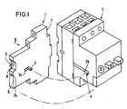
- the short-circuit detector 1 can, as shown in Fig. 1, be laterally attached to a circuit breaker or motor protection switch 2 such that it is in operative connection with a laterally protruding tripping pin 3 with a release device 4 on the circuit breaker or motor protection switch 2, which at a short-circuit or overcurrent triggering of the circuit breaker or motor protection switch 2 is moved in the triggering direction of the short-circuit detector 1.
- the short-circuit detector 1 has a manually operated reset button 5, which is arranged sunk in a recess 8 on the front narrow side 6 of the switch housing 7 such that it does not protrude beyond the level of the narrow side 6 of the housing and this level even in the OFF position thus is not interrupted by the reset button 5 even in the OFF position shown in FIGS. 1 and 4.
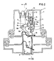
- the short-circuit detector 1 has a switch-on slide 9 which can be operated manually via the reset button 5 and which is operatively connected via a bell crank 10 to a combined trigger-lock slide 11 which can be displaced in parallel therewith stands, which is displaceable in the direction of displacement 12 (FIG. 4) of the tripping device 4 of the circuit breaker or motor protection switch 2 and is positively connected to this tripping device 4 in the tripping direction 12 via a tripping pin 3.
- the bell crank 10 is designed as a rocker such that the switch-on slide 9 and the combined trigger-lock slide 11 can be moved in opposite directions parallel to one another. It is pivotally mounted between the switch-on slide 9 and the parallel trigger-lock slide 11 about a pivot pin 10a fixed to the housing and is pivotably connected to the switch-on slide 9 as well as to the trigger-block valve 11 via slot-and-pin connections with play.
- the deflection lever 10 has two oblong holes 10b, 10c, which run parallel to one another in relation to its longitudinal axis, for the engagement of two driving pins 9a, 11a, which project to the side from the switch-on slide 9 and from the release lock slide 11.
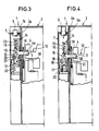
- the combined trigger-blocking slide 11 is formed in two parts and consists of a on the switch housing 7 in lateral parallel guides 13 parallel to the switch-on slide About 9 displaceable trigger slide 14 and a locking slide 16 telescopically displaceable therebetween between lateral guide cheeks 15, which is in the ON position of the trigger slide 14 in a first locking position, from which it can be moved into a position after releasing a lock by moving the trigger slide 14 , in which the switch-on slide 9 has been moved via the switch lever 10 from its ON position shown in FIGS. 2 and 3 to its OFF position in FIG. 4.
- the trigger slide 14 on the housing 7 of the short-circuit detector 1 is guided in the triggering direction 12 of the triggering device 4 on the associated circuit breaker 1 and engages with its trigger pin 3, which passes through the housing walls 7a, 2a of the switches 1, 2 mounted directly next to one another in elongated holes 3a, 3b into a recess 4a on the triggering device 4 of the circuit breaker or motor protection switch 2.
- the locking slide 16 of the short-circuit detector 1 is displaceably arranged in the triggering direction 12 of the trigger slide 14 in its axial extension or coaxially to the trigger slide 14 in the switch housing 7 and engages with a pawl 17 which rests transversely to the triggering direction 12 and counteracts a web-shaped abutment 18 on the switch housing 7 the triggering direction 12 locking hook-shaped.
- the web-shaped abutment 18 is formed in the embodiment shown from the edge of the recess or opening 19 for the trigger pin 3, which protrudes laterally from the trigger slide 14 of the short-circuit detector 1 and is in operative connection with the trigger device 4 on the power or motor protection switch 2.
- the trigger slide 14 and the pawl 17 on the locking slide 16 have transverse to the triggering direction 12 of the short-circuit detector 1 parallel inclined surfaces 20, 21 which are inclined so that the pawl 17 is pushed aside when the trigger slide 14 is moved and with it Locking lug is released from the abutment web 18 or from the lower edge of the recess 19 on the switch housing 7, so that the locking slide 16 together with the release slide 14 can reach the OFF position of the short-circuit detector 1 from FIG. 4.
- the locking slide 16 is also under the action of a tension spring 22, which moves it after releasing the lock due to the displacement of the trigger slide 14 together with the bell crank 10 in the switch-off position and holds it in this position until it is actuated by the reset button 5 via the switch-on slide 9 and the bell crank 10 has been moved back into its locking position of FIGS. 2 and 3.
- a test opening 24 is arranged in the axial extension of the trigger slide 14 on the front narrow side 6 of the switch housing 7, through which the trigger slide 14 is by means of a sharp object, such as a screwdriver or the like, even without a short-circuit release and without the circuit breaker or motor protection switch 2, with which the short-circuit detector 1 is connected, supplied with current, can be triggered purely mechanically by hand for test purposes.
- the switch-on slide 9 is connected to at least two counter-acting auxiliary switches, a break contact 25 and a make contact 26.
Landscapes
- Switch Cases, Indication, And Locking (AREA)
- Breakers (AREA)
- Fire-Detection Mechanisms (AREA)
- Burglar Alarm Systems (AREA)
Applications Claiming Priority (2)
| Application Number | Priority Date | Filing Date | Title |
|---|---|---|---|
| DE3837461 | 1988-11-04 | ||
| DE3837461A DE3837461A1 (de) | 1988-11-04 | 1988-11-04 | Kurzschlussmelder |
Publications (3)
| Publication Number | Publication Date |
|---|---|
| EP0367102A2 true EP0367102A2 (fr) | 1990-05-09 |
| EP0367102A3 EP0367102A3 (fr) | 1991-12-04 |
| EP0367102B1 EP0367102B1 (fr) | 1995-06-14 |
Family
ID=6366488
Family Applications (1)
| Application Number | Title | Priority Date | Filing Date |
|---|---|---|---|
| EP89119880A Expired - Lifetime EP0367102B1 (fr) | 1988-11-04 | 1989-10-26 | Avertisseur de court-circuit |
Country Status (3)
| Country | Link |
|---|---|
| EP (1) | EP0367102B1 (fr) |
| AT (1) | ATE123902T1 (fr) |
| DE (2) | DE3837461A1 (fr) |
Cited By (17)
| Publication number | Priority date | Publication date | Assignee | Title |
|---|---|---|---|---|
| FR2674370A1 (fr) * | 1991-03-21 | 1992-09-25 | Telemecanique | Appareil interrupteur de protection accoupable a un module de commande et/ou a un module de signalisation. |
| FR2684231A1 (fr) * | 1991-11-22 | 1993-05-28 | Hager Electro | Appareils auxiliaires de disjoncteurs electriques. |
| EP0583762A1 (fr) * | 1992-08-20 | 1994-02-23 | Moeller GmbH | Dispositif de commutation |
| EP0612089A3 (fr) * | 1993-02-17 | 1994-12-21 | Kloeckner Moeller Gmbh | Dispositif de commutation pour disjoncteurs. |
| US6031195A (en) * | 1997-07-14 | 2000-02-29 | Allen-Bradley Company, Llc | Latching mechanism for an electrical overload protection switch, in particular for a motor-protection circuit breaker |
| EP0949647A3 (fr) * | 1998-04-09 | 2000-05-10 | Eaton Corporation | Indicateur de déclenchement et ensemble interrupteur de signalisation |
| EP1315190A3 (fr) * | 2001-11-24 | 2005-02-02 | Moeller GmbH | Dispositif de test avec indicateur de court-circuit |
| FR2859570A1 (fr) * | 2003-09-04 | 2005-03-11 | Fuji Elec Fa Components & Sys | Unite de commutation auxiliaire pour un disjoncteur |
| EP1659602A2 (fr) | 2004-11-23 | 2006-05-24 | ABB PATENT GmbH | Dispositif d'affichage de déclenchement d'un disjoncteur à cause d'un courant de court-circuit |
| EP1670014A1 (fr) * | 2004-12-10 | 2006-06-14 | EATON Corporation | Procédé pour déclencher une fonction d'essai d'un dispositif de commutation électrique et dispositif de commutation électrique l'utilisant |
| EP1659603A3 (fr) * | 2004-11-23 | 2009-12-30 | ABB PATENT GmbH | Dispositif d'affichage et signalisation de déclenchement d'un disjoncteur à cause d'un courant de court-circuit |
| CN103311057A (zh) * | 2012-03-08 | 2013-09-18 | 西门子公司 | 用于电的开关设备的短路警报模块以及电的开关设备 |
| EP2911176A1 (fr) * | 2014-02-17 | 2015-08-26 | Abb Ag | Commutateur auxiliaire à touche d'essai |
| US9853400B1 (en) | 2016-11-01 | 2017-12-26 | International Business Machines Corporation | Electrical arc protection using a trip jumper |
| US9893455B1 (en) | 2016-11-01 | 2018-02-13 | International Business Machines Corporation | Electrical arc protection using a trip contact |
| US10122123B1 (en) | 2017-07-07 | 2018-11-06 | International Business Machines Corporation | Electrical arc protection using a rotational shield |
| DE102023202388A1 (de) * | 2023-03-16 | 2024-09-19 | Siemens Aktiengesellschaft | Geräte-Modul, Reiheneinbaugerät und Kontaktfeder |
Families Citing this family (2)
| Publication number | Priority date | Publication date | Assignee | Title |
|---|---|---|---|---|
| DE102010019741B4 (de) * | 2010-05-07 | 2022-05-05 | Siemens Aktiengesellschaft | Schaltmechanik für einen Fehlerstromschutzschalter sowie Fehlerstromschutzschalter |
| DE102016214681B4 (de) * | 2016-08-08 | 2018-07-26 | Audi Ag | Betätigungsvorrichtung für ein Kraftfahrzeug |
Family Cites Families (3)
| Publication number | Priority date | Publication date | Assignee | Title |
|---|---|---|---|---|
| DE3014553C2 (de) * | 1980-04-16 | 1984-03-29 | Condor-Werk Gebr. Frede KG Elektro- und Maschinenfabrik, 4722 Ennigerloh | Hilfsschalter zur Befestigung an handbetätigten Schutzschaltgeräten |
| DE3402850A1 (de) * | 1984-01-27 | 1985-08-01 | Siemens AG, 1000 Berlin und 8000 München | Schutzschalter mit ueberstrom- und kurzschlussausloesevorrichtung |
| DE3603945A1 (de) * | 1986-02-07 | 1987-08-13 | Siemens Ag | Anbauschalter fuer schutzschalter |
-
1988
- 1988-11-04 DE DE3837461A patent/DE3837461A1/de not_active Withdrawn
-
1989
- 1989-10-26 EP EP89119880A patent/EP0367102B1/fr not_active Expired - Lifetime
- 1989-10-26 DE DE58909294T patent/DE58909294D1/de not_active Expired - Fee Related
- 1989-10-26 AT AT89119880T patent/ATE123902T1/de not_active IP Right Cessation
Cited By (20)
| Publication number | Priority date | Publication date | Assignee | Title |
|---|---|---|---|---|
| FR2674370A1 (fr) * | 1991-03-21 | 1992-09-25 | Telemecanique | Appareil interrupteur de protection accoupable a un module de commande et/ou a un module de signalisation. |
| FR2684231A1 (fr) * | 1991-11-22 | 1993-05-28 | Hager Electro | Appareils auxiliaires de disjoncteurs electriques. |
| EP0583762A1 (fr) * | 1992-08-20 | 1994-02-23 | Moeller GmbH | Dispositif de commutation |
| EP0612089A3 (fr) * | 1993-02-17 | 1994-12-21 | Kloeckner Moeller Gmbh | Dispositif de commutation pour disjoncteurs. |
| US6031195A (en) * | 1997-07-14 | 2000-02-29 | Allen-Bradley Company, Llc | Latching mechanism for an electrical overload protection switch, in particular for a motor-protection circuit breaker |
| EP0949647A3 (fr) * | 1998-04-09 | 2000-05-10 | Eaton Corporation | Indicateur de déclenchement et ensemble interrupteur de signalisation |
| EP1315190A3 (fr) * | 2001-11-24 | 2005-02-02 | Moeller GmbH | Dispositif de test avec indicateur de court-circuit |
| FR2859570A1 (fr) * | 2003-09-04 | 2005-03-11 | Fuji Elec Fa Components & Sys | Unite de commutation auxiliaire pour un disjoncteur |
| EP1659602A3 (fr) * | 2004-11-23 | 2009-12-30 | ABB PATENT GmbH | Dispositif d'affichage de déclenchement d'un disjoncteur à cause d'un courant de court-circuit |
| EP1659602A2 (fr) | 2004-11-23 | 2006-05-24 | ABB PATENT GmbH | Dispositif d'affichage de déclenchement d'un disjoncteur à cause d'un courant de court-circuit |
| EP1659603A3 (fr) * | 2004-11-23 | 2009-12-30 | ABB PATENT GmbH | Dispositif d'affichage et signalisation de déclenchement d'un disjoncteur à cause d'un courant de court-circuit |
| EP1670014A1 (fr) * | 2004-12-10 | 2006-06-14 | EATON Corporation | Procédé pour déclencher une fonction d'essai d'un dispositif de commutation électrique et dispositif de commutation électrique l'utilisant |
| CN103311057A (zh) * | 2012-03-08 | 2013-09-18 | 西门子公司 | 用于电的开关设备的短路警报模块以及电的开关设备 |
| EP2911176A1 (fr) * | 2014-02-17 | 2015-08-26 | Abb Ag | Commutateur auxiliaire à touche d'essai |
| US9853400B1 (en) | 2016-11-01 | 2017-12-26 | International Business Machines Corporation | Electrical arc protection using a trip jumper |
| US9893455B1 (en) | 2016-11-01 | 2018-02-13 | International Business Machines Corporation | Electrical arc protection using a trip contact |
| US10230193B2 (en) | 2016-11-01 | 2019-03-12 | International Business Machines Corporation | Electrical arc protection using a trip contact |
| US10229806B2 (en) | 2016-11-01 | 2019-03-12 | International Business Machines Corporation | Electrical arc protection using a trip jumper |
| US10122123B1 (en) | 2017-07-07 | 2018-11-06 | International Business Machines Corporation | Electrical arc protection using a rotational shield |
| DE102023202388A1 (de) * | 2023-03-16 | 2024-09-19 | Siemens Aktiengesellschaft | Geräte-Modul, Reiheneinbaugerät und Kontaktfeder |
Also Published As
| Publication number | Publication date |
|---|---|
| DE58909294D1 (de) | 1995-07-20 |
| EP0367102B1 (fr) | 1995-06-14 |
| EP0367102A3 (fr) | 1991-12-04 |
| ATE123902T1 (de) | 1995-06-15 |
| DE3837461A1 (de) | 1990-05-10 |
Similar Documents
| Publication | Publication Date | Title |
|---|---|---|
| EP0367102B1 (fr) | Avertisseur de court-circuit | |
| DE68912738T2 (de) | Modulschützschalter mit Hilfsauslöseblock mit einer automatischen oder unabhängigen Wiedereinschaltung. | |
| EP1203385B1 (fr) | Ensemble coupe-circuit multipolaire pour jeux de barres collectrices | |
| DE2438314C2 (de) | Fehlerstromschutzschalter mit einer leicht an einen Selbstschalter kuppelbaren Fehlerstromschutzeinheit | |
| DE670790C (de) | Thermisch wirkender Selbstschalter | |
| DE2835354C2 (de) | Sprungkontakt-Schutzschalter | |
| DE2403839C2 (de) | Stromkreisunterbrecher mit ein freigebbares Element verriegelnder Verriegelungsvorrichtung | |
| EP0892420B1 (fr) | Discontacteur à maximum avec cliquet pour la protection des moteurs | |
| DE2504954B2 (de) | Mechanisches sprungwerk, insbesondere fuer kleine hochleistungs-selbstschalter | |
| DE4208716C2 (de) | Schutzschaltgerät | |
| DE3037355C2 (de) | Schutzschalter kompakter Bauart mit einem Auslösestift | |
| DE2523507A1 (de) | Ausschalter | |
| DE3212474C2 (de) | Überstromschutzschalter | |
| DE3119165C2 (de) | Selbstschalter als Baueinheit aus einem Leitungsschutzschalter sowie Hilfs- und Signalschaltern | |
| DE3341874C1 (de) | Schalteranordnung mit Nullspannungsauslösung | |
| DE3213493C2 (fr) | ||
| EP1671342B1 (fr) | Disjoncteur | |
| EP0630035B1 (fr) | Interrupteur auxiliaire et de signalisation pour appareils interrupteurs de protection | |
| EP0271669B1 (fr) | Mécanisme pour un disjoncteur à courant de défaut à la terre combiné avec un disjoncteur de ligne | |
| DE2348568A1 (de) | Sicherungsautomat | |
| EP0302249B1 (fr) | Disjoncteur à maximum de courant commandé par un bouton-poussoir | |
| DE3402850C2 (fr) | ||
| DE2633774C3 (de) | Thermisches Überstromrelais | |
| DE1538452C (de) | Druckknopfbetatigter Uberstromschal ter mit thermischer und/oder elektromagne tischer Auslosung | |
| EP1329923A2 (fr) | Disjoncteur à structure simplifiée |
Legal Events
| Date | Code | Title | Description |
|---|---|---|---|
| PUAI | Public reference made under article 153(3) epc to a published international application that has entered the european phase |
Free format text: ORIGINAL CODE: 0009012 |
|
| AK | Designated contracting states |
Kind code of ref document: A2 Designated state(s): AT BE CH DE ES FR GB IT LI NL SE |
|
| RAP1 | Party data changed (applicant data changed or rights of an application transferred) |
Owner name: KLOECKNER-MOELLER GMBH |
|
| PUAL | Search report despatched |
Free format text: ORIGINAL CODE: 0009013 |
|
| AK | Designated contracting states |
Kind code of ref document: A3 Designated state(s): AT BE CH DE ES FR GB IT LI NL SE |
|
| 17P | Request for examination filed |
Effective date: 19920213 |
|
| 17Q | First examination report despatched |
Effective date: 19940121 |
|
| GRAA | (expected) grant |
Free format text: ORIGINAL CODE: 0009210 |
|
| AK | Designated contracting states |
Kind code of ref document: B1 Designated state(s): AT BE CH DE ES FR GB IT LI NL SE |
|
| PG25 | Lapsed in a contracting state [announced via postgrant information from national office to epo] |
Ref country code: IT Free format text: LAPSE BECAUSE OF FAILURE TO SUBMIT A TRANSLATION OF THE DESCRIPTION OR TO PAY THE FEE WITHIN THE PRE;WARNING: LAPSES OF ITALIAN PATENTS WITH EFFECTIVE DATE BEFORE 2007 MAY HAVE OCCURRED AT ANY TIME BEFORE 2007. THE CORRECT EFFECTIVE DATE MAY BE DIFFERENT FROM THE ONE RECORDED.SCRIBED TIME-LIMIT Effective date: 19950614 Ref country code: ES Free format text: THE PATENT HAS BEEN ANNULLED BY A DECISION OF A NATIONAL AUTHORITY Effective date: 19950614 Ref country code: GB Effective date: 19950614 Ref country code: BE Effective date: 19950614 Ref country code: NL Free format text: LAPSE BECAUSE OF NON-PAYMENT OF DUE FEES Effective date: 19950614 |
|
| REF | Corresponds to: |
Ref document number: 123902 Country of ref document: AT Date of ref document: 19950615 Kind code of ref document: T |
|
| REF | Corresponds to: |
Ref document number: 58909294 Country of ref document: DE Date of ref document: 19950720 |
|
| PG25 | Lapsed in a contracting state [announced via postgrant information from national office to epo] |
Ref country code: SE Effective date: 19950914 |
|
| ET | Fr: translation filed | ||
| PG25 | Lapsed in a contracting state [announced via postgrant information from national office to epo] |
Ref country code: AT Effective date: 19951026 |
|
| PG25 | Lapsed in a contracting state [announced via postgrant information from national office to epo] |
Ref country code: CH Effective date: 19951031 Ref country code: LI Effective date: 19951031 |
|
| GBV | Gb: ep patent (uk) treated as always having been void in accordance with gb section 77(7)/1977 [no translation filed] |
Effective date: 19950614 |
|
| NLV1 | Nl: lapsed or annulled due to failure to fulfill the requirements of art. 29p and 29m of the patents act | ||
| PLBE | No opposition filed within time limit |
Free format text: ORIGINAL CODE: 0009261 |
|
| STAA | Information on the status of an ep patent application or granted ep patent |
Free format text: STATUS: NO OPPOSITION FILED WITHIN TIME LIMIT |
|
| 26N | No opposition filed | ||
| REG | Reference to a national code |
Ref country code: CH Ref legal event code: PL |
|
| PGFP | Annual fee paid to national office [announced via postgrant information from national office to epo] |
Ref country code: DE Payment date: 19971029 Year of fee payment: 9 |
|
| PGFP | Annual fee paid to national office [announced via postgrant information from national office to epo] |
Ref country code: FR Payment date: 19981021 Year of fee payment: 10 |
|
| PG25 | Lapsed in a contracting state [announced via postgrant information from national office to epo] |
Ref country code: DE Free format text: LAPSE BECAUSE OF NON-PAYMENT OF DUE FEES Effective date: 19990803 |
|
| PG25 | Lapsed in a contracting state [announced via postgrant information from national office to epo] |
Ref country code: FR Free format text: LAPSE BECAUSE OF NON-PAYMENT OF DUE FEES Effective date: 20000630 |
|
| REG | Reference to a national code |
Ref country code: FR Ref legal event code: ST |