EP0367125B1 - Méthode et dispositif pour le nettoyage, des objets avec des dissolvants nuisibles à l'environnement, notamment des carbures d'hydrogène halogénés - Google Patents
Méthode et dispositif pour le nettoyage, des objets avec des dissolvants nuisibles à l'environnement, notamment des carbures d'hydrogène halogénés Download PDFInfo
- Publication number
- EP0367125B1 EP0367125B1 EP89119946A EP89119946A EP0367125B1 EP 0367125 B1 EP0367125 B1 EP 0367125B1 EP 89119946 A EP89119946 A EP 89119946A EP 89119946 A EP89119946 A EP 89119946A EP 0367125 B1 EP0367125 B1 EP 0367125B1
- Authority
- EP
- European Patent Office
- Prior art keywords
- solvent
- cleaning
- storage
- handling container
- cleaned
- Prior art date
- Legal status (The legal status is an assumption and is not a legal conclusion. Google has not performed a legal analysis and makes no representation as to the accuracy of the status listed.)
- Expired - Lifetime
Links
- 239000002904 solvent Substances 0.000 title claims abstract description 113
- 238000004140 cleaning Methods 0.000 title claims abstract description 45
- 238000000034 method Methods 0.000 title claims abstract description 22
- 229910052736 halogen Inorganic materials 0.000 title 1
- -1 halogen hydrocarbons Chemical class 0.000 title 1
- 229930195733 hydrocarbon Natural products 0.000 title 1
- 239000012298 atmosphere Substances 0.000 claims abstract description 5
- 230000008878 coupling Effects 0.000 claims description 9
- 238000010168 coupling process Methods 0.000 claims description 9
- 238000005859 coupling reaction Methods 0.000 claims description 9
- 239000007921 spray Substances 0.000 claims description 9
- 239000012459 cleaning agent Substances 0.000 claims description 6
- 150000005826 halohydrocarbons Chemical class 0.000 claims 1
- 230000010355 oscillation Effects 0.000 claims 1
- 238000011084 recovery Methods 0.000 abstract description 4
- 150000008282 halocarbons Chemical class 0.000 abstract description 3
- 239000003570 air Substances 0.000 description 11
- OKTJSMMVPCPJKN-UHFFFAOYSA-N Carbon Chemical compound [C] OKTJSMMVPCPJKN-UHFFFAOYSA-N 0.000 description 4
- 239000003795 chemical substances by application Substances 0.000 description 3
- 238000011109 contamination Methods 0.000 description 3
- 231100001261 hazardous Toxicity 0.000 description 3
- 239000000463 material Substances 0.000 description 3
- 239000000126 substance Substances 0.000 description 3
- 239000000853 adhesive Substances 0.000 description 2
- 230000001070 adhesive effect Effects 0.000 description 2
- 239000011248 coating agent Substances 0.000 description 2
- 238000000576 coating method Methods 0.000 description 2
- 230000000694 effects Effects 0.000 description 2
- 239000011521 glass Substances 0.000 description 2
- 230000008929 regeneration Effects 0.000 description 2
- 238000011069 regeneration method Methods 0.000 description 2
- 239000012080 ambient air Substances 0.000 description 1
- 238000005260 corrosion Methods 0.000 description 1
- 230000007613 environmental effect Effects 0.000 description 1
- 238000003912 environmental pollution Methods 0.000 description 1
- 230000002349 favourable effect Effects 0.000 description 1
- 230000009969 flowable effect Effects 0.000 description 1
- 239000006260 foam Substances 0.000 description 1
- 239000003673 groundwater Substances 0.000 description 1
- 238000003754 machining Methods 0.000 description 1
- 239000003960 organic solvent Substances 0.000 description 1
- 239000003973 paint Substances 0.000 description 1
- 238000004064 recycling Methods 0.000 description 1
- 230000001172 regenerating effect Effects 0.000 description 1
- 238000003303 reheating Methods 0.000 description 1
Images
Classifications
-
- C—CHEMISTRY; METALLURGY
- C23—COATING METALLIC MATERIAL; COATING MATERIAL WITH METALLIC MATERIAL; CHEMICAL SURFACE TREATMENT; DIFFUSION TREATMENT OF METALLIC MATERIAL; COATING BY VACUUM EVAPORATION, BY SPUTTERING, BY ION IMPLANTATION OR BY CHEMICAL VAPOUR DEPOSITION, IN GENERAL; INHIBITING CORROSION OF METALLIC MATERIAL OR INCRUSTATION IN GENERAL
- C23G—CLEANING OR DE-GREASING OF METALLIC MATERIAL BY CHEMICAL METHODS OTHER THAN ELECTROLYSIS
- C23G5/00—Cleaning or de-greasing metallic material by other methods; Apparatus for cleaning or de-greasing metallic material with organic solvents
- C23G5/02—Cleaning or de-greasing metallic material by other methods; Apparatus for cleaning or de-greasing metallic material with organic solvents using organic solvents
- C23G5/04—Apparatus
-
- B—PERFORMING OPERATIONS; TRANSPORTING
- B65—CONVEYING; PACKING; STORING; HANDLING THIN OR FILAMENTARY MATERIAL
- B65D—CONTAINERS FOR STORAGE OR TRANSPORT OF ARTICLES OR MATERIALS, e.g. BAGS, BARRELS, BOTTLES, BOXES, CANS, CARTONS, CRATES, DRUMS, JARS, TANKS, HOPPERS, FORWARDING CONTAINERS; ACCESSORIES, CLOSURES, OR FITTINGS THEREFOR; PACKAGING ELEMENTS; PACKAGES
- B65D88/00—Large containers
- B65D88/02—Large containers rigid
-
- B—PERFORMING OPERATIONS; TRANSPORTING
- B08—CLEANING
- B08B—CLEANING IN GENERAL; PREVENTION OF FOULING IN GENERAL
- B08B3/00—Cleaning by methods involving the use or presence of liquid or steam
- B08B3/006—Cabinets or cupboards specially adapted for cleaning articles by hand
Definitions
- the invention relates to a method for cleaning objects with environmentally hazardous solvents, in particular halogenated hydrocarbons of the type specified in the preamble of claim 1.
- a procedure with hot solvent in which a processing space can alternately be flooded with solvent from different tanks, which can then alternatively be returned to the same collecting tank or to an adjacent tank after completion of the cleaning process.
- the solvent used becomes more and more contaminated from cleaning process to cleaning process and the cleaning effect can only be as good as the current degree of contamination of the solvent used allows.
- a treatment with hot solvents is known which condenses recovery via heat exchangers. This is also done there in a closed system to recover the cleaning agent for recovery and reheating. In principle, fresh or recondensed fresh solvent is always used with very high energy expenditure; Pre-cleaning stages with lightly contaminated solvents are not provided there.
- the object of the invention is to provide a solution which simplifies the transport and handling of such solvents, at the same time reducing the risk to people and the environment to the lowest possible level or completely avoiding them, and with in particular optimal use of the solvent and recovery of the solvent is available.
- this object is achieved according to the invention in that at least one storage chamber is assigned to the processing space for storing partially soiled solvents, with a final cleaning step with fresh solvent from the corresponding storage tank being carried out after carrying out one or more pre-cleaning cycles after the cleaning process has ended, it is passed into the storage chamber of the handling container and heavily soiled pre-cleaning agent is conveyed into the collecting tank, and that the gas atmosphere in the processing space is filtered and cleaned before the cleaned objects are removed.
- a very special advantage of the invention lies in the optimal use of a solvent by the partial removal or the removal of portions of solvent from the storage tank for fresh solvent, the availability of this solvent in the area of the processing space until it is so dirty that it regeneration. If this level of contamination is reached, it is conveyed into the collecting tank. This ensures that a comparatively pure and completely pure solvent is always available for the user of the system for final cleaning, as a result of which a standardized cleaning result can be achieved.
- At least two storage chambers next to the storage tank for fresh solvent and the collecting tank for heavily contaminated solvent are assigned to the processing space, pre-cleaning steps with differently contaminated solvents are carried out from the storage chambers and the feed from the storage chamber with the most contaminated solvents in the catch tank.
- This configuration makes economic process management in particular possible and treats the amounts of solvents carefully, with the frequency of regenerating contaminated solvents being further reduced.
- several corresponding storage chambers can also be provided, each of which can hold a volume of solvent required for the treatment.
- the degree of soiling in the chambers can be higher in stages. The most contaminated solvent is prewashed in a prewash stage, and the subsequent, somewhat cleaner solvent is used for a second prewash stage until the final cleaning is finally carried out with the cleanest solvent. If the degree of soiling is so high in the heavily soiled stage that it is no longer sensible to prewash it, this last amount of solvent is then returned to the collecting tank and a very clean, fresh amount of solvent is fed back into the system.
- storage chambers can also be filled with chemically similar substances for application.
- workpieces can initially be cleaned and, after the cleaning process has ended, an anti-corrosion agent can be applied to the cleaned objects from the application chamber Release agent or a paint coating, an adhesive coating or the like. Without the objects to be treated would have to be removed from the system.
- the invention also provides a device which, in addition to a larger-volume storage tank for exclusively fresh solvent, provides a collecting tank for heavily soiled solvents extracted from the cleaning process and that at least one storage chamber for less soiled solvents for carrying out pre-cleaning operations is assigned to the processing space .
- Such a device has the advantage that larger amounts of solvent are available at the same time but it can be ensured that only a small-volume supply is currently available for the user, so that even improper handling cannot spill even small amounts.
- the storage tank for fresh solvent, the storage tank (s) for solvent for pre-cleaning stages and the storage tank for used solvent are coupled to one another by means of lines and overflows.
- a special embodiment of the invention consists in that the handling container is assigned at least two storage chambers for clean or slightly contaminated solvent on the one hand and for heavily contaminated solvent on the other.
- the handling container is first flooded with the amount of solvent assigned to it and after corresponding treatment cycles and thus corresponding contamination of the solvent, it can then be drained into the collecting container. Now the handling container can be flooded again with fresh solvent.
- the effective positive coupling of the containers enables control in such a way that a backflow of used solvent into fresh solvent is avoided, as is overfilling of the handling container.
- the invention also provides an overflow line to the collecting tank. This ensures that e.g. If the amount of fresh solvent is too large, the excess solvent is fed directly into the collecting tank, i.e. that the risk is avoided that the handling container overflows, for example.
- the earth connection also provides for the handling container to be provided with a drip zone and / or an overflow gutter or drip gutter is.
- the draining zone can be designed so that the solvent drips directly back into the handling container or directly into the collecting tank.
- the gas space of the handling container is provided with a circulating air cleaning device, which is provided in particular if larger-volume treatment rooms are also provided which are closed during the entire processing time.
- the invention also provides that a circulation device and / or a spray device and / or an ultrasonic vibrating device is provided in the handling container, i.e. Tools that are known in a different context.
- the invention also provides that the two storage tanks are arranged on a conveyor pallet and / or that the handling container is formed in one piece with the conveyor pallet and the tanks arranged thereon.
- the solvents can be optimally reprocessed, i.e.
- the environment is also relieved in this respect, the processing companies can also remove the residues in the solvent.
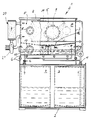
- this shows a side view of a larger-volume device after earth connection.
- the device has on a transport pallet 2 a larger-volume storage tank 3 for fresh solvent, a collecting tank 4 for used solvent, and a handling tank, generally designated 5, which in the example shown is on a Support frame 6 is arranged above the storage tank 3 and the collecting tank 4.
- the handling container 5 is designed as a closed housing 7 with a lid 8.
- the handling container 5 has two storage chambers 3a and 4a in the bottom area, it being noted at this point that it can also be more than two such storage chambers. These storage chambers have a volume which is sufficient to hold a quantity of solvent, whether soiled or less soiled or pure, which is sufficient for the entire machining process.
- At least one overflow nozzle 10 is provided in the handling container 4 for level control.
- the storage tank 3 is connected to the handling container 5 via a coupling 11 and a coupling tube.
- the handling container 5 can also be coupled to the collecting tank 4 with a further coupling 12 in the coupling tube.
- the couplings 11 and 12 can be electrically connected to a computer, not shown.
- Spray nozzles 15 are provided in order to spray the workpieces to be treated.
- the sprayed solvent is returned via a drip zone or the inclined floor 16 into the respective lower storage chambers 3a or 4a of the container 5, the fill level can be monitored via sight glasses 17 as well as the spray activity through sight glasses 18, which is only indicated in the figures is.
- the processing gas space of the container 5, generally designated 19, is coupled to a circulating air cleaning device 20.
- the air is passed through a suction fan 21, for example through an activated carbon filter, and pumped back into the space 19.
- a condensing device for solvents (not shown in more detail) can be provided with the possibility of returning the solvent, either directly into one of the storage tanks 3 or 4 or into the container 5 if the container 5 is very large in volume.
- Both the cover 8 and the locking device can be equipped electronically in such a way that, for example, the locks are only released when the coupling between the storage tank 3 and the handling container 5 and the collecting tank 4 is present.
- the circuit can be made such that when opening the cover 8 can only be opened first when the air in the gas space 19 is cleaned by a swirl caused by lifting the cover to avoid the air above the solvent zone. When closing, the circuit can then be reversed so that the handling container 5 can only be filled with solvent when the handling container is covered by the horizontal cover 8.
- the device works as follows: First, the workpiece or workpieces 9 to be treated is introduced into the gas space 19 of the container 5. Assuming that neither of the two storage chambers 3a or 4a are filled, one of the chambers is first flooded with such an amount of solvent that is sufficient for cleaning. Then the connection between the storage tank 3 and the handling container 5 is blocked.
- the workpiece 9 is now sprayed from the storage chamber 3a via the spray device 15.
- the solvent always flows back into the storage chamber 3a.
- the cleaned workpiece 9 can be removed.
- the storage chamber 3a remains closed to the environment with the now somewhat dirty solvent.
- a preliminary cleaning can now be carried out start over the solvent in chamber 3a.
- the pre-cleaning agent is finally fed into the collecting tank 4.
- the system can be replaced and the contaminated solvent can be regenerated. This also applies to filters that can also be regenerated when the solvent is recovered.
- the lid can be dispensed with, where appropriate, an annular suction of the container air can be provided u.
- the device can also be used, for example, automatically operating spray heads or the like on robot arms which Adhesive, foam or similar hardening materials have to be processed during the inactive times of the spray heads, for example in such a way that the robot arm is introduced into the gas space 19 of the container 5 via a lock, cleaned after the locks have been locked and if necessary is dried with air and can then be moved back to the working position via the lock without causing environmental pollution.
Landscapes
- Engineering & Computer Science (AREA)
- Mechanical Engineering (AREA)
- Chemical & Material Sciences (AREA)
- Chemical Kinetics & Catalysis (AREA)
- General Chemical & Material Sciences (AREA)
- Materials Engineering (AREA)
- Metallurgy (AREA)
- Organic Chemistry (AREA)
- Cleaning By Liquid Or Steam (AREA)
- Detergent Compositions (AREA)
- Cleaning Or Drying Semiconductors (AREA)
- Cleaning And De-Greasing Of Metallic Materials By Chemical Methods (AREA)
Claims (11)
- Procédé de nettoyage d'objets avec des solvants dangereux pour l'environnement, en particulier des hydrocarbures halogénés, dans un système fermé pendant l'opération de nettoyage, dans lequel on transporte un solvant d'une citerne de réserve (3) dans un compartiment de traitement (19) d'un récipient de maniement (5), on imprègne ensuite les objets (9) à nettoyer et on les nettoie avec le solvant se trouvant dans le compartiment de traitement (19), le solvant étant renvoyé du compartiment de traitement (19) dans un réservoir collecteur (4) après une ou plusieurs opérations de nettoyage,
caractérisé en ce que, pour la mise en réserve de solvants partiellement salis, on adjoint au compartiment de traitement (19) au moins une chambre de réserve (3a), ce qui fait que, après la réalisation d'une ou plusieurs opérations de lavage, on effectue une étape de lavage final avec du solvant frais issu de la citerne de réserve (3) correspondante, on envoie ce solvant après la fin du processus de lavage dans la chambre de réserve (3a) du récipient de maniement (5) et on transporte l'agent de prélavage plus fortement sali dans le réservoir collecteur (4), et en ce que, avant de retirer les objets nettoyés (9), on filtre et on purifie l'atmosphère gazeuse dans le compartiment de traitement (19). - Procédé selon la revendication 1, caractérisé en ce qu'on adjoint au compartiment de traitement (19) au moins deux chambres de réserve (3a, 4a) à côté de la citerne de réserve (3) pour le solvant frais et du réservoir collecteur (4) pour le solvant fortement sali, ce qui permet d'effectuer des opérations de prélavage à partir des chambres de réserve (3a, 4a) avec du solvant sali à différents degrés et de charger le réservoir collecteur (4) à partir de la chambre de réserve (4a) avec le solvant le plus fortement sali.
- Procédé selon la revendication 1 ou 2, caractérisé en ce que, lors de la purification de l'atmosphère gazeuse du compartiment de traitement (19), on procède à la récupération de l'agent de nettoyage gazéifié et éventuellement à un recyclage du produit condensé dans un des récipients de réserve (3, 4).
- Dispositif pour la mise en oeuvre du procédé selon l'une des revendications précédentes, comportant un récipient de maniement (5) avec un compartiment de traitement (19) et au moins une citerne de réserve (3) pour le solvant, caractérisé en ce que, à côté d'une citerne de réserve (3) de grande capacité exclusivement destinée au solvant frais, est prévu un réservoir collecteur (4) pour le solvant fortement sali retiré du processus de nettoyage et en ce qu'au moins une chambre de réserve (3a) pour du solvant peu sali est adjointe au compartiment de traitement (19) pour la mise en oeuvre d'opérations de prélavage.
- Dispositif selon la revendication 4, caractérisé en ce que la citerne de réserve (3) pour le solvant frais, la ou les chambres de réserve (3a, 4a) pour le solvant destiné aux étapes de prélavage et le réservoir collecteur (4) pour le solvant usé sont raccordés l'un à l'autre par des canalisations et des déversoirs.
- Dispositif selon la revendication 4 ou 5, caractérisé en ce que, au récipient de maniement (5), sont adjointes au moins deux chambres de réserve (3a, 4a) pour du solvant propre ou peu sali d'une part, et pour du solvant plus fortement sali d'autre part.
- Dispositif selon la revendication 4, 5 ou 6, caractérisé en ce que le récipient de maniement (5) est équipé d'un couvercle à commande forcée pour l'ouverture, un dispositif de blocage étant prévu en particulier pour le couvercle du récipient de maniement (5) qui fonctionne en liaison directe avec les raccords (11, 12) qui relient le récipient de maniement (5) avec la citerne de réserve (3) et avec le réservoir collecteur (4).
- Dispositif selon l'une des revendications précédentes, caractérisé en ce que, dans le récipient de maniement (5), est prévue une conduite de trop-plein (10) allant vers le réservoir collecteur (5) pour garantir un niveau de remplissage en solvant maximal et/ou en ce que le récipient de maniement (5) est équipé d'une zone d'égouttage et/ou d'une canalisation de débordement ou d'égouttage.
- Dispositif selon l'une des revendications précédentes, caractérisé en ce que le compartiment de gaz du récipient de maniement (5) est muni d'un appareil de purification de l'air.
- Dispositif selon l'une des revendications précédentes, caractérisé en ce que, dans le récipient de maniement (5), est prévu un dispositif de circulation et/ou un dispositif d'aspersion (15) et/ou un dispositif d'émission d'ultrasons.
- Dispositif selon l'une des revendications précédentes, caractérisé en ce que les deux citernes de réserve (3, 4) sont disposées sur une palette de transport (2) et/ou en ce que le récipient de maniement (5) est formé d'une seule pièce avec la palette de transport (2) et les citernes (3, 4) qui sont disposées dessus.
Priority Applications (1)
| Application Number | Priority Date | Filing Date | Title |
|---|---|---|---|
| AT89119946T ATE86312T1 (de) | 1988-10-29 | 1989-10-27 | Verfahren und vorrichtung zum reinigen, von gegenstaenden mit umweltgefaehrdenden loesungsmitteln, insbesondere halogenkohlenwasserstoffen. |
Applications Claiming Priority (2)
| Application Number | Priority Date | Filing Date | Title |
|---|---|---|---|
| DE8813603U | 1988-10-29 | ||
| DE8813603U DE8813603U1 (de) | 1988-10-29 | 1988-10-29 | Vorrichtung zum Handhaben und Aufbewahren von umweltgefährdenden Lösungsmitteln |
Publications (2)
| Publication Number | Publication Date |
|---|---|
| EP0367125A1 EP0367125A1 (fr) | 1990-05-09 |
| EP0367125B1 true EP0367125B1 (fr) | 1993-03-03 |
Family
ID=6829397
Family Applications (1)
| Application Number | Title | Priority Date | Filing Date |
|---|---|---|---|
| EP89119946A Expired - Lifetime EP0367125B1 (fr) | 1988-10-29 | 1989-10-27 | Méthode et dispositif pour le nettoyage, des objets avec des dissolvants nuisibles à l'environnement, notamment des carbures d'hydrogène halogénés |
Country Status (13)
| Country | Link |
|---|---|
| US (1) | US5169454A (fr) |
| EP (1) | EP0367125B1 (fr) |
| JP (1) | JPH03503980A (fr) |
| KR (1) | KR900702080A (fr) |
| AT (1) | ATE86312T1 (fr) |
| AU (1) | AU632514B2 (fr) |
| BR (1) | BR8907134A (fr) |
| DE (2) | DE8813603U1 (fr) |
| DK (1) | DK155090A (fr) |
| ES (1) | ES2038391T3 (fr) |
| FI (1) | FI90355C (fr) |
| HU (2) | HUT62342A (fr) |
| WO (1) | WO1990004663A1 (fr) |
Cited By (1)
| Publication number | Priority date | Publication date | Assignee | Title |
|---|---|---|---|---|
| DE102019118237A1 (de) * | 2019-07-05 | 2021-01-07 | Krones Aktiengesellschaft | Eingriff, Schleuse und Roboterarmmodul für einen Roboter in der Lebensmittelindustrie |
Families Citing this family (13)
| Publication number | Priority date | Publication date | Assignee | Title |
|---|---|---|---|---|
| AU611312B2 (en) * | 1988-07-22 | 1991-06-06 | Commonwealth Industrial Gases Limited, The | Solvent wash unit |
| EP0490501A3 (en) * | 1990-12-11 | 1992-08-12 | Imperial Chemical Industries Plc | Cleaning of articles |
| DE4336704A1 (de) * | 1993-10-27 | 1995-05-04 | Wacker Chemitronic | Verfahren und Vorrichtung zur Behandlung von scheibenförmigen Werkstücken mit einer Flüssigkeit |
| DE19502886A1 (de) * | 1994-03-17 | 1995-09-21 | Boehl Entlackung Gmbh | Vorrichtung und Verfahren zur Entlackung von metallischem Entlackungsgut |
| DE19503928A1 (de) * | 1995-02-07 | 1996-08-08 | Peter Weil | Verfahren zum Reinigen von Gegenständen mit Lösungsmitteln in einem geschlossenen Behandlungsraum |
| US5769912A (en) * | 1995-10-16 | 1998-06-23 | Mansur Industries Inc. | System and method of vapor recovery in industrial washing equipment |
| KR970053126A (ko) * | 1995-12-30 | 1997-07-29 | 김광호 | 물반점 방지를 위한 반도체 장치의 세정 방법 및 장치 |
| NO315790B1 (no) * | 2002-01-30 | 2003-10-27 | Intel Sampling As | Fremgangsmåte for å lösne og fragmentere belegg fra innsiden av rör |
| ITPD20020309A1 (it) * | 2002-12-04 | 2004-06-05 | Solvay Chimica Italia Spa | Impianto per pulitura industriale con cabina |
| ITTO20030394A1 (it) * | 2003-05-29 | 2004-11-30 | Valmet Rotomec Spa | Impianto di lavaggio per carrelli di macchine operatrici, |
| JP2006231272A (ja) * | 2005-02-28 | 2006-09-07 | Nachi Fujikoshi Corp | 真空脱脂洗浄装置 |
| JP2006231273A (ja) * | 2005-02-28 | 2006-09-07 | Nachi Fujikoshi Corp | 真空脱脂洗浄装置 |
| HUE054842T2 (hu) * | 2016-02-09 | 2021-09-28 | Elwema Automotive Gmbh | Ipari párakondenzációs tisztító elrendezés és a kapcsolódó eljárás |
Family Cites Families (8)
| Publication number | Priority date | Publication date | Assignee | Title |
|---|---|---|---|---|
| DE479389C (de) * | 1927-09-21 | 1929-07-15 | Alexander Wacker Dr | Vorrichtung zum Reinigen und Entfetten von Metallgegenstaenden |
| US3079286A (en) * | 1962-03-02 | 1963-02-26 | Detrex Chem Ind | Enclosed cold solvent spray cleaner |
| US4056114A (en) * | 1975-06-03 | 1977-11-01 | Boutillette Arthur A | Parts washer and filter assembly therefor |
| US4409999A (en) * | 1981-08-07 | 1983-10-18 | Pedziwiatr Edward A | Automatic ultrasonic cleaning apparatus |
| US4560417A (en) * | 1981-12-30 | 1985-12-24 | Technomex Development, Ltd. | Decontamination method for semiconductor wafer handling equipment |
| DE3412007C2 (de) * | 1984-03-31 | 1987-02-26 | Dürr Gmbh | Verfahren zur Reinigung von Werkstücken mittels eines flüssigen Lösemittels |
| DE3433502A1 (de) * | 1984-09-12 | 1986-03-20 | Relectronic GmbH, 8045 Ismaning | Einrichtung zum reinigen von bauteilen oder geraeten |
| DE8701375U1 (de) * | 1987-01-29 | 1987-08-06 | Schmitz, Rudolf, 5205 St Augustin | Vorrichtung zum Reinigen mechanischer Geräte, Kleinteile und/oder elektronischer Schalteinheiten |
-
1988
- 1988-10-29 DE DE8813603U patent/DE8813603U1/de not_active Expired
-
1989
- 1989-10-27 JP JP1511504A patent/JPH03503980A/ja active Pending
- 1989-10-27 ES ES198989119946T patent/ES2038391T3/es not_active Expired - Lifetime
- 1989-10-27 AU AU45052/89A patent/AU632514B2/en not_active Ceased
- 1989-10-27 EP EP89119946A patent/EP0367125B1/fr not_active Expired - Lifetime
- 1989-10-27 KR KR1019900701362A patent/KR900702080A/ko not_active Ceased
- 1989-10-27 DE DE8989119946T patent/DE58903661D1/de not_active Expired - Fee Related
- 1989-10-27 US US07/499,540 patent/US5169454A/en not_active Expired - Fee Related
- 1989-10-27 AT AT89119946T patent/ATE86312T1/de not_active IP Right Cessation
- 1989-10-27 BR BR898907134A patent/BR8907134A/pt not_active Application Discontinuation
- 1989-10-27 HU HU904049A patent/HUT62342A/hu unknown
- 1989-10-27 WO PCT/EP1989/001278 patent/WO1990004663A1/fr not_active Ceased
-
1990
- 1990-06-26 FI FI903203A patent/FI90355C/fi not_active IP Right Cessation
- 1990-06-27 DK DK155090A patent/DK155090A/da not_active IP Right Cessation
- 1990-06-29 HU HU904049A patent/HU904049D0/hu unknown
Cited By (1)
| Publication number | Priority date | Publication date | Assignee | Title |
|---|---|---|---|---|
| DE102019118237A1 (de) * | 2019-07-05 | 2021-01-07 | Krones Aktiengesellschaft | Eingriff, Schleuse und Roboterarmmodul für einen Roboter in der Lebensmittelindustrie |
Also Published As
| Publication number | Publication date |
|---|---|
| KR900702080A (ko) | 1990-12-05 |
| AU632514B2 (en) | 1993-01-07 |
| AU4505289A (en) | 1990-05-14 |
| US5169454A (en) | 1992-12-08 |
| DK155090D0 (da) | 1990-06-27 |
| DK155090A (da) | 1990-06-27 |
| JPH03503980A (ja) | 1991-09-05 |
| ATE86312T1 (de) | 1993-03-15 |
| FI90355C (fi) | 1994-01-25 |
| HU904049D0 (en) | 1992-03-30 |
| BR8907134A (pt) | 1991-02-13 |
| DE8813603U1 (de) | 1988-12-22 |
| FI903203A0 (fi) | 1990-06-26 |
| FI90355B (fi) | 1993-10-15 |
| ES2038391T3 (es) | 1993-07-16 |
| EP0367125A1 (fr) | 1990-05-09 |
| WO1990004663A1 (fr) | 1990-05-03 |
| DE58903661D1 (de) | 1993-04-08 |
| HUT62342A (en) | 1993-04-28 |
Similar Documents
| Publication | Publication Date | Title |
|---|---|---|
| EP0367125B1 (fr) | Méthode et dispositif pour le nettoyage, des objets avec des dissolvants nuisibles à l'environnement, notamment des carbures d'hydrogène halogénés | |
| DE502006011143C5 (de) | Reinigungsanlage | |
| DE10131398A1 (de) | Mobile Reinigungs- bzw. Waschanlage für Einkaufswägen | |
| DE69327668T2 (de) | Ständer zur behandlung von schuhen | |
| DE69626209T2 (de) | Universelle waschvorrichtung | |
| EP0824973A2 (fr) | Procédé et installation pour nettoyer un objet contaminé | |
| DE19637086C2 (de) | Automatisch arbeitende Reinigungsanlage für Werkstücke | |
| DE2756145A1 (de) | Dekontaminations-verfahren und -einrichtung | |
| EP2584298A2 (fr) | Dispositif de séchage pour récipient et procédé de nettoyage d'un tel dispositif de séchage | |
| EP0087055B1 (fr) | Procédé pour le traitement par solvant d'objets métalliques | |
| DE69415670T2 (de) | Verfahren und vorrichtung zur reinigung von müllbehältern | |
| DE29508926U1 (de) | Anlage zum Reinigen von Gegenständen | |
| WO2008025415A2 (fr) | dispositif de nettoyage de pièces métalliques | |
| DE4112914C2 (de) | Verfahren und Vorrichtung zum Regenerieren schadstoffbelasteter Teile | |
| DE4315633C2 (de) | Mobile Einrichtung zum Reinigen von verschmutzten Teilen aus Produktionsbetrieben | |
| DE19950199B4 (de) | Reinigungsstation zum Besprühen und/oder Spülen von Fahrzeugkarosserien und Verfahren zum Reinigen von Fahrzeugkarosserien | |
| DE3242719A1 (de) | Vorrichtung fuer die loesungsmittelbehandlung von insbes. metallischem behandlungsgut | |
| DE3824275C1 (en) | Cleaning system | |
| DE3319094A1 (de) | Verfahren und vorrichtung zur behandlung eines plattenfoermigen gegenstandes | |
| EP0613733B1 (fr) | Cuvette de traitement pour installation de nettoyage industrielle | |
| DE4115859C2 (de) | Wassertrockner-Verfahren | |
| DE29521231U1 (de) | Vorrichtung zur Entlackung von metallischem Behandlungsgut | |
| EP0509536A2 (fr) | Procédé et dispositif pour la régénération des objets chargés de polluants | |
| DE19821338A1 (de) | Transportsystem und Verfahren zum Transportieren von Gegenständen in einen Arbeitsraum hinein oder aus einem Arbeitsraum heraus | |
| DE4422174C2 (de) | Verfahren und Vorrichtung zur weitgehend gefahrlosen Entsorgung von asbesthaltigen, transportablen Gegenständen |
Legal Events
| Date | Code | Title | Description |
|---|---|---|---|
| PUAI | Public reference made under article 153(3) epc to a published international application that has entered the european phase |
Free format text: ORIGINAL CODE: 0009012 |
|
| AK | Designated contracting states |
Kind code of ref document: A1 Designated state(s): AT BE CH DE ES FR GB GR IT LI LU NL SE |
|
| 17P | Request for examination filed |
Effective date: 19901022 |
|
| 17Q | First examination report despatched |
Effective date: 19920225 |
|
| GRAA | (expected) grant |
Free format text: ORIGINAL CODE: 0009210 |
|
| AK | Designated contracting states |
Kind code of ref document: B1 Designated state(s): AT BE CH DE ES FR GB GR IT LI LU NL SE |
|
| REF | Corresponds to: |
Ref document number: 86312 Country of ref document: AT Date of ref document: 19930315 Kind code of ref document: T |
|
| REF | Corresponds to: |
Ref document number: 58903661 Country of ref document: DE Date of ref document: 19930408 |
|
| ITF | It: translation for a ep patent filed | ||
| ET | Fr: translation filed | ||
| GBT | Gb: translation of ep patent filed (gb section 77(6)(a)/1977) |
Effective date: 19930511 |
|
| REG | Reference to a national code |
Ref country code: ES Ref legal event code: FG2A Ref document number: 2038391 Country of ref document: ES Kind code of ref document: T3 |
|
| REG | Reference to a national code |
Ref country code: GR Ref legal event code: FG4A Free format text: 3008014 |
|
| EPTA | Lu: last paid annual fee | ||
| PLBE | No opposition filed within time limit |
Free format text: ORIGINAL CODE: 0009261 |
|
| STAA | Information on the status of an ep patent application or granted ep patent |
Free format text: STATUS: NO OPPOSITION FILED WITHIN TIME LIMIT |
|
| 26N | No opposition filed | ||
| EAL | Se: european patent in force in sweden |
Ref document number: 89119946.5 |
|
| PGFP | Annual fee paid to national office [announced via postgrant information from national office to epo] |
Ref country code: LU Payment date: 19961001 Year of fee payment: 8 Ref country code: DE Payment date: 19961001 Year of fee payment: 8 |
|
| PGFP | Annual fee paid to national office [announced via postgrant information from national office to epo] |
Ref country code: CH Payment date: 19961008 Year of fee payment: 8 |
|
| PGFP | Annual fee paid to national office [announced via postgrant information from national office to epo] |
Ref country code: SE Payment date: 19961015 Year of fee payment: 8 Ref country code: GB Payment date: 19961015 Year of fee payment: 8 |
|
| PGFP | Annual fee paid to national office [announced via postgrant information from national office to epo] |
Ref country code: GR Payment date: 19961016 Year of fee payment: 8 |
|
| PGFP | Annual fee paid to national office [announced via postgrant information from national office to epo] |
Ref country code: FR Payment date: 19961021 Year of fee payment: 8 |
|
| PGFP | Annual fee paid to national office [announced via postgrant information from national office to epo] |
Ref country code: ES Payment date: 19961022 Year of fee payment: 8 |
|
| PGFP | Annual fee paid to national office [announced via postgrant information from national office to epo] |
Ref country code: AT Payment date: 19961030 Year of fee payment: 8 |
|
| PGFP | Annual fee paid to national office [announced via postgrant information from national office to epo] |
Ref country code: NL Payment date: 19961031 Year of fee payment: 8 |
|
| PGFP | Annual fee paid to national office [announced via postgrant information from national office to epo] |
Ref country code: BE Payment date: 19961104 Year of fee payment: 8 |
|
| PG25 | Lapsed in a contracting state [announced via postgrant information from national office to epo] |
Ref country code: LU Free format text: LAPSE BECAUSE OF NON-PAYMENT OF DUE FEES Effective date: 19971027 Ref country code: GB Free format text: LAPSE BECAUSE OF NON-PAYMENT OF DUE FEES Effective date: 19971027 Ref country code: AT Free format text: LAPSE BECAUSE OF NON-PAYMENT OF DUE FEES Effective date: 19971027 |
|
| PG25 | Lapsed in a contracting state [announced via postgrant information from national office to epo] |
Ref country code: SE Free format text: LAPSE BECAUSE OF NON-PAYMENT OF DUE FEES Effective date: 19971028 Ref country code: ES Free format text: LAPSE BECAUSE OF THE APPLICANT RENOUNCES Effective date: 19971028 |
|
| PG25 | Lapsed in a contracting state [announced via postgrant information from national office to epo] |
Ref country code: LI Free format text: LAPSE BECAUSE OF NON-PAYMENT OF DUE FEES Effective date: 19971031 Ref country code: GR Free format text: LAPSE BECAUSE OF NON-PAYMENT OF DUE FEES Effective date: 19971031 Ref country code: FR Free format text: THE PATENT HAS BEEN ANNULLED BY A DECISION OF A NATIONAL AUTHORITY Effective date: 19971031 Ref country code: CH Free format text: LAPSE BECAUSE OF NON-PAYMENT OF DUE FEES Effective date: 19971031 Ref country code: BE Free format text: LAPSE BECAUSE OF NON-PAYMENT OF DUE FEES Effective date: 19971031 |
|
| BERE | Be: lapsed |
Owner name: WEIL PETER Effective date: 19971031 |
|
| PG25 | Lapsed in a contracting state [announced via postgrant information from national office to epo] |
Ref country code: NL Free format text: LAPSE BECAUSE OF NON-PAYMENT OF DUE FEES Effective date: 19980501 |
|
| REG | Reference to a national code |
Ref country code: CH Ref legal event code: PL |
|
| GBPC | Gb: european patent ceased through non-payment of renewal fee |
Effective date: 19971027 |
|
| NLV4 | Nl: lapsed or anulled due to non-payment of the annual fee |
Effective date: 19980501 |
|
| PG25 | Lapsed in a contracting state [announced via postgrant information from national office to epo] |
Ref country code: DE Free format text: LAPSE BECAUSE OF NON-PAYMENT OF DUE FEES Effective date: 19980701 |
|
| EUG | Se: european patent has lapsed |
Ref document number: 89119946.5 |
|
| REG | Reference to a national code |
Ref country code: FR Ref legal event code: ST |
|
| REG | Reference to a national code |
Ref country code: ES Ref legal event code: FD2A Effective date: 20001102 |
|
| PG25 | Lapsed in a contracting state [announced via postgrant information from national office to epo] |
Ref country code: IT Free format text: LAPSE BECAUSE OF NON-PAYMENT OF DUE FEES;WARNING: LAPSES OF ITALIAN PATENTS WITH EFFECTIVE DATE BEFORE 2007 MAY HAVE OCCURRED AT ANY TIME BEFORE 2007. THE CORRECT EFFECTIVE DATE MAY BE DIFFERENT FROM THE ONE RECORDED. Effective date: 20051027 |