EP0367150A2 - Intake system for an internal combustion engine with supercharger - Google Patents
Intake system for an internal combustion engine with supercharger Download PDFInfo
- Publication number
- EP0367150A2 EP0367150A2 EP89120020A EP89120020A EP0367150A2 EP 0367150 A2 EP0367150 A2 EP 0367150A2 EP 89120020 A EP89120020 A EP 89120020A EP 89120020 A EP89120020 A EP 89120020A EP 0367150 A2 EP0367150 A2 EP 0367150A2
- Authority
- EP
- European Patent Office
- Prior art keywords
- intake
- engine
- supercharging
- supercharger
- engine speed
- Prior art date
- Legal status (The legal status is an assumption and is not a legal conclusion. Google has not performed a legal analysis and makes no representation as to the accuracy of the status listed.)
- Granted
Links
- 238000002485 combustion reaction Methods 0.000 title claims abstract description 30
- 230000000694 effects Effects 0.000 claims abstract description 33
- 239000002699 waste material Substances 0.000 claims description 10
- 230000008859 change Effects 0.000 claims description 9
- 238000011144 upstream manufacturing Methods 0.000 claims description 3
- 239000012530 fluid Substances 0.000 claims 1
- 230000009467 reduction Effects 0.000 abstract description 2
- 230000035939 shock Effects 0.000 description 5
- 230000007246 mechanism Effects 0.000 description 4
- 230000004044 response Effects 0.000 description 3
- 230000002708 enhancing effect Effects 0.000 description 1
- 239000000446 fuel Substances 0.000 description 1
- 238000002347 injection Methods 0.000 description 1
- 239000007924 injection Substances 0.000 description 1
- 230000002093 peripheral effect Effects 0.000 description 1
Images


Classifications
-
- F—MECHANICAL ENGINEERING; LIGHTING; HEATING; WEAPONS; BLASTING
- F02—COMBUSTION ENGINES; HOT-GAS OR COMBUSTION-PRODUCT ENGINE PLANTS
- F02D—CONTROLLING COMBUSTION ENGINES
- F02D13/00—Controlling the engine output power by varying inlet or exhaust valve operating characteristics, e.g. timing
- F02D13/02—Controlling the engine output power by varying inlet or exhaust valve operating characteristics, e.g. timing during engine operation
- F02D13/0223—Variable control of the intake valves only
- F02D13/0234—Variable control of the intake valves only changing the valve timing only
- F02D13/0238—Variable control of the intake valves only changing the valve timing only by shifting the phase, i.e. the opening periods of the valves are constant
-
- F—MECHANICAL ENGINEERING; LIGHTING; HEATING; WEAPONS; BLASTING
- F02—COMBUSTION ENGINES; HOT-GAS OR COMBUSTION-PRODUCT ENGINE PLANTS
- F02B—INTERNAL-COMBUSTION PISTON ENGINES; COMBUSTION ENGINES IN GENERAL
- F02B27/00—Use of kinetic or wave energy of charge in induction systems, or of combustion residues in exhaust systems, for improving quantity of charge or for increasing removal of combustion residues
- F02B27/02—Use of kinetic or wave energy of charge in induction systems, or of combustion residues in exhaust systems, for improving quantity of charge or for increasing removal of combustion residues the systems having variable, i.e. adjustable, cross-sectional areas, chambers of variable volume, or like variable means
-
- F—MECHANICAL ENGINEERING; LIGHTING; HEATING; WEAPONS; BLASTING
- F02—COMBUSTION ENGINES; HOT-GAS OR COMBUSTION-PRODUCT ENGINE PLANTS
- F02B—INTERNAL-COMBUSTION PISTON ENGINES; COMBUSTION ENGINES IN GENERAL
- F02B27/00—Use of kinetic or wave energy of charge in induction systems, or of combustion residues in exhaust systems, for improving quantity of charge or for increasing removal of combustion residues
- F02B27/02—Use of kinetic or wave energy of charge in induction systems, or of combustion residues in exhaust systems, for improving quantity of charge or for increasing removal of combustion residues the systems having variable, i.e. adjustable, cross-sectional areas, chambers of variable volume, or like variable means
- F02B27/0205—Use of kinetic or wave energy of charge in induction systems, or of combustion residues in exhaust systems, for improving quantity of charge or for increasing removal of combustion residues the systems having variable, i.e. adjustable, cross-sectional areas, chambers of variable volume, or like variable means characterised by the charging effect
- F02B27/021—Resonance charging
-
- F—MECHANICAL ENGINEERING; LIGHTING; HEATING; WEAPONS; BLASTING
- F02—COMBUSTION ENGINES; HOT-GAS OR COMBUSTION-PRODUCT ENGINE PLANTS
- F02B—INTERNAL-COMBUSTION PISTON ENGINES; COMBUSTION ENGINES IN GENERAL
- F02B27/00—Use of kinetic or wave energy of charge in induction systems, or of combustion residues in exhaust systems, for improving quantity of charge or for increasing removal of combustion residues
- F02B27/02—Use of kinetic or wave energy of charge in induction systems, or of combustion residues in exhaust systems, for improving quantity of charge or for increasing removal of combustion residues the systems having variable, i.e. adjustable, cross-sectional areas, chambers of variable volume, or like variable means
- F02B27/0226—Use of kinetic or wave energy of charge in induction systems, or of combustion residues in exhaust systems, for improving quantity of charge or for increasing removal of combustion residues the systems having variable, i.e. adjustable, cross-sectional areas, chambers of variable volume, or like variable means characterised by the means generating the charging effect
- F02B27/0242—Fluid communication passages between intake ducts, runners or chambers
-
- F—MECHANICAL ENGINEERING; LIGHTING; HEATING; WEAPONS; BLASTING
- F02—COMBUSTION ENGINES; HOT-GAS OR COMBUSTION-PRODUCT ENGINE PLANTS
- F02B—INTERNAL-COMBUSTION PISTON ENGINES; COMBUSTION ENGINES IN GENERAL
- F02B27/00—Use of kinetic or wave energy of charge in induction systems, or of combustion residues in exhaust systems, for improving quantity of charge or for increasing removal of combustion residues
- F02B27/02—Use of kinetic or wave energy of charge in induction systems, or of combustion residues in exhaust systems, for improving quantity of charge or for increasing removal of combustion residues the systems having variable, i.e. adjustable, cross-sectional areas, chambers of variable volume, or like variable means
- F02B27/0226—Use of kinetic or wave energy of charge in induction systems, or of combustion residues in exhaust systems, for improving quantity of charge or for increasing removal of combustion residues the systems having variable, i.e. adjustable, cross-sectional areas, chambers of variable volume, or like variable means characterised by the means generating the charging effect
- F02B27/0247—Plenum chambers; Resonance chambers or resonance pipes
- F02B27/0252—Multiple plenum chambers or plenum chambers having inner separation walls, e.g. comprising valves for the same group of cylinders
-
- F—MECHANICAL ENGINEERING; LIGHTING; HEATING; WEAPONS; BLASTING
- F02—COMBUSTION ENGINES; HOT-GAS OR COMBUSTION-PRODUCT ENGINE PLANTS
- F02B—INTERNAL-COMBUSTION PISTON ENGINES; COMBUSTION ENGINES IN GENERAL
- F02B27/00—Use of kinetic or wave energy of charge in induction systems, or of combustion residues in exhaust systems, for improving quantity of charge or for increasing removal of combustion residues
- F02B27/02—Use of kinetic or wave energy of charge in induction systems, or of combustion residues in exhaust systems, for improving quantity of charge or for increasing removal of combustion residues the systems having variable, i.e. adjustable, cross-sectional areas, chambers of variable volume, or like variable means
- F02B27/0294—Actuators or controllers therefor; Diagnosis; Calibration
-
- F—MECHANICAL ENGINEERING; LIGHTING; HEATING; WEAPONS; BLASTING
- F02—COMBUSTION ENGINES; HOT-GAS OR COMBUSTION-PRODUCT ENGINE PLANTS
- F02B—INTERNAL-COMBUSTION PISTON ENGINES; COMBUSTION ENGINES IN GENERAL
- F02B33/00—Engines characterised by provision of pumps for charging or scavenging
- F02B33/44—Passages conducting the charge from the pump to the engine inlet, e.g. reservoirs
-
- F—MECHANICAL ENGINEERING; LIGHTING; HEATING; WEAPONS; BLASTING
- F02—COMBUSTION ENGINES; HOT-GAS OR COMBUSTION-PRODUCT ENGINE PLANTS
- F02B—INTERNAL-COMBUSTION PISTON ENGINES; COMBUSTION ENGINES IN GENERAL
- F02B33/00—Engines characterised by provision of pumps for charging or scavenging
- F02B33/44—Passages conducting the charge from the pump to the engine inlet, e.g. reservoirs
- F02B33/446—Passages conducting the charge from the pump to the engine inlet, e.g. reservoirs having valves for admission of atmospheric air to engine, e.g. at starting
-
- F—MECHANICAL ENGINEERING; LIGHTING; HEATING; WEAPONS; BLASTING
- F02—COMBUSTION ENGINES; HOT-GAS OR COMBUSTION-PRODUCT ENGINE PLANTS
- F02B—INTERNAL-COMBUSTION PISTON ENGINES; COMBUSTION ENGINES IN GENERAL
- F02B37/00—Engines characterised by provision of pumps driven at least for part of the time by exhaust
- F02B37/12—Control of the pumps
- F02B37/18—Control of the pumps by bypassing exhaust from the inlet to the outlet of turbine or to the atmosphere
-
- F—MECHANICAL ENGINEERING; LIGHTING; HEATING; WEAPONS; BLASTING
- F02—COMBUSTION ENGINES; HOT-GAS OR COMBUSTION-PRODUCT ENGINE PLANTS
- F02B—INTERNAL-COMBUSTION PISTON ENGINES; COMBUSTION ENGINES IN GENERAL
- F02B39/00—Component parts, details, or accessories relating to, driven charging or scavenging pumps, not provided for in groups F02B33/00 - F02B37/00
- F02B39/02—Drives of pumps; Varying pump drive gear ratio
- F02B39/12—Drives characterised by use of couplings or clutches therein
-
- F—MECHANICAL ENGINEERING; LIGHTING; HEATING; WEAPONS; BLASTING
- F02—COMBUSTION ENGINES; HOT-GAS OR COMBUSTION-PRODUCT ENGINE PLANTS
- F02B—INTERNAL-COMBUSTION PISTON ENGINES; COMBUSTION ENGINES IN GENERAL
- F02B1/00—Engines characterised by fuel-air mixture compression
- F02B1/02—Engines characterised by fuel-air mixture compression with positive ignition
- F02B1/04—Engines characterised by fuel-air mixture compression with positive ignition with fuel-air mixture admission into cylinder
-
- F—MECHANICAL ENGINEERING; LIGHTING; HEATING; WEAPONS; BLASTING
- F02—COMBUSTION ENGINES; HOT-GAS OR COMBUSTION-PRODUCT ENGINE PLANTS
- F02B—INTERNAL-COMBUSTION PISTON ENGINES; COMBUSTION ENGINES IN GENERAL
- F02B75/00—Other engines
- F02B75/16—Engines characterised by number of cylinders, e.g. single-cylinder engines
- F02B75/18—Multi-cylinder engines
- F02B2075/1804—Number of cylinders
- F02B2075/1816—Number of cylinders four
-
- F—MECHANICAL ENGINEERING; LIGHTING; HEATING; WEAPONS; BLASTING
- F02—COMBUSTION ENGINES; HOT-GAS OR COMBUSTION-PRODUCT ENGINE PLANTS
- F02B—INTERNAL-COMBUSTION PISTON ENGINES; COMBUSTION ENGINES IN GENERAL
- F02B27/00—Use of kinetic or wave energy of charge in induction systems, or of combustion residues in exhaust systems, for improving quantity of charge or for increasing removal of combustion residues
- F02B27/02—Use of kinetic or wave energy of charge in induction systems, or of combustion residues in exhaust systems, for improving quantity of charge or for increasing removal of combustion residues the systems having variable, i.e. adjustable, cross-sectional areas, chambers of variable volume, or like variable means
- F02B27/0226—Use of kinetic or wave energy of charge in induction systems, or of combustion residues in exhaust systems, for improving quantity of charge or for increasing removal of combustion residues the systems having variable, i.e. adjustable, cross-sectional areas, chambers of variable volume, or like variable means characterised by the means generating the charging effect
- F02B27/0268—Valves
- F02B27/0273—Flap valves
-
- Y—GENERAL TAGGING OF NEW TECHNOLOGICAL DEVELOPMENTS; GENERAL TAGGING OF CROSS-SECTIONAL TECHNOLOGIES SPANNING OVER SEVERAL SECTIONS OF THE IPC; TECHNICAL SUBJECTS COVERED BY FORMER USPC CROSS-REFERENCE ART COLLECTIONS [XRACs] AND DIGESTS
- Y02—TECHNOLOGIES OR APPLICATIONS FOR MITIGATION OR ADAPTATION AGAINST CLIMATE CHANGE
- Y02T—CLIMATE CHANGE MITIGATION TECHNOLOGIES RELATED TO TRANSPORTATION
- Y02T10/00—Road transport of goods or passengers
- Y02T10/10—Internal combustion engine [ICE] based vehicles
- Y02T10/12—Improving ICE efficiencies
Definitions
- This invention relates to an intake system for an internal combustion engine with supercharger.
- intake systems of the engines are arranged to supercharge the intake air further with so-called kinetic supercharging effects of intake air (for example, Japanese Utility-Model Laid-Open Publication No.62-49625).
- the kinetic effect is intended to improve the volumetric efficiency of cylinders of engine so as to enhance the torque of the engine, and includes an inertia effect of intake air and a resonance effect of intake air .
- the U.S. Patent 4,829,941 issued on May 16, 1989 to the same assignee as the present application discloses one type of intake system having means for changing over the length of the resonance air column in the intake system on the basis of the engine speeds to obtain the advantageous resonance effect of intake air over a wide range of engine speeds
- the U.S. Patent 4,617,897 issued on October 21, 1986 to the assignee as the present application discloses another type of intake system which is adapted to change the length of and the cross-sectional area of the intake passage for obtaining a preferred inertia effect of intake air over a wide range of engine speeds
- Patent 4,651,684 issued on May 24, 1987 to the same assignee as the present application discloses still another type of intake system in which the valve timing of intake valve is changed so as to vary the opening time thereof according to the operating condition of the engine whereby the volumetric efficiency is improved.
- the engine can afford to enhance the supercharging pressures in the low and middle engine speed ranges.
- the maximum supercharging pressure is shifted in accordance with a parameter defined by engine speeds, that is, when, in simplification, the engine speed range is supposed to be divided into a relatively low range and a relatively high range, the maximum supercharging pressure is set into a high value in the low engine speed range and the maximum supercharging pressure is set into a low value in the high engine speed range, thereby changing over the maximum supercharging pressure between low and high value in accordance with the engine speeds.
- An intake system for an internal combustion engine with supercharger comprising; passage means for introducing intake air into each of cylinders of said engine, having first intake passages each of which is individually connected with each of said cylinders and a second intake passage which is in communication with said first intake passages; supercharging means having a compressor which is disposed in said second intake passage for supercharging the intake air; control means for varying supercharging pressure by said supercharger according to operating conditions of said engine; varying means for changing characteristic of kinetic effect of the intake air so that a desired kinetic effect can be obtained in accordance with the operating conditions; synchronizing means for allowing a timing or timings for varying the characteristics of the kinetic effect by said varying means to synchronize with a timing or timings for varying supercharging pressure by said control means.
- an Otto-cycle four-cylinder engine 1 is shown therein, each of the cylinders C1-C4 of the engine 1 being provided with an intake port 2 and exhaust port 3.
- the intake ports 2 and the exhaust ports 3 are opened or closed in timed relations in synchronism with rotation of a crankshaft (not shown) of the engine by intake valves and exhaust valves (not shown), as well-known in the art.
- An intake passage 11 for introducing intake air into the cylinders C1-C4 has in its way a surge tank 12, which functions as a first pressure reflecting portion.
- the surge tank 12 is adapted to be supplied with the intake air through one common intake passage 13, which is provided with an air cleaner 14, an air-flow meter 15, a compressor 16a of a turbo-type supercharger (referred to as a "turbo-charger" hereinafter), and an inter cooler 17, one after another from an upstream side.
- a turbo-charger turbo-type supercharger
- the intake passage 11 is divided into two branch intake passages 18A and 18B on its downstream side of the surge tank 12, and the branch intake passages 18A, 18B are provided with throttle valves 19A, 19B respectively, which operate in an interlocked relation with each other.
- the branch intake passage 18A individually communicates through discrete intake passages 20-1, 20-4 with each of the intake ports 2 of the first and forth cylinders C1, C4 which do not fire successively.
- the branch intake passae 18B individually communicates through discrete intake passages 20-2, 20-3 with each of the intake ports 2 of the second and third cylinders C2, C3 which do not fire successively.
- Each of the discrete intake passages 20-1 ⁇ 20-4 is provided with a fuel injection valve 21.
- the branch intake passages 18A and 18B can be, on their end portions opposite to the surge tank 12, in communication with each other through a communicating passage 22 which functions as a second pressure reflecting portion, and the communicating passages 22 is provided with an on-off valve 23 which can open and close the communicating passage 22.
- the distance between each of the intake ports 2 and the surge tank 12 (the first pressure reflecting portion) taken along the discrete passage and the branch passage, is set to be larger than the distance between each of the intake port 2 and the communicating passage 22 (the second pressure reflecting portion) taken along the discrete and branch passages.
- the surge tank 12 comes to act as the pressure reflecting portion and the resonance air column is set into relatively long length, whereby the length of the resonance air column can correspond to relatively low engine speed range for obtaining the proper kinetic effect of intake air therein.
- the communicating portion comes to act as the pressure reflecting portion 22 and the resonance air column is set into relatively short length, whereby the length of the resonance air column can correspond to relatively high engine speed range for obtaining the proper kinetic effect of intake air therein.
- an exhaust passage 24 in communication with the exhaust ports 3 is joined into a single passage, and on the downstream side of the joined portion, a turbine 16b of said turbo-charger 16 is located.
- the turbine 16b is connected to said compressor 16a by means of a shaft 16c, so that the rotation of the turbine 16b by the energy of the exhaust air allows the compressor 16a to rotate to effect supercharging of the intake air.
- the exhaust passage 24 is provided with a by-path passage 25 bypassing the turbine 16b, in which a waste gate valve 26b is disposed for defining the maximum pressure of the supercharged intake air.
- the pressure for opening the waste gate valve 26 is adjusted by an actuator 31 reciprocating in responses to fluid-pressure.
- the actuator 31 has a first diaphragm 31b which defines a first chamber 31a and a second diaphragm 31d which defines a second chamber 31c, and the first and second diaphragms 31b, 31d are connected to the waste gate valve 26 by means of a shaft 32.
- the waste gate valve 26 is normally energized by a return spring 31e so as to close the by-path passage 25.
- the first chamber 31a normally communicates by way of a signal line 33 with the common intake passage 13 on the downstream side of the compressor 16a.
- the second chamber 31c is connected to the signal line 33 by way of a signal line 35 and a solenoid operated three way control valve 34 connected with the signal line 35.
- the control valve 34 has a first position in which the signal line 35 communicates with the signal line 33, and a second position in which a signal line 35 is released to the atmosphere.
- the on-off valve 23 is opened and closed by an actuator 36 reciprocating in responses to fluid-pressure.
- the actuator 36 has a diaphragm 36b which defines a chamber 36a, and the diaphragm 36b is connected to the on-off valve 23.
- the chamber 36a is in communication with a signal line 37 which branches from the signal line 35 downstream the control valve 34. Therefore, when the control valve takes the second position, the chamber 36a is released to the atmosphere so that the on-off valve 23 is closed.
- the control valve 34 resides in the first position, the supercharging pressure acts on the chamber 36a so that the on-off valve 23 is opened.
- the on-off valve 23 is operated corresponding to a shift of the maximum supercharging pressures to vary the length of the resonance air column for obtaining desired kinetic effect of intake air, and the engine speed in which the maximum pressure is shifted and the on-off valve is operated, is referred to as a line E2 in Figure 2.
- control unit U In order to change over the positions of the control valve 34 on the basis of the engine speeds, there is provided a control unit U, and an engine speed signals is introduced into the control unit U from an engine speed sensor 38.
- the control unit U operates the control valve 34 in such a manner as above described when the engine speed reaches the value E2.
- torque curves of the engine are shown, which are provided by the aforementioned position control of the control valve 34.
- the curve X2 of the torque curves represents the engine torque in the case where the maximum supercharging pressure is set into PM1 and the resonance air column is set into relatively long length
- the curve Y2 of the torque curves represents the engine torque in the case where the maximum supercharging pressure is set into PM2 and the resonance air column is set into relatively short length.
- the engine speed E2 is to be selected so as to correspond to the intersection of the curve X2 and the curve Y2, and value of E2 in conventional type of engines is generally seleced to, for example 2500rpm ⁇ 3000rpm.
- the torque curve Z represented in Figure 2(b) by a phantom line indicates the engine torque in the case where the maximum supercharging pressure would be constantly set to be PM2 and the resonance air column would be set into relatively long length in overall engine speed range.
- the engine speed E1 shown in Figure 2(d) indicates an engine speed selected in accordance with conventional manner such that the length of the resonance air column is changed over at the engine speed for obtaining the appropriate kinetic effect of intake air with the maximum supercharging pressure kept in constant value.
- FIG 3 there is shown how the aforementioned engine speed E2 and maximum supercharging pressure PM1, PM2 is selected in relation to limiting factors of the supercharging pressure for ensuring an appropriate operation of the engine.
- a line ⁇ indicates a limiting line for preventing knocking of the engine
- a line ⁇ indicates a limiting line for maintaining appropriate combustion pressure
- a line ⁇ indicates a limiting line for ensuring appropriate heat load.
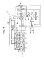
- FIG 4 shows another embodiment according to the present invention, in which the members or mechanisms equal with the ones shown in Figure 1 are designated by the same reference numerals as used in Figure 1.
- a so-called mechanical-type supercharger which is mechanically driven by a crankshaft of engine. That is, a Roots-type supercharger 41 is disposed in a common intake passage 13, and the supercharger 41 is connected to the crankshaft of engine 1 by means of an electromagnetic clutch 42.
- a throttle valve 43 is disposed on the upstream side of the supercharger 41 in the common intake passage 13.
- the common intake passage 13 On the downstream side of the throttle valve 43, the common intake passage 13 has a by-path passage 44 and a relief passage 45 arranged in parallel so as to be able to bypass the supercharger 41.
- the by-path passage 44 is provided with an on-off valve 46
- the relief passage 45 is provided with an on-off valve 47.
- the on-off valve 46, 47 and an on-off valve 23 disposed in a communicating passage portion 22 are adapted to be opened or closed by electromagnetic actuators 49, 50 and 48 respectively. Further, there is provided a control unit U, into which a signal from a supercharging pressure sensor 51 for sensing super charging pressure as well as a signal from an engine speed sensor 38, is inputted.
- the clutch 42 is operatively connected to drive the supercharger 41.
- the on-off valve 23 as well as the on-off valve 46 is kept in its closed position so that a surge tank 12 defines a pressure reflecting portion to form a relatively long resonance air column. Further, as easily understood, the on-off valve 46 is kept in its closed position.
- the clutch 42 is released to disengage with the supercharger 41 so that supercharger 41 is not driven, and the on-off valve 23 is opened.
- This allows the maximum supercharging pressure to shift to low level (actually, supercharging effect by the supercharger 41 is not provided) and the resonance air column to change into short length.
- the on-off valve 46 is forced to be opened.
- the on-off valve 47 located in the relief passage 45 is opened in the case where, the supercharging pressure is extraordinarily increased for any reasons during operation of the supercharger 41.
- the on-off valve 47 may be used to shift the supercharging pressure during operation of the supercharger 41 in such a manner as the aforementioned embodiment shown in Figure 1, wherein the on-off valve 23 be operated to be opened or closed synchronously with the shift of the supercharging pressure by the on-off valve 47.
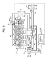
- Figure 5 shows still another embodiment in accordance with the present invention, in which the members or mechanisms corresponding to the ones shown in Figure 1 are designated by the same reference numerals as used therein.
- valve timing control mechanism 60 which comprises a cam shaft assembly 61 for driving intake valves (not shown) to open and close intake ports 2, a sleeve 60a generally H-like shaped in its section and incorporated into the cam shaft assembly 61, and a shift lever 60b being adapted to be controlled by a control unit U.
- the cam shaft assembly 61 is divided into two protions 61a and 61b, with one being cam shaft associated with cams for driving intake valves, the other being a portion connected with a pulley 62 which is driven in rotation by a crankshaft (not shown) by means of a timing belt (not shown).
- the portions 61a, 61b is respectively formed at their opposite end portion with helical splines 63a, 63b, which are oriented in opposite directions, and internal peripheral portions of two flanges 60a1 and 60a2 of the sleeve 60a respectively engages with the helical splines 63a, 63b.
- the control unit U inputs control signals into the shift lever 60b.
- relative phase angle between the portions 61a and 61b of the cam shaft assembly 61 that is, relative phase angle between the cam shaft and the crankshaft (not shown) is controlled by the sleeve 60 so that the intake valves are opened and closed in accordance with valve timing shown by a solid line in Figure 6 when the engine speed resides in a low speed range less than a predetermined engine speed, that is, the intake valves are closed at relatively early timing in the low engine speed range. Therefore, the charging efficiency is enhanced in the low engine speed range and thus, the torque of engine varies substantially along a predetermined torgue curve such like the torque corve X2 shown in Figure 2(b).
- control unit U senses on the basis of the signals inputted from an engine speed sensor 38 that the engine speed is increased up to the predetermined engine speed, the control unit U outputs a control signal into the shift lever 60b and permits the shift lever 60b to move the sleeve 60 axially.
- flanges 60a1 and 60a2 of the sleeve 60 allow the portions 61a and 61b of the cam shaft assembly 61 engaging therewith to rotate in opposite directions relatively to each other, so that the relative phase angle between the portions 61a and 61b, namely the one between the cam shaft and the crankshaft is changed and thereby, the timing for closing the intake valve is retarded as shown in a dotted line of Figure 6.
- the changing efficiency is enhanced in the high engine speed range, and the engine torque varies substantially along a desired torque curve such like the torque curve Y1 shown in Figure 2(b).
- control unit U permits a three way control valve 34 to operate an actuator 31 to shift the maximum permissible supercharging pressure to relatively low pressure.
- valve timing control mechanism 60 displaces the valve timing for closing the intake valve to change the condition of intake air and at the same time, the waste gate valve 26 is opened or closed to shift the maximum supercharging pressure, high charging efficiency of intake air can be ensured over a wide range of the engine speeds and knocking of the engine can be prevented.
- the lifting stroke may be changed to increase or decrease a period of opening time of the intake valve so as to change only the valve closing timing.
- the maximum supercharging pressure are set into two different pressures and the maximam pressure is stepwisely changed to either of them, but the maximum pressure may be set into three or more than three different pressurs which can respectively apply properly to the limiting lines shown in Fugure 3, and further, the length of resonance air column for obtaining the resonance effect may be changed over to three or more than three lengths
- the manner for controlling the maximum supercharging pressure are described as to a manner wherein the waste gate valve adjust the exhaust air flow introduced into the turbine of turbine-type supercharger, and another manner wherein the connecting condition between the crank shaft of the engine and the compressor of the mechanical-type supercharger is changed (engaged or disengaged), but the other various manners for control the supercharging pressure as known in the art, for example, a manner wherein the relief passage relieves the supercharging pressure provided by the compressor of the mechanical-type supercharger can be adaptd in accordance with the present invention.
Landscapes
- Engineering & Computer Science (AREA)
- Chemical & Material Sciences (AREA)
- Combustion & Propulsion (AREA)
- Mechanical Engineering (AREA)
- General Engineering & Computer Science (AREA)
- Health & Medical Sciences (AREA)
- Biomedical Technology (AREA)
- Supercharger (AREA)
- Characterised By The Charging Evacuation (AREA)
Abstract
Description
- This invention relates to an intake system for an internal combustion engine with supercharger.
- In recent years, considerable types of the internal combustion engines tend to be provided with any types of superchargers to supercharge intake air.
- In these superchargers, their supercharging pressures to be imposed on the intake air are generally limited in enhancing the pressure by some limiting factors involved with the characteristics of the engines. Taking the upper limits of the supercharging pressure into consideration in relation to engine speeds, in a low engine speed range, the supercharging pressures are to be limited for preventing knocking of engine, in a middle engine speed range, the supercharging pressures are to be limited for ensuring appropriate combustion pressures thereof, and in a high engine speed range, the supercharging pressures are to be limited for ensuring appropriate heat loads thereof. In these permissible supercharging pressures thus defined by these limiting factors, the permissible supercharging pressures depending on heat load of the engine is, in general, in the lowest level. Therefore, in the conventional engines, the maximum supercharging pressures have been substantially selected on the basis of the permissible supercharging pressure depending on the heat loads of the engines.
- In the internal combustion engines with superchargers as set forth above, it has been proposed that intake systems of the engines are arranged to supercharge the intake air further with so-called kinetic supercharging effects of intake air (for example, Japanese Utility-Model Laid-Open Publication No.62-49625). The kinetic effect is intended to improve the volumetric efficiency of cylinders of engine so as to enhance the torque of the engine, and includes an inertia effect of intake air and a resonance effect of intake air .
- Since preferred nature of the kinetic effect can be obtained in syncronism with a certain engine speed, in the intake system to take the kinetic effect, it has been proposed that there is provided a means for allowing the intake system to correspond to different engine speeds, thereby taking the advantageous kinetic effect in a wide range of the engine speeds.
- For example, the U.S. Patent 4,829,941 issued on May 16, 1989 to the same assignee as the present application discloses one type of intake system having means for changing over the length of the resonance air column in the intake system on the basis of the engine speeds to obtain the advantageous resonance effect of intake air over a wide range of engine speeds, and further, the U.S. Patent 4,617,897 issued on October 21, 1986 to the assignee as the present application discloses another type of intake system which is adapted to change the length of and the cross-sectional area of the intake passage for obtaining a preferred inertia effect of intake air over a wide range of engine speeds, and furthermore, the U.S. Patent 4,651,684 issued on May 24, 1987 to the same assignee as the present application discloses still another type of intake system in which the valve timing of intake valve is changed so as to vary the opening time thereof according to the operating condition of the engine whereby the volumetric efficiency is improved.
- Now, in the conventional engines with superchargers as previously mentioned, since the maximum value of the supercharging pressure provided by the supercharger has been settled on the basis of the limiting factor depending on the heat load of the engine, the engine can afford to enhance the supercharging pressures in the low and middle engine speed ranges. Therefore, it is taken into consideration that the maximum supercharging pressure is shifted in accordance with a parameter defined by engine speeds, that is, when, in simplification, the engine speed range is supposed to be divided into a relatively low range and a relatively high range, the maximum supercharging pressure is set into a high value in the low engine speed range and the maximum supercharging pressure is set into a low value in the high engine speed range, thereby changing over the maximum supercharging pressure between low and high value in accordance with the engine speeds.
- However, in such an arrangement, at the time when the maximum supercharging pressure is shifted, there is generated a great fluctuation in engine torque, that is, a torque shock and therefore, the approach to this problem has been required.
- Accordingly, it is an object of the present invention to provide an internal combustion engine with supercharger which can avoid the torque shock generated at the time when the maximum supercharging pressure of the supercharger is shifted.
- In accordance with the present invention, there is provided an
- An intake system for an internal combustion engine with supercharger comprising;
passage means for introducing intake air into each of cylinders of said engine, having first intake passages each of which is individually connected with each of said cylinders and a second intake passage which is in communication with said first intake passages;
supercharging means having a compressor which is disposed in said second intake passage for supercharging the intake air;
control means for varying supercharging pressure by said supercharger according to operating conditions of said engine;
varying means for changing characteristic of kinetic effect of the intake air so that a desired kinetic effect can be obtained in accordance with the operating conditions;
synchronizing means for allowing a timing or timings for varying the characteristics of the kinetic effect by said varying means to synchronize with a timing or timings for varying supercharging pressure by said control means. - In accordance with the present invention, reduction in torque generated at the time when the supercharging pressure is shifted, can be compensated by enhancement in the torque generated at the time when characteristics of kinetic effect of intake air vary. Thus, in an internal combustion engine with supercharger, an improved intake system which accomodates advantageously to both the functions of the supercharger and the kinetic effect of intake air can be obtained. In other words, the torque curve of the engine can be improved as a whole so that it represents smooth torque curve without generating greate fluctuation of the torque, namely torque shock upon the shift of the supercharging pressure.
- These and other objects and features of the invention will be more understood with reference to the following detailed description of illustrative embodiments of the invention, taken in connection with the accompanying drawings in which:
- Figure 1 is a schematic plan view illustrating diagramatically an internal combustion engine provided with an intake system in accordance with an embodiment of the present invention.
- Figure 2 is a graphical representation showing the characteristics in operation of the engine shown in Figure 1.
- Figure 3 is a graphical representation showing relationships among the limiting factors, maximum supercharging pressures and engine speeds for shifting the maximum supercharging pressure.
- Figure 4 is a schematic plan view illustrating diagramatically an internal combustion engine provided with an intake system in accordance with another embodiment of the present invention.
- Figure 5 is a schematic plan view illustrating diagramatically an internal combustion engine provided with an intake system in accordance with still another embodiment of the present invention.
- Figure 6 is a graphical representation showing a change in the valve timing of the engine shown in Figure 5 in relation to the crank angles.
- Referring to Figure 1, an Otto-cycle four-
cylinder engine 1 is shown therein, each of the cylinders C1-C4 of theengine 1 being provided with anintake port 2 andexhaust port 3. Theintake ports 2 and theexhaust ports 3 are opened or closed in timed relations in synchronism with rotation of a crankshaft (not shown) of the engine by intake valves and exhaust valves (not shown), as well-known in the art. - An intake passage 11 for introducing intake air into the cylinders C1-C4 has in its way a
surge tank 12, which functions as a first pressure reflecting portion. Thesurge tank 12 is adapted to be supplied with the intake air through onecommon intake passage 13, which is provided with anair cleaner 14, an air-flow meter 15, acompressor 16a of a turbo-type supercharger (referred to as a "turbo-charger" hereinafter), and aninter cooler 17, one after another from an upstream side. - The intake passage 11 is divided into two
branch intake passages surge tank 12, and thebranch intake passages throttle valves throttle valve 19A, thebranch intake passage 18A individually communicates through discrete intake passages 20-1, 20-4 with each of theintake ports 2 of the first and forth cylinders C1, C4 which do not fire successively. Further, on a downstream side of thethrottle valve 19B, the branch intake passae 18B individually communicates through discrete intake passages 20-2, 20-3 with each of theintake ports 2 of the second and third cylinders C2, C3 which do not fire successively. Each of the discrete intake passages 20-1∼20-4 is provided with afuel injection valve 21. - The
branch intake passages surge tank 12, in communication with each other through a communicatingpassage 22 which functions as a second pressure reflecting portion, and thecommunicating passages 22 is provided with an on-offvalve 23 which can open and close the communicatingpassage 22. The distance between each of theintake ports 2 and the surge tank 12 (the first pressure reflecting portion) taken along the discrete passage and the branch passage, is set to be larger than the distance between each of theintake port 2 and the communicating passage 22 (the second pressure reflecting portion) taken along the discrete and branch passages. Therefore, when the on-offvalve 23 is closed, thesurge tank 12 comes to act as the pressure reflecting portion and the resonance air column is set into relatively long length, whereby the length of the resonance air column can correspond to relatively low engine speed range for obtaining the proper kinetic effect of intake air therein. On the other hand, when said on-offvalve 23 is opened, the communicating portion comes to act as thepressure reflecting portion 22 and the resonance air column is set into relatively short length, whereby the length of the resonance air column can correspond to relatively high engine speed range for obtaining the proper kinetic effect of intake air therein. Variations in the volumetic efficiency involved by such opening and closing of the on-offvalve 23, are shown in Figure 2(a), in which the curve X1 represents the variation in a state where the on-offvalve 23 is closed and the curve Y1 indicates the variation in a state where the on-offvalve 23 is opened. - Further, an
exhaust passage 24 in communication with theexhaust ports 3 is joined into a single passage, and on the downstream side of the joined portion, aturbine 16b of said turbo-charger 16 is located. Theturbine 16b is connected to saidcompressor 16a by means of ashaft 16c, so that the rotation of theturbine 16b by the energy of the exhaust air allows thecompressor 16a to rotate to effect supercharging of the intake air. Still further, theexhaust passage 24 is provided with a by-path passage 25 bypassing theturbine 16b, in which a waste gate valve 26b is disposed for defining the maximum pressure of the supercharged intake air. - The pressure for opening the waste gate valve 26 is adjusted by an
actuator 31 reciprocating in responses to fluid-pressure. Theactuator 31 has a first diaphragm 31b which defines a first chamber 31a and a second diaphragm 31d which defines asecond chamber 31c, and the first and second diaphragms 31b, 31d are connected to the waste gate valve 26 by means of ashaft 32. The waste gate valve 26 is normally energized by a return spring 31e so as to close the by-path passage 25. - The first chamber 31a normally communicates by way of a
signal line 33 with thecommon intake passage 13 on the downstream side of thecompressor 16a. Thesecond chamber 31c is connected to thesignal line 33 by way of asignal line 35 and a solenoid operated threeway control valve 34 connected with thesignal line 35. Thecontrol valve 34 has a first position in which thesignal line 35 communicates with thesignal line 33, and a second position in which asignal line 35 is released to the atmosphere. Therefore, when thecontrol valve 34 takes the second position, thesecond chamber 31c is released to the atmosphere and the supercharging pressure provided by the turbo-charger 16 acts on only the first chamber 31a, so that the waste gate valve 26 is to be opened when the supercharging pressure reaches the first maximum supercharging pressure PM1 which is settled to be relatively high value. On the other hand, when thecontrol valve 34 takes its first position, the supercharging pressure provided by the turbo-charger 16 acts on both the first andsecond chambers 31a, 31c, so that the waste gate valve 26 is to be opened when the supercharging pressure reaches the second maximum pressure PM2 which is settled to be relatively low value. These different maximum pressures PM1 and PM2 are indicated in Figure 2(c). - Further, the on-off
valve 23 is opened and closed by anactuator 36 reciprocating in responses to fluid-pressure. Theactuator 36 has adiaphragm 36b which defines achamber 36a, and thediaphragm 36b is connected to the on-offvalve 23. Thechamber 36a is in communication with asignal line 37 which branches from thesignal line 35 downstream thecontrol valve 34. Therefore, when the control valve takes the second position, thechamber 36a is released to the atmosphere so that the on-offvalve 23 is closed. On the other hand, when thecontrol valve 34 resides in the first position, the supercharging pressure acts on thechamber 36a so that the on-offvalve 23 is opened. Thus, the on-offvalve 23 is operated corresponding to a shift of the maximum supercharging pressures to vary the length of the resonance air column for obtaining desired kinetic effect of intake air, and the engine speed in which the maximum pressure is shifted and the on-off valve is operated, is referred to as a line E2 in Figure 2. - In order to change over the positions of the
control valve 34 on the basis of the engine speeds, there is provided a control unit U, and an engine speed signals is introduced into the control unit U from anengine speed sensor 38. The control unit U operates thecontrol valve 34 in such a manner as above described when the engine speed reaches the value E2. - In Figure 2b, torque curves of the engine are shown, which are provided by the aforementioned position control of the
control valve 34. The curve X2 of the torque curves represents the engine torque in the case where the maximum supercharging pressure is set into PM1 and the resonance air column is set into relatively long length, and the curve Y2 of the torque curves represents the engine torque in the case where the maximum supercharging pressure is set into PM2 and the resonance air column is set into relatively short length. The engine speed E2 is to be selected so as to correspond to the intersection of the curve X2 and the curve Y2, and value of E2 in conventional type of engines is generally seleced to, for example 2500rpm ∼ 3000rpm. Further, the torque curve Z represented in Figure 2(b) by a phantom line indicates the engine torque in the case where the maximum supercharging pressure would be constantly set to be PM2 and the resonance air column would be set into relatively long length in overall engine speed range. Still further, the engine speed E1 shown in Figure 2(d) indicates an engine speed selected in accordance with conventional manner such that the length of the resonance air column is changed over at the engine speed for obtaining the appropriate kinetic effect of intake air with the maximum supercharging pressure kept in constant value. - In Figure 3, there is shown how the aforementioned engine speed E2 and maximum supercharging pressure PM1, PM2 is selected in relation to limiting factors of the supercharging pressure for ensuring an appropriate operation of the engine. In Figure 3, a line α indicates a limiting line for preventing knocking of the engine, a line β indicates a limiting line for maintaining appropriate combustion pressure, and a line γ indicates a limiting line for ensuring appropriate heat load.
- It will be understood from the description as set forth above that, according to the present invention, when the maximum supercharging pressure is shifted in accordance with the engine speed ranges of the engine, the torque shock at the time of shifting the pressure can be prevented. Further, since the supercharging pressure can be enhanced in relatively low engine speed range, the advantageous torque in an Otto-cycle engine, can be ensured during operation thereof in the low engine speed range, and further in a diesel engine, the response thereof can be advantageously ensured particularly during quick accelerating.
- Figure 4 shows another embodiment according to the present invention, in which the members or mechanisms equal with the ones shown in Figure 1 are designated by the same reference numerals as used in Figure 1.
- In the present embodiment, there is provided a so-called mechanical-type supercharger which is mechanically driven by a crankshaft of engine. That is, a Roots-
type supercharger 41 is disposed in acommon intake passage 13, and thesupercharger 41 is connected to the crankshaft ofengine 1 by means of an electromagnetic clutch 42. Athrottle valve 43 is disposed on the upstream side of thesupercharger 41 in thecommon intake passage 13. On the downstream side of thethrottle valve 43, thecommon intake passage 13 has a by-path passage 44 and arelief passage 45 arranged in parallel so as to be able to bypass thesupercharger 41. The by-path passage 44 is provided with an on-offvalve 46, and therelief passage 45 is provided with an on-offvalve 47. The on-offvalve valve 23 disposed in a communicatingpassage portion 22 are adapted to be opened or closed byelectromagnetic actuators engine speed sensor 38, is inputted. - In the
engine 1 having the arrangement as above described, when the engine speeds is lower than a predetermined speed, that is, when the engine speeds reside in a range in which driving resistance of the supercharger is not extremely increased, the clutch 42 is operatively connected to drive thesupercharger 41. Simultaneously, the on-offvalve 23 as well as the on-offvalve 46 is kept in its closed position so that asurge tank 12 defines a pressure reflecting portion to form a relatively long resonance air column. Further, as easily understood, the on-offvalve 46 is kept in its closed position. - On the other hand, when the engine speed is increased to higher level than the predetermined speed, the clutch 42 is released to disengage with the
supercharger 41 so thatsupercharger 41 is not driven, and the on-offvalve 23 is opened. This allows the maximum supercharging pressure to shift to low level (actually, supercharging effect by thesupercharger 41 is not provided) and the resonance air column to change into short length. Further, as easily understood, while thesupercharger 41 is not operated, the on-offvalve 46 is forced to be opened. - As set forth above, since the length of the resonance air column to obtain an advantageous kinetic effect of intake air, is changed over in synchronism with the switching of the
supercharger 41 between operating state and unoperating state thereof, the torque shock generated in theengine 1 upon the switching therebetween can be prevented similarly to the aforementioned embodiment shown in Figure 1. - In addition, the on-off
valve 47 located in therelief passage 45 is opened in the case where, the supercharging pressure is extraordinarily increased for any reasons during operation of thesupercharger 41. Alternatively, the on-offvalve 47 may be used to shift the supercharging pressure during operation of thesupercharger 41 in such a manner as the aforementioned embodiment shown in Figure 1, wherein the on-offvalve 23 be operated to be opened or closed synchronously with the shift of the supercharging pressure by the on-offvalve 47. - Figure 5 shows still another embodiment in accordance with the present invention, in which the members or mechanisms corresponding to the ones shown in Figure 1 are designated by the same reference numerals as used therein.
- In an
internal combustion engine 1 according to the present embodiment, there is provided valvetiming control mechanism 60, which comprises a cam shaft assembly 61 for driving intake valves (not shown) to open andclose intake ports 2, asleeve 60a generally H-like shaped in its section and incorporated into the cam shaft assembly 61, and ashift lever 60b being adapted to be controlled by a control unit U. The cam shaft assembly 61 is divided into two protions 61a and 61b, with one being cam shaft associated with cams for driving intake valves, the other being a portion connected with apulley 62 which is driven in rotation by a crankshaft (not shown) by means of a timing belt (not shown). The portions 61a, 61b is respectively formed at their opposite end portion withhelical splines sleeve 60a respectively engages with thehelical splines shift lever 60b. - According to the
engine 1 having such an arrangement, relative phase angle between the portions 61a and 61b of the cam shaft assembly 61, that is, relative phase angle between the cam shaft and the crankshaft (not shown) is controlled by thesleeve 60 so that the intake valves are opened and closed in accordance with valve timing shown by a solid line in Figure 6 when the engine speed resides in a low speed range less than a predetermined engine speed, that is, the intake valves are closed at relatively early timing in the low engine speed range. Therefore, the charging efficiency is enhanced in the low engine speed range and thus, the torque of engine varies substantially along a predetermined torgue curve such like the torque corve X2 shown in Figure 2(b). - As the control unit U senses on the basis of the signals inputted from an
engine speed sensor 38 that the engine speed is increased up to the predetermined engine speed, the control unit U outputs a control signal into theshift lever 60b and permits theshift lever 60b to move thesleeve 60 axially. Since thehelical splines sleeve 60 allow the portions 61a and 61b of the cam shaft assembly 61 engaging therewith to rotate in opposite directions relatively to each other, so that the relative phase angle between the portions 61a and 61b, namely the one between the cam shaft and the crankshaft is changed and thereby, the timing for closing the intake valve is retarded as shown in a dotted line of Figure 6. Therefor, the changing efficiency is enhanced in the high engine speed range, and the engine torque varies substantially along a desired torque curve such like the torque curve Y1 shown in Figure 2(b). - At the time when the valve timing is displaced so as to retard the timing for closing the intake valve, the control unit U permits a three
way control valve 34 to operate anactuator 31 to shift the maximum permissible supercharging pressure to relatively low pressure. - As can be understood from the aforementioned matters, in the present embodiment, since the valve
timing control mechanism 60 displaces the valve timing for closing the intake valve to change the condition of intake air and at the same time, the waste gate valve 26 is opened or closed to shift the maximum supercharging pressure, high charging efficiency of intake air can be ensured over a wide range of the engine speeds and knocking of the engine can be prevented. - Further, although in this embodiment, the relative phase angle between the cam shaft and the crankshaft is changed, thereby the valve timing being displaced in parallelism to change the valve timing for closing the intake valve, the lifting stroke may be changed to increase or decrease a period of opening time of the intake valve so as to change only the valve closing timing.
- Still further, in the embodiments as set forth above, the maximum supercharging pressure are set into two different pressures and the maximam pressure is stepwisely changed to either of them, but the maximum pressure may be set into three or more than three different pressurs which can respectively apply properly to the limiting lines shown in
Fugure 3, and further, the length of resonance air column for obtaining the resonance effect may be changed over to three or more than three lengths - Also, the manner for controlling the maximum supercharging pressure are described as to a manner wherein the waste gate valve adjust the exhaust air flow introduced into the turbine of turbine-type supercharger, and another manner wherein the connecting condition between the crank shaft of the engine and the compressor of the mechanical-type supercharger is changed (engaged or disengaged), but the other various manners for control the supercharging pressure as known in the art, for example, a manner wherein the relief passage relieves the supercharging pressure provided by the compressor of the mechanical-type supercharger can be adaptd in accordance with the present invention.
- While the embodiments of present invention, as herein disclosed, constitute a preferred form, it is to be understood that other forms might be adopted.
Claims (16)
passage means for introducing intake air into each of cylinders of said engine, having first intake passages each of which is individually connected with each of said cylinders and a second intake passage which is in communication with said first intake passages;
supercharging means having a compressor which is disposed in said second intake passage for supercharging the intake air;
control means for varying supercharging pressure according to operating conditions of said engine;
varying means for changing characteristic of kinetic supercharging effect of the intake air so that a desired kinetic supercharging effect can be obtained in accordance with the operating conditions;
synchronizing means for allowing a timing or timings for varying the characteristics of the kinetic effect by said varying means to synchronize with a timing or timings for varying supercharging pressure by said control means.
passage means for introducing intake air into each of cylinders of said engine, having first intake passages each of which is individually connected with each of said cylinders and a second intake passage which is in communication with said first intake passages;
supercharging means having a compressor which is disposed in said second intake passage for supercharging the intake air;
control means for varying supercharging pressure according to operating conditions of said engine;
varying means for changing characteristic of kinetic supercharging effect of the intake air so that a desired kinetic supercharging effect can be obtained in accordance with the operating conditions;
wherein said control means controls the maximum permissible supercharging pressure of intake air so that, when engine speeds reside in a relatively high engine speed range over a predetermined engine speed, the maximum permissible supercharging pressure is set into relatively lower pressure than the maximum permissible supercharging pressure being set when the engine speed resides in relatively low engine speed range less than the predetermined engine speed, and
said second intake passage includes a common intake passage being provided with said compressor and two branch intake passages divided from a downstream portion of said common intake passages, one of said branch intake passages communicating with predetermined first intake passage or passages, the other of said branch passages communicating with the other first passage or passages, said varying means including a communicating passage portion communicating with each of the said branch intake passages and valve means for permitting one of said branch intake passages to communicate with the other thereof,
said valve means bringing one of said branch intake passages into comunication with the other thereof when the engine speeds reside in the high engine speed range whilst closing the communication between one of said branch passages and the other thereof when the engine speeds reside in the low engine speed range.
passage means for introducing intake air into each of cylinders of said engine, having first intake passages each of which is individually connected with each of said cylinders and a second intake passage which is in communication with said first intake passages;
supercharging means having a compressor which is disposed in said second intake passage for supercharging the intake air;
control means for varying supercharging pressure according to operating conditions of said engine;
varying means for changing characteristic of kinetic supercharging effect of the intake air so that a desired kinetic supercharging effect can be obtained in accordance with the operating conditions;
wherein said control means controls the maximum permissible supercharging pressure of intake air so that, when engine speeds reside in a relatively high engine speed range over a predetermined engine speed, the maximum permissible supercharging pressure is set into relatively lower pressure than the maximum permissible supercharging pressure being set when the engine speed resides in relatively low engine speed range less than the predetermined engine speed,
said varying means having means for changing closing timing of intake valves disposed in said cylinders,
the closing timing being selected to be a first closing timing in the low engine speed range and selected to be a second timing in the high engine speed range, the second timing being decided to be later timing than the first timing.
Applications Claiming Priority (2)
| Application Number | Priority Date | Filing Date | Title |
|---|---|---|---|
| JP274120/88 | 1988-10-29 | ||
| JP63274120A JPH0656106B2 (en) | 1988-10-29 | 1988-10-29 | Intake device for supercharged engine |
Publications (3)
| Publication Number | Publication Date |
|---|---|
| EP0367150A2 true EP0367150A2 (en) | 1990-05-09 |
| EP0367150A3 EP0367150A3 (en) | 1990-07-25 |
| EP0367150B1 EP0367150B1 (en) | 1994-12-28 |
Family
ID=17537297
Family Applications (1)
| Application Number | Title | Priority Date | Filing Date |
|---|---|---|---|
| EP89120020A Expired - Lifetime EP0367150B1 (en) | 1988-10-29 | 1989-10-27 | Intake system for an internal combustion engine with supercharger |
Country Status (4)
| Country | Link |
|---|---|
| US (1) | US5090202A (en) |
| EP (1) | EP0367150B1 (en) |
| JP (1) | JPH0656106B2 (en) |
| DE (1) | DE68920276T2 (en) |
Cited By (2)
| Publication number | Priority date | Publication date | Assignee | Title |
|---|---|---|---|---|
| EP0497457A1 (en) * | 1991-01-31 | 1992-08-05 | Jaguar Cars Limited | Air induction system for an internal combustion engine |
| EP2503124A1 (en) * | 2011-03-23 | 2012-09-26 | MAHLE International GmbH | Combustion engine, fresh air system and associated operating method |
Families Citing this family (33)
| Publication number | Priority date | Publication date | Assignee | Title |
|---|---|---|---|---|
| JP3067783B2 (en) * | 1990-05-18 | 2000-07-24 | マツダ株式会社 | Vehicle engine output control device |
| US5197433A (en) * | 1992-04-30 | 1993-03-30 | Dykstra Gregory J | Anticipatory intake manifold tuning valve control |
| JP3422033B2 (en) * | 1992-09-28 | 2003-06-30 | マツダ株式会社 | Intake device for engine with mechanical supercharger |
| US5386698A (en) * | 1993-12-13 | 1995-02-07 | Cummins Engine Company, Inc. | Control system and method for governing turbocharged internal combustion engines |
| SE504646C2 (en) * | 1995-07-11 | 1997-03-24 | Volvo Ab | Intake system for multi-cylinder internal combustion engines |
| US5755101A (en) * | 1996-03-28 | 1998-05-26 | Cummins Engine Company, Inc. | Electronic turbocharger wastegate controller |
| US5873248A (en) * | 1996-06-21 | 1999-02-23 | Caterpillar Inc. | Turbocharger control system |
| US7281527B1 (en) | 1996-07-17 | 2007-10-16 | Bryant Clyde C | Internal combustion engine and working cycle |
| US7222614B2 (en) * | 1996-07-17 | 2007-05-29 | Bryant Clyde C | Internal combustion engine and working cycle |
| US8215292B2 (en) * | 1996-07-17 | 2012-07-10 | Bryant Clyde C | Internal combustion engine and working cycle |
| US6561145B1 (en) * | 2000-11-21 | 2003-05-13 | Ford Global Technologies, Llc | Torque control method and system in an engine with a fully variable intake valve |
| US7178492B2 (en) | 2002-05-14 | 2007-02-20 | Caterpillar Inc | Air and fuel supply system for combustion engine |
| US6688280B2 (en) * | 2002-05-14 | 2004-02-10 | Caterpillar Inc | Air and fuel supply system for combustion engine |
| US7201121B2 (en) * | 2002-02-04 | 2007-04-10 | Caterpillar Inc | Combustion engine including fluidically-driven engine valve actuator |
| US20050235950A1 (en) * | 2002-05-14 | 2005-10-27 | Weber James R | Air and fuel supply system for combustion engine |
| US20050247284A1 (en) * | 2002-05-14 | 2005-11-10 | Weber James R | Air and fuel supply system for combustion engine operating at optimum engine speed |
| US7191743B2 (en) * | 2002-05-14 | 2007-03-20 | Caterpillar Inc | Air and fuel supply system for a combustion engine |
| US20050229900A1 (en) * | 2002-05-14 | 2005-10-20 | Caterpillar Inc. | Combustion engine including exhaust purification with on-board ammonia production |
| US7252054B2 (en) * | 2002-05-14 | 2007-08-07 | Caterpillar Inc | Combustion engine including cam phase-shifting |
| US20050235951A1 (en) * | 2002-05-14 | 2005-10-27 | Weber James R | Air and fuel supply system for combustion engine operating in HCCI mode |
| US20050235953A1 (en) * | 2002-05-14 | 2005-10-27 | Weber James R | Combustion engine including engine valve actuation system |
| CA2487849A1 (en) | 2002-07-18 | 2004-01-29 | Cytos Biotechnology Ag | Hapten-carrier conjugates comprising virus like particles and uses thereof |
| EP2338510A1 (en) | 2002-07-19 | 2011-06-29 | Novartis Pharma AG | Vaccine compositions containing amyloid beta1-6 antigen arrays |
| US20040177837A1 (en) * | 2003-03-11 | 2004-09-16 | Bryant Clyde C. | Cold air super-charged internal combustion engine, working cycle & method |
| WO2005019619A1 (en) * | 2003-08-18 | 2005-03-03 | Bryant, Clyde, C. | Improved internal combustion engine and working cycle |
| DE102004047180B4 (en) * | 2004-09-29 | 2014-07-17 | Robert Bosch Gmbh | Charging device with load control on internal combustion engines |
| DE102004061613A1 (en) * | 2004-12-17 | 2006-07-06 | Volkswagen Ag | Method for operating an internal combustion engine with charge air charging and internal combustion engine |
| US7748366B2 (en) * | 2005-12-08 | 2010-07-06 | Ford Global Technologies, Llc | Electronic throttle control supercharging |
| US7353699B2 (en) * | 2005-12-08 | 2008-04-08 | Ford Global Technologies, Llc | Electronic throttle control supercharging |
| CN101082318B (en) | 2006-05-31 | 2011-09-21 | 卡特彼勒公司 | Turbo-charger control system |
| WO2010113300A1 (en) * | 2009-04-01 | 2010-10-07 | トヨタ自動車株式会社 | Control device for vehicle |
| US8661814B2 (en) * | 2011-05-16 | 2014-03-04 | Ford Global Technologies, Llc | Method and system for controlling a turbocharger compressor bypass |
| KR20200069932A (en) * | 2018-12-07 | 2020-06-17 | 현대자동차주식회사 | Intake manifold |
Family Cites Families (17)
| Publication number | Priority date | Publication date | Assignee | Title |
|---|---|---|---|---|
| JPS5741425A (en) * | 1980-08-22 | 1982-03-08 | Honda Motor Co Ltd | Controller of engine with supercharger |
| SE458290B (en) * | 1981-02-19 | 1989-03-13 | Volvo Ab | DEVICE FOR CONTROL OF CHARGING PRESSURE IN A TURBOLED FORMING ENGINE |
| JPS5827812A (en) * | 1981-08-10 | 1983-02-18 | Daihatsu Motor Co Ltd | Supercharger of internal-combustion engine |
| JPS5918226A (en) * | 1982-07-22 | 1984-01-30 | Aisin Seiki Co Ltd | Controlling method of supercharger for automobile engine |
| JPS5946310A (en) * | 1982-09-10 | 1984-03-15 | Mazda Motor Corp | Valve timing control device of engine |
| JPS605772A (en) * | 1983-06-20 | 1985-01-12 | Seiko Epson Corp | Dc stabilized power source circuit |
| JPS6075721A (en) * | 1983-09-30 | 1985-04-30 | Hino Motors Ltd | Control device for internal-combustion engine with supercharger |
| JPS60104717A (en) * | 1983-11-11 | 1985-06-10 | Nissan Motor Co Ltd | Internal-combustion engine equipped with supercharger |
| US4617897A (en) * | 1984-01-23 | 1986-10-21 | Mazda Motor Corporation | Intake system for internal combustion engines |
| JPS611836A (en) * | 1984-06-11 | 1986-01-07 | Mazda Motor Corp | Suction apparatus for engine |
| JPS6166824A (en) * | 1984-09-10 | 1986-04-05 | Mazda Motor Corp | Valve timing control device of engine |
| JPS61200331A (en) * | 1985-03-01 | 1986-09-04 | Nissan Motor Co Ltd | Multi-turbocharger |
| JPS6249625A (en) * | 1985-08-28 | 1987-03-04 | Mitsubishi Electric Corp | Manufacture of semiconductor device |
| JPS63111227A (en) * | 1986-10-30 | 1988-05-16 | Mazda Motor Corp | Suction device for engine |
| JP2543537B2 (en) * | 1986-10-30 | 1996-10-16 | マツダ株式会社 | Intake device for V-type multi-cylinder engine |
| JP2517584B2 (en) * | 1987-03-24 | 1996-07-24 | マツダ株式会社 | Engine mechanical supercharger |
| JP2863927B2 (en) * | 1988-03-15 | 1999-03-03 | マツダ株式会社 | Engine intake system |
-
1988
- 1988-10-29 JP JP63274120A patent/JPH0656106B2/en not_active Expired - Fee Related
-
1989
- 1989-10-27 US US07/427,480 patent/US5090202A/en not_active Expired - Fee Related
- 1989-10-27 EP EP89120020A patent/EP0367150B1/en not_active Expired - Lifetime
- 1989-10-27 DE DE68920276T patent/DE68920276T2/en not_active Expired - Fee Related
Cited By (3)
| Publication number | Priority date | Publication date | Assignee | Title |
|---|---|---|---|---|
| EP0497457A1 (en) * | 1991-01-31 | 1992-08-05 | Jaguar Cars Limited | Air induction system for an internal combustion engine |
| US5190007A (en) * | 1991-01-31 | 1993-03-02 | Jaguar Cars Limited | Air induction system for an internal combustion engine |
| EP2503124A1 (en) * | 2011-03-23 | 2012-09-26 | MAHLE International GmbH | Combustion engine, fresh air system and associated operating method |
Also Published As
| Publication number | Publication date |
|---|---|
| JPH02119624A (en) | 1990-05-07 |
| DE68920276T2 (en) | 1995-05-18 |
| EP0367150B1 (en) | 1994-12-28 |
| EP0367150A3 (en) | 1990-07-25 |
| DE68920276D1 (en) | 1995-02-09 |
| JPH0656106B2 (en) | 1994-07-27 |
| US5090202A (en) | 1992-02-25 |
Similar Documents
| Publication | Publication Date | Title |
|---|---|---|
| EP0367150B1 (en) | Intake system for an internal combustion engine with supercharger | |
| US5105784A (en) | Rotary valve and system for duration and phase control | |
| US5421308A (en) | Control system for engine with mechanical supercharger | |
| US7644586B2 (en) | Control of supercharged engine | |
| US6595183B1 (en) | Internal combustion engine | |
| US5396874A (en) | Controller for supercharged engine | |
| US4930315A (en) | Turbo-charger engine system | |
| US5138839A (en) | Control system for internal combustion engine with turbo supercharger | |
| US4426985A (en) | Supercharged internal combustion engine | |
| US4461151A (en) | Internal combustion engine | |
| EP0413317B1 (en) | Exhaust control valve system for parallel multi-cylinder two-cycle engine | |
| WO2008032109A1 (en) | Engine and method for operating an engine | |
| US20100191442A1 (en) | Internal combustion engine cycle | |
| US4996966A (en) | Supercharged engine | |
| JP3551435B2 (en) | Engine with turbocharger | |
| JP3783765B2 (en) | EGR device for turbocharged engine | |
| EP1242720B1 (en) | Four-stroke internal combustion engine with variable cam timing | |
| GB2223800A (en) | I.C. engine valve gear | |
| JP3184247B2 (en) | Intake device for engine with mechanical supercharger | |
| EP0262769A2 (en) | Internal combustion engine having two intake valves per cylinder | |
| JPH02119641A (en) | Valve system of engine | |
| JPH0621579B2 (en) | Variable valve timing engine control method | |
| JP2515812B2 (en) | Control device for engine with supercharger | |
| JPH059610B2 (en) | ||
| JPH0544528B2 (en) |
Legal Events
| Date | Code | Title | Description |
|---|---|---|---|
| PUAI | Public reference made under article 153(3) epc to a published international application that has entered the european phase |
Free format text: ORIGINAL CODE: 0009012 |
|
| AK | Designated contracting states |
Kind code of ref document: A2 Designated state(s): DE FR GB |
|
| PUAL | Search report despatched |
Free format text: ORIGINAL CODE: 0009013 |
|
| RHK1 | Main classification (correction) |
Ipc: F02B 33/44 |
|
| AK | Designated contracting states |
Kind code of ref document: A3 Designated state(s): DE FR GB |
|
| 17P | Request for examination filed |
Effective date: 19901115 |
|
| 17Q | First examination report despatched |
Effective date: 19920114 |
|
| GRAA | (expected) grant |
Free format text: ORIGINAL CODE: 0009210 |
|
| AK | Designated contracting states |
Kind code of ref document: B1 Designated state(s): DE FR GB |
|
| REF | Corresponds to: |
Ref document number: 68920276 Country of ref document: DE Date of ref document: 19950209 |
|
| ET | Fr: translation filed | ||
| PLBE | No opposition filed within time limit |
Free format text: ORIGINAL CODE: 0009261 |
|
| STAA | Information on the status of an ep patent application or granted ep patent |
Free format text: STATUS: NO OPPOSITION FILED WITHIN TIME LIMIT |
|
| 26N | No opposition filed | ||
| PGFP | Annual fee paid to national office [announced via postgrant information from national office to epo] |
Ref country code: FR Payment date: 20011010 Year of fee payment: 13 |
|
| PGFP | Annual fee paid to national office [announced via postgrant information from national office to epo] |
Ref country code: GB Payment date: 20011031 Year of fee payment: 13 |
|
| PGFP | Annual fee paid to national office [announced via postgrant information from national office to epo] |
Ref country code: DE Payment date: 20011112 Year of fee payment: 13 |
|
| REG | Reference to a national code |
Ref country code: GB Ref legal event code: IF02 |
|
| PG25 | Lapsed in a contracting state [announced via postgrant information from national office to epo] |
Ref country code: GB Free format text: LAPSE BECAUSE OF NON-PAYMENT OF DUE FEES Effective date: 20021027 |
|
| PG25 | Lapsed in a contracting state [announced via postgrant information from national office to epo] |
Ref country code: DE Free format text: LAPSE BECAUSE OF NON-PAYMENT OF DUE FEES Effective date: 20030501 |
|
| GBPC | Gb: european patent ceased through non-payment of renewal fee | ||
| PG25 | Lapsed in a contracting state [announced via postgrant information from national office to epo] |
Ref country code: FR Free format text: LAPSE BECAUSE OF NON-PAYMENT OF DUE FEES Effective date: 20030630 |
|
| REG | Reference to a national code |
Ref country code: FR Ref legal event code: ST |