EP0367154A2 - Optimalisation de l'organisation de plusieurs éléments discrets - Google Patents
Optimalisation de l'organisation de plusieurs éléments discrets Download PDFInfo
- Publication number
- EP0367154A2 EP0367154A2 EP89120029A EP89120029A EP0367154A2 EP 0367154 A2 EP0367154 A2 EP 0367154A2 EP 89120029 A EP89120029 A EP 89120029A EP 89120029 A EP89120029 A EP 89120029A EP 0367154 A2 EP0367154 A2 EP 0367154A2
- Authority
- EP
- European Patent Office
- Prior art keywords
- elements
- value
- improvement
- objective function
- organization
- Prior art date
- Legal status (The legal status is an assumption and is not a legal conclusion. Google has not performed a legal analysis and makes no representation as to the accuracy of the status listed.)
- Granted
Links
Images






Classifications
-
- G—PHYSICS
- G06—COMPUTING OR CALCULATING; COUNTING
- G06F—ELECTRIC DIGITAL DATA PROCESSING
- G06F17/00—Digital computing or data processing equipment or methods, specially adapted for specific functions
-
- G—PHYSICS
- G06—COMPUTING OR CALCULATING; COUNTING
- G06Q—INFORMATION AND COMMUNICATION TECHNOLOGY [ICT] SPECIALLY ADAPTED FOR ADMINISTRATIVE, COMMERCIAL, FINANCIAL, MANAGERIAL OR SUPERVISORY PURPOSES; SYSTEMS OR METHODS SPECIALLY ADAPTED FOR ADMINISTRATIVE, COMMERCIAL, FINANCIAL, MANAGERIAL OR SUPERVISORY PURPOSES, NOT OTHERWISE PROVIDED FOR
- G06Q10/00—Administration; Management
- G06Q10/04—Forecasting or optimisation specially adapted for administrative or management purposes, e.g. linear programming or "cutting stock problem"
- G06Q10/047—Optimisation of routes or paths, e.g. travelling salesman problem
-
- G—PHYSICS
- G06—COMPUTING OR CALCULATING; COUNTING
- G06F—ELECTRIC DIGITAL DATA PROCESSING
- G06F30/00—Computer-aided design [CAD]
- G06F30/30—Circuit design
- G06F30/39—Circuit design at the physical level
- G06F30/392—Floor-planning or layout, e.g. partitioning or placement
Definitions
- This invention relates to a method and an apparatus for optimizing an organization of many discrete elements.
- Such an optimization of an organization of many discrete elements is necessary for the resolution of a cell assignment problem of a logical functional element mask (a cell element mask) in circuit mask layout of the standard-cell type or the gate-array type in the fabrication of a semiconductor device.
- a logical functional element mask a cell element mask
- an optimal assignment organization of a group of cell elements which satisfies an objective specification of LSI mask layout must be determined by using previously-prepared cell element groups composing a device to be formed on a semiconductor substrate, and by using logical net information representing the relation among the cell element groups.
- the objective specification of LSI mask layout means the determination of an cell element assignment organization which satisfies a plurality of conditions such as a minimization of the chip area size and a minimization of the estimated total wire length.
- a cell assignment problem in the standard-cell layout method or the gate-array layout method can not be easily resolved by examining all possible organizations to determine an optimal organization. Accordingly, an inexpensive and quick optimization of an organization has been desired in such a large number of discrete elements.
- United States Patent 3,654,615 relates to an element placement system in which a first element organization is modified into a second element organization; an objective function value representing the degree of the nearness of the second element organization to an objective specification is calculated; the objective function value is examined to determine whether or not an improvement is present; and such processes are repeated to find an element organization well matching to the objective specification.
- the element organization which is obtained through the repetition of a local change is far from an objective specification than the element organization which is obtained through the repetition of a global change is.
- United States Patent 3,654,615 since the improvement of an element organization is performed through only local changes, a finally-obtained element organization tends to be inferior to a final element organization obtained through global changes.
- United States Patent 4,495,559 relates to an optimization of an organization of discrete elements which considers a global element organization.
- United States Patent 4,495,559 an attention is paid to a natural phenomenon of annealing in which an organization of atoms and molecules of a substance gradually changes from a disordered state to an energy-lowest ground state during the gradually cooling (annealing) of the substance from a high temperature state to a low temperature state.
- United States Patent 4,495,559 uses the fact that a computer simulation can reproduces such a phenomenon.
- a temperature parameter and a cooling schedule parameter greatly affect a finally-obtained element organization in the method of simulated annealing.
- the cooling schedule parameter determines a rate at which the temperature parameter is lowered.
- a heat equilibrium state is used as a reference for judging conditions of processes at respective temperatures which enable changes of the temperatures to next values.
- the optimization of United States Patent 4,495,559 has difficulty in determining the temperature parameter and the cooling schedule parameter, and establishing the heat equilibrium state.
- Various computer simulations teach the following facts. To derive an element organization which satisfies an objective specification, it is necessary that an initial temperature parameter is set as high as possible and a final temperature parameter is set as low as possible, and that a cooling schedule parameter is set close to 1 so as to lower the temperature as slow as possible.
- the optimization of United States Patent 4,495,559 tends to require a very high CPU cost.
- a method of optimizing an organization of mutually-related elements comprises a first step including sub steps of defining an objective function whose value depends on a degree of a nearness of an element organization to an objective specification, determining an iteration number of improvement for an improvement group of elements, an iteration number of improvement for whole elements, an initial number of elements in an improvement group, a smallest number of elements in an improvement group, and a concentration parameter, and generating an initial element organization; a second step of calculating a redundancy function depending on a number of elements in an improvement group; a third step including sub steps of selecting one of the elements at random and setting an improvement group of elements whose origin agrees with the selected element; a fourth step including sub steps of changing a current element organization to a new element organization by performing at least one of exchange and movement of elements in the improvement group, calculating a value of the objective function of the current element organization and a value
- a method of optimizing a placement of elements having mutual relations therebetween, wherein degrees of the mutual relations between the elements are represented by distances between the elements and the element placement is gradually changed toward an objective specification by local changes of the element placement comprises a first step including sub steps of defining an objective function whose value depends on the distances between the elements and on a degree of a nearness of an element placement to an objective specification, determining an iteration number of improvement for an improvement group of elements, an iteration number of improvement for whole elements, an initial number of elements in an improvement group, a smallest number of elements in an improvement group, and a concentration parameter, and generating an initial element placement; a second step of calculating a redundancy function depending on an area of an improvement group of elements; a third step including sub steps of selecting one of the elements at random and setting an improvement group of elements whose origin agrees with the selected element; a fourth step including sub steps of changing a current element placement to a new element placement by performing at least one of exchange and
- an apparatus for optimizing an organization of mutually-related elements comprises first means for defining an objective function whose value depends on a degree of a nearness of an element organization to an objective specification, determining an iteration number of improvement for an improvement group of elements, an iteration number of improvement for whole elements, an initial number of elements in an improvement group, a smallest number of elements in an improvement group, and a concentration parameter, and generating an initial element organization; second means for calculating a redundancy function depending on a number of elements in an improvement group; third means for selecting one of the elements at random and setting an improvement group of elements whose origin agrees with the selected element; fourth means for changing a current element organization to a new element organization by performing at least one of exchange and movement of elements in the improvement group, calculating a value of the objective function of the current element organization and a value of the objective function of the new element organization, calculating a difference between the values
- an apparatus for optimizing a placement of elements having mutual relations therebetween, wherein degrees of the mutual relations between the elements are represented by distances between the elements and the element placement is gradually changed toward an objective specification by local changes of the element placement comprises first means for defining an objective function whose value depends on the distances between the elements and on a degree of a nearness of an element placement to an objective specification, determining an iteration number of improvement for an improvement group of elements, an iteration number of improvement for whole elements, an initial number of elements in an improvement group, a smallest number of elements in an improvement group, and a concentration parameter, and generating an initial element placement; second means for calculating a redundancy function depending on an area of an improvement group of elements; third means for selecting one of the elements at random and setting an improvement group of elements whose origin agrees with the selected element; fourth means for changing a current element placement to a new element placement by performing at least one of exchange and movement of elements in the improvement group, calculating a value of the objective function of
- the computer includes a combination of a processing section 100, a memory section 110, an interface section 120, and a terminal section 130.
- Programs and data are previously stored into the memory section 110 via the terminal section 130 and the interface section 120 in a suitable known way.
- the terminal section 130 includes a floppy disk drive, a magnetic tape drive, or another suitable device.
- the processing section 100 executes processing in accordance with the programs and the data held by the memory section 110.
- the programs are designed so as to optimize an organization of may discrete elements.
- the processing section 100 stores results of the processing into the memory section 110.
- the results of the processing are transferred from the memory section 110 to the terminal section 130 via the interface section 120.
- the results of the processing can be taken out from the terminal section 130 by use of a floppy disk, a magnetic tape, or other suitable recording medium.
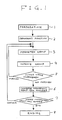
- Fig. 1 shows a flow of the processing in the optimization system of this embodiment. As described previously, the processing is executed in accordance with the computer programs.
- a block (a means) 1 provides preparations for a main part of an optimization.
- the block 1 includes sub blocks (means) 9, 10, and 11.
- the first sub block 9 determines an objective function F for evaluating the degree of the nearness of an element organization to an objective specification by use of a numerical value. Specifically, the objective function F has a value which decreases and increases as the element organization moves toward and away from the objective specification respectively.
- the processing advances to the sub block 10 which defines or determines various parameters used in the optimization.
- the determined parameters are the iteration number N of improvement for an improvement group of cells (elements), the iteration number M of improvement for the whole elements, the concentration parameter ⁇ for reducing the number of cells in an improvement group, the number W of cells in an improvement group, an initial number Winit of cells in an improvement group, and the smallest number Wmin of cells in an improvement group which equals the number W obtained at the end of the processing.
- the processing advances to the final sub block 11 which prepares an initial element organization used at the start of the processing.
- the processing advances to a block (a means) 2 which determines a redundancy function.
- the block 2 includes sub blocks (means) 12A and 12B, and 13-17.
- the first sub block 12A initializes the variable S to 0, the variable S representing an objective evaluation function.
- the processing advances to the sub block 12B which changes the element organization at random.
- the sub block 14 following the sub block 13 restores the previous element organization.
- the processing advances to the sub block 15 which compares the number of times of the execution of the sub blocks 12-14 with the number Winit.
- the processing returns to the sub block 12.
- the processing advances to the subsequent sub block 16. Accordingly, the sub blocks 12-14 are reiterated the number of times which agrees with the number Winit.
- the sub block 17 following the sub block 16 calculates a fluctuation per the number W on the basis of the fluctuation value Fr and defines the calculated fluctuation as a redundancy function Red(W).
- the introduction of the fluctuation value Fr enables the examination of the range within which the objective function F fluctuates, thereby suitably determining the redundancy function Red(W) in the judgment on the improvement which has a redundancy. This point is one of features of the optimization system of this invention.
- the redundancy function Red(W) estimates a variation of the objective function value, which is caused by a single change of the element organization, from the fluctuation value.
- Fig. 3(b) shows a modified block 2 which includes sub blocks 17 and 18.
- the processing advances to a block (a means) 3 which determines an improvement group Dm of cells.
- the block 3 includes sub blocks (means) 19 and 20a.
- the first sub block 19 determines an element constituting the origin of an improvement group of cells. Specifically, the origin element is determined at random by use of a random number so that every group of the element organization can be an object undergoing the improvement process.
- the sub block 20a following the sub block 19 determines the improvement group Dm in consideration of the origin element.
- the element organization is varied toward an optimal organization by suppressing the value of fluctuation caused by the exchange and movement of the element organizations, an improvement is made on an element group smaller than the value of the redundancy function Red(W) which corresponds to a fluctuation per element change of the objective function value responsive to a change of the element organization including the origin element, and thereby the fluctuation is reduced to a value equal to the concentration parameter multiplied by the redundancy function Red(W) which agrees with the fluctuation of the element organization of the improvement target.
- the improvement group Dm of cells is determined by registering element groups smaller than the value of the redundancy function Red(W) which corresponds to a fluctuation per element change of the objective function value responsive to a change of the element organization including the origin element.
- an element is exchanged with the origin element through movement. After the exchange, the element is defined as the improvement group Dm if the element satisfies the condition " ⁇ (Fn-Fo)2 ⁇ 1/2 ⁇ Red(W)" where the character Fo denotes the current evaluation value and the character Fn denotes the evaluation value which occurs after the exchange.
- Fig. 4(b) shows a modified block 3 which includes sub blocks 19 and 20b.
- the first sub block 19 determines an origin element at random.
- the sub block 20b following the sub block 19 empirically determines an improvement group Dm of cells. Specifically, a W number of elements close to the origin element are used to compose the improvement group Dm.
- the processing advances to a block (a means) 4 which improves the improvement group Dm.
- the block 4 includes sub blocks (means) 21-28.
- the first sub block 21 calculates the value of the objective function F of the element organization which occurs before the improvement.
- the processing advances to the sub block 22 which determines elements related to a change of the element organization within the improvement group.
- the sub block 23 following the sub block 22 changes the elements determined in the preceding sub block 22 and generates a new element organization.
- the sub block 24 following the sub block 23 calculates the difference ⁇ F between the objective function values in the preceding element organization and the new element organization.
- the sub block 25 following the sub block 24 compares the difference ⁇ F with the product of the concentration parameter ⁇ and the redundancy function Red(W) in order to determine whether or not the new element organization is acceptable. Thus, the redundancy function Red(W) is considered in the judgment on the new element organization.
- the processing advances from the sub block 25 to the sub block 26.
- the processing advances from the sub block 25 to the sub block 27.
- the sub block 26 executes the acceptance of the new element organization.
- the sub block 27 rejects the new element organization and restores the preceding element organization.
- the processing advances to the sub block 28 which compares the number of times of the execution of the sub blocks 22-27 with the number N.
- the processing returns to the sub block 22.
- the processing exits from the block 4. Accordingly, the sub blocks 22-27 are reiterated the number of times which agrees with the number N.
- the processing advances to a block (a means) 5 which makes a judgment on the improvement of the whole elements which is executed by the previous blocks 3 and 4.
- the block 5 includes sub blocks (means) 29-31.
- the first sub block 29 compares the number of times of the execution of the improvement for the whole elements with the number M. When the number of times of the execution of the improvement for the whole elements is smaller than the number M, the processing returns to the block 3 (see Fig. 1). When the number of times of the execution of the improvement for the whole elements reaches the number M, the processing advances to the sub block 30.
- the sub block 30 calculates an average of the objective function values F.
- the sub block 31 compares the average objective function value F with the evaluation function value Fo which occurs before the improvement.
- the processing returns to the block 3 (see Fig. 1) and the same number W of cells in an improvement group is maintained.
- the processing exits from the block 5 and advances to a subsequent block 6 (see Fig. 1) which reduces the number W of cells in an improvement group as will be described later.
- the block 6 includes a sub block 32 which updates the number W of cells in an improvement group in such a manner as to reduce the number W.
- the processing advances to a block (a means) 7 which makes a judgment on the smallest number Wmin of cells in an improvement group.
- the block 7 includes sub blocks (means) 17 and 33-35.
- the first sub block 33 compares the number W of cells in an improvement group with the smallest number Wmin of cells in an improvement group. When the number W is equal to or smaller than the smallest number Wmin, the processing advances to the sub block 34. When the number W is greater than the smallest number Wmin, the processing advances to the sub block 17.
- the processing After the sub block 17, the processing returns to the block 3 (see Fig. 1).
- the sub block 34 compares the redundancy function value Red(W) with 0. When the redundancy function value Red(W) equals 0 and thus a further improvement can not be expected, the processing advances a block 8 (see Fig. 1) which finishes the processing. When the redundancy function value Red(W) differs from 0, the processing advances to the sub block 35 which sets the redundancy function value Red(W) to 0. After the sub block 35, the processing returns to the block 3 (see Fig. 1).
- the travelling salesman problem is equivalent to an optimization of substance transportation or information transmission. It is now assumed that there are cities and a salesman starts from an arbitrary one of the cities and travels to all of the cities via a path without duplication.
- the resolution of the travelling salesman problem is to determine the shortest path and the travelling orders of the cities. During the sequential travel to the cities from the starting city, if there is a path which enables the return to the starting city by only a smallest movement, such a path is optimal.
- a group of 16 cities is handled in the travelling salesman problem.
- cities T1-T16 composing a group are arranged in a two-dimensional lattice which has 4 rows and 4 columns extending in X and Y directions respectively.
- the travelling orders of the cities are represented by the respective characters C1-C16, and the connections between the adjacent cities as viewed in the travelling orders are represented by the respective characters N1-N16.
- the travelling salesman problem is equal to a problem related to the assignment of the elements C1-C16, which have the connection relations N1-N16 as shown in Fig. 9(c), to the lattice points T1-T16 of Fig. 9(a).
- An optimal element organization is equivalent to such an element assignment as to minimize the total distance of the connections N1-N16 in the assignment problem.
- the sub block 9 of the block 1 determines the objective function F by referring to the following equation.
- F ⁇ i ⁇ j (R ij )2
- the characters ⁇ i ⁇ j denote operators of calculating the summation of R for all the elements
- R ij denotes the distance between the lattice points at which the elements Ci and Cj are located respectively.
- the distance R ij equals 0 when the elements Ci and Cj have no relation of connection.
- the sub block 10 of the block 1 uses the following values.
- the number W of cells in an improvement group equals 16.
- the initial number Winit of cells in an improvement group equals 16.
- the number of the whole elements equals 16.
- the smallest number Wmin of cells in an improvement group equals 4.
- the minimum element adjacent group of cells equals 4.
- the iteration number N of improvement for an improvement group equals the number W.
- the iteration number M of improvement for the whole elements equals 20 ⁇ Winit/N, where 20 is chosen arbitrary.
- the concentration parameter ⁇ equals 0.9.
- Fig. 9(d) shows an initial element organization which is obtained by arbitrarily changing and moving the elements the Winit number of times.
- the sub block 16 of the block 2 calculates the fluctuation value Fr by referring to the following equation.
- ⁇ F denotes the difference between the objective function values Fo and Fn which occur before and after the exchange respectively.
- S denotes the summation of the squares of the respective differences ⁇ F in the case where the elements are exchanged at random the Winit number of times within the improvement group Dm.
- the processing is performed the Winit number of times. This number of times may be arbitrary.
- the fluctuation value Fr is calculated as follows.
- the maximum objective function value difference ⁇ Fmax 2 ⁇ 2 ⁇ (Winit 1/2 )2 where the respective constants "2" are determined on the basis of the fact that the number of wiring lines per element is 2 and there are two directions (X and Y directions).
- the smallest objective function value difference ⁇ Fmin is obtained by the element exchange through the smallest distance "Wmin 1/2 " characterized by the length of a side of the smallest improvement group 41 of cells which is shown in Fig. 9(e).
- the smallest objective function value difference ⁇ Fmin is expressed by the following equation.
- ⁇ Fmin 2 ⁇ 2 ⁇ (Wmin 1/2 )2
- the fluctuation value Fr is defined as being equal to an average between the maximum difference ⁇ Fmax and the minimum difference ⁇ Fmin. Therefore, the fluctuation value Fr is expressed by the following equation.
- Fr 2 ⁇ 2 ⁇ (Winit + Wmin) ⁇ /2
- the redundancy function Red(W) is expressed by the following equation.
- Red(W) 2 ⁇ (Winit + Wmin)/Winit ⁇ 2
- the redundancy function value Red(W) is fixed.
- the exchange and movement of elements within the improvement group generates a new element organization.
- the judgment on the acceptance and the rejection of the new element organization uses the redundancy function Red(W) multiplied by the concentration parameter ⁇ as will be described later.
- the sub block 19 of the block 3 determines an origin element at random.
- the improvement group Dm is formed by the element group having an element group number equal to or smaller than the value W where the objective function value remains within a given value under the change of the element organization including the origin element.
- the improvement group Dm is determined as follows.
- an origin element is defined as being located at the left-hand low corner of an improvement group Dm.
- the improvement group Dm is determined in accordance with the selection of the origin element.
- the determined improvement group Dm corresponds to a rectangle defined by the broken lines.
- the vertexes of the rectangle of the improvement group Dm have the following coordinates: (Xg, Yg), (Xg+W 1/2 -1, Yg), (Xg, Yg+W 1/2 -1), and (Xg+W 1/2 -1, Yg+W 1/2 -1).
- the block 4 generally functions to minimize the objective function value by exchanging and moving elements within the improvement group Dm. Here, only exchange is performed. The sequence of the exchange will be indicated below.
- the sub block 29 of the block 5 judges whether or not the blocks 3 and 4 are executed the M number of times, in order to confirm that improvement groups are set throughout the whole or global element organization.
- the sub block 30 of the block 5 calculates the objective function F which occurs after the improvement.
- the sub block 31 of the block 5 compares the value F and the value Fo. When the value F is smaller than the value Fo, the processing advances to the block 3 and the same number of cells in an improvement group is maintained. When the value F is not smaller than the value Fo, the processing advances to the block 6 since a further improvement can not be expected.
- the block 7 determines whether the processing should be continued or finished.
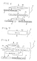
- Fig. 9 shows a final element organization which is obtained as a result of the processing. As understood from Fig. 9, the final element organization agrees with an optimal element organization which has the shortest path N1-N16 connecting the elements C1-C16.
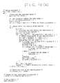
- Figs. 10(a)-10(f) show the programs used in the processing.
- Figs. 10(a) and 10(b) show the first half and the second half of a main program.
- Fig. 10(c) shows a program for generating input information and an initial placement.
- Fig. 10(d) shows a program related to processes of selecting cell elements and exchanging cell elements.
- Fig. 10(e) shows a program related to processes of calculating an objective function F and outputting a drawing.
- the programs are written in standard C language.
- Fig. 11 shows the relation between the objective function value and the number of times of the execution of the reiterative portion of the processing.
- the optimization system of this embodiment is capable of deriving an optimal cell placement in consideration of the whole cells. This feature is understood from the following fact. As shown at the stages E1-E3, after a locally-improved placement is obtained which has a first minimal objective function value, the improvement processing changes the locally-improved placement to a worse placement having a higher objective function value and then the improvement processing changes the worse placement to an excellent placement which has an objective function value smaller than the first minimal objective function value and which is better than the locally-improved placement.
- the bipartitional min-cut problem arises in the designing of an LSI logic circuit. It is now assumed that elements of a logic circuit are separated into two groups.
- the bipartitional min-cut problem relates to the determination of a combination of the separation in which the relation of the connection between the two groups or the nets crossing between the two groups is the sparsest and the area occupied by the circuit elements in the first group is as close as possible to the area occupied by the circuit elements in the second group.
- Fig. 12(a) shows a logic circuit having circuit elements C1-C12 and the connection net relation N1-N16 therebetween.
- Fig. 12(b) shows an initial element organization in which circuit elements C1-C12 are separated at random into two groups "a" and "b".
- Figs. 12(c) -12(f) shows intermediate element organizations obtained in the processing by this embodiment.
- Fig. 12(g) shows a final element organization obtained as a result of the processing by this embodiment.
- the sub block 9 of the block 1 determines the objective function F by referring to the following equation.
- F ⁇ i (K i )2
- the character ⁇ i denotes an operator of calculating the summation of K for all the elements
- the character K i denotes a function whose value is 0 when the "i"-th net corresponds to a net between circuit elements within the same separated group, and whose value is 1 when the "i"-th net corresponds to a net between circuit elements within the respective separated groups.
- the sub block 10 of the block 1 uses the following values.
- the number W of cells in an improvement group equals 12.
- the initial number Winit of cells in an improvement group equals 12.
- the number of the whole elements related to the crossing nets equals 12.
- the smallest number Wmin of cells in an improvement group which relate to the crossing nets equals 0.
- the iteration number N of improvement for an improvement group equals the number W.
- the iteration number M of improvement for the whole elements equals 20 ⁇ Winit/N, where 20 is chosen arbitrary.
- the concentration parameter ⁇ equals 0.9.
- the sub block 11 of the block 1 exchanges elements at random and thereby generates an initial element organization of Fig. 12(b).
- the fluctuation value Fr is calculated as follows.
- the number of wiring lines connecting to each element is 3 so that the maximum objective function value difference ⁇ Fmax is expressed by the following equation.
- the smallest objective function value difference ⁇ Fmin is expressed by the following equation.
- ⁇ Fmin 0
- the redundancy function Red(W) is expressed by the following equation.
- Red(W) 3/Winit ⁇ W
- Red(W) 3/Winit ⁇ W
- the sub block 19 of the block 3 selects a crossing net 43 (see Fig 12) at random and defines an element connecting to the crossing net 43 as an origin element.
- the sub block 19 is followed by the sub block 20b.
- the sub block 20b selects crossing nets 43 until the number W of cells in an improvement group is reached, and the sub block 20b adds elements, connecting the selected crossing nets 43, into the improvement group Dm. In this way, the improvement group Dm is determined.
- the elements 44 within the improvement groups Dm are represented by hatched circles.
- the block 4 generally functions to minimize the objective function value by exchanging the elements 44 within the improvement group Dm.
- the sequence of the exchange will be indicated below.
- the sub block 29 of the block 5 judges whether or not the blocks 3 and 4 are executed the M number of times, in order to confirm that improvement groups are set throughout the whole element organization.
- the sub block 30 of the block 5 calculates the objective function F which occurs after the improvement.
- the sub block 31 of the block 5 compares the value F and the value Fo. When the value F is smaller than the value Fo, the processing advances to the block 3 and the same number of cells in an improvement group is maintained. When the value F is not smaller than the value Fo, the processing advances to the block 6 since a further improvement can not be expected.
- the block 7 determines whether the processing should be continued or finished.
- Fig. 12(c) all of the elements connecting to at least one of the crossing nets N1, N3, N16, N15, N13, N12, N11, N10, N8, N6, and N5 are represented by the hatched circles and compose the improvement group.
- the improvement and concentration processing changes the element organization of Fig. 12(c) into an element organization of Fig. 12(d).
- Fig. 12(d) six elements connecting the crossing nets N16, N12, and N4 and represented by the hatched circles compose the improvement group.
- the further improvement and concentration processing changes the element organization of Fig. 12(d) into an element organization of Fig. 12(e).
- Fig. 12(e) three elements connecting the crossing nets N6 and N8 and represented by the hatched circles compose the improvement group.
- Fig. 12(f) shows another element organization at the number W of cells in an improvement group which is the same as that in the case of Fig. 12(e).
- Fig. 12(f) four elements connecting the crossing nets N11 and N7 and represented by the hatched circles compose the improvement group.
- Fig. 12(g) shows a final element organization which is obtained as a result of the processing. As understood from Fig. 12(g), the final element organization agrees with an optimal element organization in which the number of crossing nets is the smallest and the same numbers of the elements reside in the respective two separated groups.
- the block 1 for determining the number of cells (elements) in an improvement group and the block 3 for determining an improvement group of cells enables the efficient improvement of the element organization.
- the efficient improvement results in a low CPU cost.
- the block 2 determines the redundancy function in consideration of the fluctuation in the value of the objective function of the element organization
- the block 4 can perform suitable changes of the improvement group by use of the definite redundancy. Since the sub block 25 of the block 4 enables temporal acceptance of an element placement which is worse than the preceding element placement by a degree dependent on the concentration parameter and the redundancy function value, a final cell placement can be obtained in consideration of the global or whole cell placement but regardless of whether or not a local cell placement is good.
- the final cell placement can be adequately close to an optimal cell placement.
- the block 6 reduces the number of cells in an improvement group by using the function synchronous with the number of cells in an improvement group, and the redundancy can be converged.
- the sub block 35 of the block 7 sets the redundancy to 0 and thus the optimization processing can be converged. Accordingly, the finally-obtained element organization is stable and excellent.
- an element organization is gradually changed toward an objective specification by local changes of the element organization.
- a value of an objective function depends on a degree of a nearness of the element organization to the objective specification.
- a redundancy function of a number of elements in an improvement group is determined in consideration of a fluctuation in the value of the objective function, so that suitable changes of the improvement group are performed by use of the definite redundancy.
- An intermediate element organization is rejected and accepted in accordance with the redundancy function value, so that a final element organization can be obtained in consideration of a global aspect of the element organization.
Landscapes
- Engineering & Computer Science (AREA)
- Physics & Mathematics (AREA)
- Business, Economics & Management (AREA)
- Theoretical Computer Science (AREA)
- Human Resources & Organizations (AREA)
- General Physics & Mathematics (AREA)
- Economics (AREA)
- Computer Hardware Design (AREA)
- Strategic Management (AREA)
- General Engineering & Computer Science (AREA)
- Entrepreneurship & Innovation (AREA)
- Geometry (AREA)
- Quality & Reliability (AREA)
- General Business, Economics & Management (AREA)
- Operations Research (AREA)
- Marketing (AREA)
- Architecture (AREA)
- Game Theory and Decision Science (AREA)
- Evolutionary Computation (AREA)
- Tourism & Hospitality (AREA)
- Development Economics (AREA)
- Data Mining & Analysis (AREA)
- Databases & Information Systems (AREA)
- Mathematical Physics (AREA)
- Software Systems (AREA)
- Design And Manufacture Of Integrated Circuits (AREA)
- Management, Administration, Business Operations System, And Electronic Commerce (AREA)
- Exposure And Positioning Against Photoresist Photosensitive Materials (AREA)
Applications Claiming Priority (2)
| Application Number | Priority Date | Filing Date | Title |
|---|---|---|---|
| JP273433/88 | 1988-10-28 | ||
| JP27343388 | 1988-10-28 |
Publications (3)
| Publication Number | Publication Date |
|---|---|
| EP0367154A2 true EP0367154A2 (fr) | 1990-05-09 |
| EP0367154A3 EP0367154A3 (fr) | 1991-10-16 |
| EP0367154B1 EP0367154B1 (fr) | 1997-02-26 |
Family
ID=17527839
Family Applications (1)
| Application Number | Title | Priority Date | Filing Date |
|---|---|---|---|
| EP89120029A Expired - Lifetime EP0367154B1 (fr) | 1988-10-28 | 1989-10-27 | Optimalisation de l'organisation de plusieurs éléments discrets |
Country Status (4)
| Country | Link |
|---|---|
| US (1) | US5159682A (fr) |
| EP (1) | EP0367154B1 (fr) |
| KR (1) | KR920005241B1 (fr) |
| DE (1) | DE68927794T2 (fr) |
Cited By (2)
| Publication number | Priority date | Publication date | Assignee | Title |
|---|---|---|---|---|
| EP2933693A1 (fr) * | 2014-04-17 | 2015-10-21 | Rovio Entertainment Ltd | Modification de paramètre |
| US11237527B2 (en) | 2014-04-17 | 2022-02-01 | Rovio Entertainment Ltd | Parameter modification |
Families Citing this family (47)
| Publication number | Priority date | Publication date | Assignee | Title |
|---|---|---|---|---|
| US5430831A (en) * | 1991-03-19 | 1995-07-04 | Koninklijke Ptt Nederland N.V. | Method of packing rectangular objects in a rectangular area or space by determination of free subareas or subspaces |
| JP3220250B2 (ja) * | 1992-01-09 | 2001-10-22 | 株式会社東芝 | セル自動配置方法 |
| JPH0773158A (ja) * | 1993-07-12 | 1995-03-17 | Hitachi Ltd | 計画立案方法および装置 |
| JP2922404B2 (ja) * | 1993-11-15 | 1999-07-26 | 富士通株式会社 | 集積回路の配置決定方法 |
| US5963975A (en) * | 1994-04-19 | 1999-10-05 | Lsi Logic Corporation | Single chip integrated circuit distributed shared memory (DSM) and communications nodes |
| US5557533A (en) * | 1994-04-19 | 1996-09-17 | Lsi Logic Corporation | Cell placement alteration apparatus for integrated circuit chip physical design automation system |
| US5914887A (en) * | 1994-04-19 | 1999-06-22 | Lsi Logic Corporation | Congestion based cost factor computing apparatus for integrated circuit physical design automation system |
| US5495419A (en) * | 1994-04-19 | 1996-02-27 | Lsi Logic Corporation | Integrated circuit physical design automation system utilizing optimization process decomposition and parallel processing |
| US6493658B1 (en) | 1994-04-19 | 2002-12-10 | Lsi Logic Corporation | Optimization processing for integrated circuit physical design automation system using optimally switched fitness improvement algorithms |
| US5815403A (en) * | 1994-04-19 | 1998-09-29 | Lsi Logic Corporation | Fail-safe distributive processing method for producing a highest fitness cell placement for an integrated circuit chip |
| US6155725A (en) * | 1994-04-19 | 2000-12-05 | Lsi Logic Corporation | Cell placement representation and transposition for integrated circuit physical design automation system |
| US5875117A (en) * | 1994-04-19 | 1999-02-23 | Lsi Logic Corporation | Simultaneous placement and routing (SPAR) method for integrated circuit physical design automation system |
| US5587919A (en) * | 1994-04-22 | 1996-12-24 | Lucent Technologies, Inc. | Apparatus and method for logic optimization by redundancy addition and removal |
| US5526514A (en) * | 1994-06-21 | 1996-06-11 | Pradhan; Dhiraj | Method for circuit verification and multi-level circuit optimization based on structural implications |
| US5675500A (en) * | 1994-10-18 | 1997-10-07 | International Business Machines Corporation | Multi-chip device partitioning process |
| US5852562A (en) * | 1994-12-13 | 1998-12-22 | Matsushita Electric Industrial Co., Ltd. | Method and apparatus for designing an LSI layout utilizing cells having a predetermined wiring height in order to reduce wiring zones |
| US5612894A (en) * | 1995-02-08 | 1997-03-18 | Wertz; David H. | System and method for molecular modeling utilizing a sensitivity factor |
| US5740067A (en) * | 1995-10-19 | 1998-04-14 | International Business Machines Corporation | Method for clock skew cost calculation |
| US5745735A (en) * | 1995-10-26 | 1998-04-28 | International Business Machines Corporation | Localized simulated annealing |
| US5892688A (en) * | 1996-06-28 | 1999-04-06 | Lsi Logic Corporation | Advanced modular cell placement system with iterative one dimensional preplacement optimization |
| US5867398A (en) * | 1996-06-28 | 1999-02-02 | Lsi Logic Corporation | Advanced modular cell placement system with density driven capacity penalty system |
| US5872718A (en) * | 1996-06-28 | 1999-02-16 | Lsi Logic Corporation | Advanced modular cell placement system |
| US5844811A (en) * | 1996-06-28 | 1998-12-01 | Lsi Logic Corporation | Advanced modular cell placement system with universal affinity driven discrete placement optimization |
| US5835381A (en) * | 1996-06-28 | 1998-11-10 | Lsi Logic Corporation | Advanced modular cell placement system with minimizing maximal cut driven affinity system |
| US5870312A (en) * | 1996-06-28 | 1999-02-09 | Lsi Logic Corporation | Advanced modular cell placement system with dispersion-driven levelizing system |
| US6026223A (en) * | 1996-06-28 | 2000-02-15 | Scepanovic; Ranko | Advanced modular cell placement system with overlap remover with minimal noise |
| US5808899A (en) * | 1996-06-28 | 1998-09-15 | Lsi Logic Corporation | Advanced modular cell placement system with cell placement crystallization |
| US5870311A (en) * | 1996-06-28 | 1999-02-09 | Lsi Logic Corporation | Advanced modular cell placement system with fast procedure for finding a levelizing cut point |
| US5812740A (en) * | 1996-06-28 | 1998-09-22 | Lsi Logic Corporation | Advanced modular cell placement system with neighborhood system driven optimization |
| US6030110A (en) * | 1996-06-28 | 2000-02-29 | Lsi Logic Corporation | Advanced modular cell placement system with median control and increase in resolution |
| US6085032A (en) * | 1996-06-28 | 2000-07-04 | Lsi Logic Corporation | Advanced modular cell placement system with sinusoidal optimization |
| US5914888A (en) * | 1996-06-28 | 1999-06-22 | Lsi Logic Corporation | Advanced modular cell placement system with coarse overflow remover |
| US6067409A (en) * | 1996-06-28 | 2000-05-23 | Lsi Logic Corporation | Advanced modular cell placement system |
| US5831863A (en) * | 1996-06-28 | 1998-11-03 | Lsi Logic Corporation | Advanced modular cell placement system with wire length driven affinity system |
| US5963455A (en) * | 1996-06-28 | 1999-10-05 | Lsi Logic Corporation | Advanced modular cell placement system with functional sieve optimization technique |
| US5963728A (en) * | 1996-08-14 | 1999-10-05 | International Business Machines Corporation | Method to partition clock sinks into nets |
| US5980093A (en) * | 1996-12-04 | 1999-11-09 | Lsi Logic Corporation | Integrated circuit layout routing using multiprocessing |
| US6463347B1 (en) * | 1997-09-15 | 2002-10-08 | International Paper Company | System for detecting occurrence of an event when the slope of change based upon difference of short and long term averages exceeds a predetermined limit |
| US6412096B1 (en) * | 1999-04-30 | 2002-06-25 | International Business Machines Corporation | Method and apparatus for a hedge analysis technique for performance improvements of large scale integrated circuit logic design |
| US6769098B2 (en) * | 2000-02-29 | 2004-07-27 | Matsushita Electric Industrial Co., Ltd. | Method of physical design for integrated circuit |
| US20030014225A1 (en) * | 2001-07-13 | 2003-01-16 | De Vicente Juan Francisco | Thermodynamic simulated annealing schedule for combinatorial optimization problems |
| US6665851B1 (en) * | 2001-12-04 | 2003-12-16 | Synopsys, Inc. | Quick placement of electronic circuits using orthogonal one dimensional placements |
| EP1320026A1 (fr) * | 2001-12-13 | 2003-06-18 | STMicroelectronics S.r.l. | Méthode à générer une séquence des nombres aléatoires et un générateur des bits aléatoires relatif |
| US7349121B2 (en) * | 2002-08-02 | 2008-03-25 | Agfa Graphics Nv | Method for automatically determining an imposition plan |
| EP1387289A1 (fr) * | 2002-08-02 | 2004-02-04 | Agfa-Gevaert | Procédé de determination automatique d'un plan d'imposition |
| US8347261B2 (en) * | 2009-09-10 | 2013-01-01 | Cadence Design Systems, Inc. | Method and system for implementing graphically editable parameterized cells |
| EP3334282B1 (fr) | 2015-08-14 | 2022-12-21 | Imertech Sas | Particule inorganique contenat du métal antimicrobiens |
Family Cites Families (8)
| Publication number | Priority date | Publication date | Assignee | Title |
|---|---|---|---|---|
| FR1502554A (fr) * | 1965-12-01 | 1968-02-07 | ||
| US3681782A (en) * | 1970-12-02 | 1972-08-01 | Honeywell Inf Systems | Machine process for positioning interconnected components to minimize interconnecting line length |
| US4495559A (en) * | 1981-11-02 | 1985-01-22 | International Business Machines Corporation | Optimization of an organization of many discrete elements |
| US4630219A (en) * | 1983-11-23 | 1986-12-16 | International Business Machines Corporation | Element placement method |
| US4615011A (en) * | 1983-12-19 | 1986-09-30 | Ibm | Iterative method for establishing connections and resulting product |
| US4754408A (en) * | 1985-11-21 | 1988-06-28 | International Business Machines Corporation | Progressive insertion placement of elements on an integrated circuit |
| JPH0793358B2 (ja) * | 1986-11-10 | 1995-10-09 | 日本電気株式会社 | ブロック配置処理方式 |
| US4931944A (en) * | 1988-05-27 | 1990-06-05 | General Motors Corporation | Method of optimizing a vehicle assembly line build sequence |
-
1989
- 1989-10-26 US US07/426,957 patent/US5159682A/en not_active Expired - Fee Related
- 1989-10-27 EP EP89120029A patent/EP0367154B1/fr not_active Expired - Lifetime
- 1989-10-27 DE DE68927794T patent/DE68927794T2/de not_active Expired - Fee Related
- 1989-10-28 KR KR1019890015603A patent/KR920005241B1/ko not_active Expired
Non-Patent Citations (3)
| Title |
|---|
| IEEE JOURNAL OF SOLID-STATE CIRCUITS. vol. SC-20, no. 2, April 1985, NEW YORK US pages 510 - 522; SECHEN ET AL: 'the timberwolf placement and routing package ' * |
| IEEE TRANSACTIONS ON COMPUTER AIDED DESIGN OF INTEGRATED CIRCUITS AND SYSTEMS vol. CAD-6, no. 2, March 1987, NEW YORK US pages 211 - 221; SIARRY ET AL: 'THERMODYNAMIC OPTIMIZATION OF BLOCK PLACEMENT ' * |
| SCIENCE vol. 220, no. 4598, May 13, 1983, pages 671 - 680; KIRKPATRICK ET AL: 'optimization by simulated annealing ' * |
Cited By (2)
| Publication number | Priority date | Publication date | Assignee | Title |
|---|---|---|---|---|
| EP2933693A1 (fr) * | 2014-04-17 | 2015-10-21 | Rovio Entertainment Ltd | Modification de paramètre |
| US11237527B2 (en) | 2014-04-17 | 2022-02-01 | Rovio Entertainment Ltd | Parameter modification |
Also Published As
| Publication number | Publication date |
|---|---|
| DE68927794T2 (de) | 1997-09-18 |
| KR900006881A (ko) | 1990-05-09 |
| EP0367154A3 (fr) | 1991-10-16 |
| DE68927794D1 (de) | 1997-04-03 |
| EP0367154B1 (fr) | 1997-02-26 |
| US5159682A (en) | 1992-10-27 |
| KR920005241B1 (ko) | 1992-06-29 |
Similar Documents
| Publication | Publication Date | Title |
|---|---|---|
| EP0367154B1 (fr) | Optimalisation de l'organisation de plusieurs éléments discrets | |
| US4916627A (en) | Logic path length reduction using boolean minimization | |
| US5237514A (en) | Minimizing path delay in a machine by compensation of timing through selective placement and partitioning | |
| US6415427B2 (en) | Method and apparatus for global routing, and storage medium having global routing program stored therein | |
| US5930499A (en) | Method for mixed placement of structured and non-structured circuit elements | |
| US5222031A (en) | Logic cell placement method for semiconductor integrated circuit | |
| US5168455A (en) | Procedure for incorporating timing parameters in the synthesis of logic circuit designs | |
| US5140402A (en) | Automatic placement method for arranging logic cells | |
| US7089521B2 (en) | Method for legalizing the placement of cells in an integrated circuit layout | |
| JP3001403B2 (ja) | 論理回路のレイアウト方法 | |
| US6066178A (en) | Automated design method and system for synthesizing digital multipliers | |
| Hutton et al. | Characterization and parameterized generation of synthetic combinational benchmark circuits | |
| Ho et al. | A hybrid approach for concurrent layout design of cells and their flow paths in a tree configuration | |
| US6031979A (en) | Circuit partitioning apparatus for executing parallel circuit simulation and method therefor | |
| US6564361B1 (en) | Method and apparatus for timing driven resynthesis | |
| US7139987B2 (en) | Analog integrated circuit layout design | |
| US6681373B1 (en) | Method and apparatus for dynamic buffer and inverter tree optimization | |
| US6532582B1 (en) | Method and apparatus for optimal critical netlist area selection | |
| US6637011B1 (en) | Method and apparatus for quick search for identities applicable to specified formula | |
| US11144700B1 (en) | Grouping nets to facilitate repeater insertion | |
| US6243850B1 (en) | Allocation apparatus and method for determining cell allocation of semiconductor circuit | |
| US6507939B1 (en) | Net delay optimization with ramptime violation removal | |
| JP3182244B2 (ja) | 半導体集積回路における信号伝播遅延時間の最適化方法 | |
| US20240232497A1 (en) | Method for Generating Placement and Routing for an Integrated Circuit (IC) | |
| US20240046013A1 (en) | Chip placement method and apparatus, and storage medium |
Legal Events
| Date | Code | Title | Description |
|---|---|---|---|
| PUAI | Public reference made under article 153(3) epc to a published international application that has entered the european phase |
Free format text: ORIGINAL CODE: 0009012 |
|
| 17P | Request for examination filed |
Effective date: 19891027 |
|
| AK | Designated contracting states |
Kind code of ref document: A2 Designated state(s): DE FR GB |
|
| PUAL | Search report despatched |
Free format text: ORIGINAL CODE: 0009013 |
|
| AK | Designated contracting states |
Kind code of ref document: A3 Designated state(s): DE FR GB |
|
| 17Q | First examination report despatched |
Effective date: 19950206 |
|
| GRAG | Despatch of communication of intention to grant |
Free format text: ORIGINAL CODE: EPIDOS AGRA |
|
| GRAH | Despatch of communication of intention to grant a patent |
Free format text: ORIGINAL CODE: EPIDOS IGRA |
|
| GRAH | Despatch of communication of intention to grant a patent |
Free format text: ORIGINAL CODE: EPIDOS IGRA |
|
| GRAA | (expected) grant |
Free format text: ORIGINAL CODE: 0009210 |
|
| AK | Designated contracting states |
Kind code of ref document: B1 Designated state(s): DE FR GB |
|
| ET | Fr: translation filed | ||
| REF | Corresponds to: |
Ref document number: 68927794 Country of ref document: DE Date of ref document: 19970403 |
|
| PLBE | No opposition filed within time limit |
Free format text: ORIGINAL CODE: 0009261 |
|
| STAA | Information on the status of an ep patent application or granted ep patent |
Free format text: STATUS: NO OPPOSITION FILED WITHIN TIME LIMIT |
|
| 26N | No opposition filed | ||
| PGFP | Annual fee paid to national office [announced via postgrant information from national office to epo] |
Ref country code: FR Payment date: 20001010 Year of fee payment: 12 |
|
| PGFP | Annual fee paid to national office [announced via postgrant information from national office to epo] |
Ref country code: DE Payment date: 20001023 Year of fee payment: 12 |
|
| PGFP | Annual fee paid to national office [announced via postgrant information from national office to epo] |
Ref country code: GB Payment date: 20001025 Year of fee payment: 12 |
|
| PG25 | Lapsed in a contracting state [announced via postgrant information from national office to epo] |
Ref country code: GB Free format text: LAPSE BECAUSE OF NON-PAYMENT OF DUE FEES Effective date: 20011027 |
|
| REG | Reference to a national code |
Ref country code: GB Ref legal event code: IF02 |
|
| GBPC | Gb: european patent ceased through non-payment of renewal fee |
Effective date: 20011027 |
|
| PG25 | Lapsed in a contracting state [announced via postgrant information from national office to epo] |
Ref country code: FR Free format text: LAPSE BECAUSE OF NON-PAYMENT OF DUE FEES Effective date: 20020628 |
|
| PG25 | Lapsed in a contracting state [announced via postgrant information from national office to epo] |
Ref country code: DE Free format text: LAPSE BECAUSE OF NON-PAYMENT OF DUE FEES Effective date: 20020702 |
|
| REG | Reference to a national code |
Ref country code: FR Ref legal event code: ST |