EP0367155A2 - Extremely high frequency oscillator - Google Patents
Extremely high frequency oscillator Download PDFInfo
- Publication number
- EP0367155A2 EP0367155A2 EP89120031A EP89120031A EP0367155A2 EP 0367155 A2 EP0367155 A2 EP 0367155A2 EP 89120031 A EP89120031 A EP 89120031A EP 89120031 A EP89120031 A EP 89120031A EP 0367155 A2 EP0367155 A2 EP 0367155A2
- Authority
- EP
- European Patent Office
- Prior art keywords
- energy
- waveguide
- electrons
- high frequency
- section
- Prior art date
- Legal status (The legal status is an assumption and is not a legal conclusion. Google has not performed a legal analysis and makes no representation as to the accuracy of the status listed.)
- Granted
Links
- 238000010894 electron beam technology Methods 0.000 claims abstract description 23
- 230000005291 magnetic effect Effects 0.000 claims abstract description 22
- 230000001902 propagating effect Effects 0.000 claims abstract description 22
- 241001663154 Electron Species 0.000 claims description 7
- 238000006243 chemical reaction Methods 0.000 description 17
- 230000005672 electromagnetic field Effects 0.000 description 7
- 238000009826 distribution Methods 0.000 description 6
- 230000003993 interaction Effects 0.000 description 6
- 238000005094 computer simulation Methods 0.000 description 4
- 230000003247 decreasing effect Effects 0.000 description 4
- 238000004088 simulation Methods 0.000 description 4
- 238000011144 upstream manufacturing Methods 0.000 description 4
- 230000001133 acceleration Effects 0.000 description 3
- 230000000694 effects Effects 0.000 description 3
- 230000005684 electric field Effects 0.000 description 2
- 230000007246 mechanism Effects 0.000 description 2
- 230000010355 oscillation Effects 0.000 description 2
- 238000005191 phase separation Methods 0.000 description 2
- 206010013710 Drug interaction Diseases 0.000 description 1
- 230000000994 depressogenic effect Effects 0.000 description 1
Images


Classifications
-
- H—ELECTRICITY
- H01—ELECTRIC ELEMENTS
- H01J—ELECTRIC DISCHARGE TUBES OR DISCHARGE LAMPS
- H01J25/00—Transit-time tubes, e.g. klystrons, travelling-wave tubes, magnetrons
- H01J25/02—Tubes with electron stream modulated in velocity or density in a modulator zone and thereafter giving up energy in an inducing zone, the zones being associated with one or more resonators
- H01J25/025—Tubes with electron stream modulated in velocity or density in a modulator zone and thereafter giving up energy in an inducing zone, the zones being associated with one or more resonators with an electron stream following a helical path
Definitions
- the present invention relates to an extremely high frequency oscillator and, more particularly to an extremely high frequency oscillator having a high frequency circuit assembly comprising a resonant cavity and a waveguide, wherein each of electrons gyrating within a DC magnetic field interacts with TE-mode electromagnetic waves propagating within the high frequency circuit assembly, thereby to oscillate electromagnetic waves having wavelengths in the order of millimeters to sub-millimeters.
- a peniotron is a high power electron tube which comprises a high frequency circuit assembly and oscillates or amplifies electromagnetic waves by virtue of the phase-separation effect resulting from the interaction between electrons gyrating within a DC magnetic field and the electromagnetic waves propagating within the circuit assembly.
- the peniotron utilizes the effect resulting from the movements of guiding centers around which electrons gyrated in a spatially non-uniform, high frequency electromagnetic field. Each electron is alternately accelerated and decelerated every time it gyrates around the guiding center. The accelerations and decelerations of each electron are gradually accumulated. In this interaction, the successive deceleration is stronger than the previous acceleration. A kinetic energy of each electron corresponding to accumulated deceleration is converted into the high frequency electromagnetic energy.
- the essential feature of the operating mechanism of the peniotron is the energy exchange between the individual electrons and the high frequency electromagnetic field.
- the operating mechanism of the peniotron are basically different from that of the klystron or the gyrotron in which the electromagnetic field is amplified or oscillated because a bunching of electrons interacts with the electromagnetic field.
- the peniotron can perform an operation wherein electrons act, independent of a phase relationship between the electrons and the high frequency electromagnetic field. All of the electrons are therefore trapped within the deceleration electric field of the electromagnetic waves due to the phase-separation effect.
- all gyrating kinetic energy of the electrons can be converted into the energy of the electromagnetic waves.
- the efficiency of the energy conversion, from the electrons to the electromagnetic waves can be expected to be extremely high.
- the conventional oscillator cannot convert the kinetic energy acing in the longitudinal direction of the tube into the energy of electromagnetic waves. It is impossible with the prior-art oscillator to increase the energy-conversion efficiency to a near-100% value, unless the oscillator is equipped with a perfect depressed collector.
- Another problem with the conventional oscillator is that, the higher the frequency of the electromagnetic waves, the smaller the resonant cavity and waveguide of the high frequency circuit assembly should be. The smaller the resonant cavity and the waveguide, the lower the withstand electric power, because a permissible electric power loss of the circuit is restricted.
- the oscillator requires an intense DC magnetic field, and the frequency of the electromagnetic waves is limited. The oscillators, developed thus far, can output 10 kW at an operating frequency of 45 GHz at best.
- an extremely high frequency oscillator in which each of gyrating electrons, i.e., circulating and traveling electrons and TE-mode electromagnetic waves interact within a high frequency circuit assembly, satisfying auto-resonant conditions when the phase velocity Vp of the waves is equal to, or nearly equal to, the light velocity c.
- the high frequency circuit assembly comprises a resonant cavity and a propagating waveguide connected to the downstream-end of the cavity.
- the high frequency power being oscillated in the cavity is sufficiently suppressed to a value less than that of the high frequency power being output from the waveguide.
- the extremely high frequency oscillator of this invention is named as an auto-resonant peniotron in this specification.
- the oscillator performs a preliminary, low-power oscillation within the auto-resonant cavity. More specifically, electrons interact in the cavity to a relatively low degree, with a TE-mode electromagnetic field propagating along the beam. Accordingly, reflection electromagnetic waves produced in the cavity does not affect the auto-resonant conditions so that the auto-resonant conditions are always maintained. The behavior variations of the electrons are suppressed.
- the oscillating power level in the cavity can be set by selecting Q value of the cavity. A beam of the electrons passing through the cavity and the electromagnetic waves are emerged in the propagating waveguide. In the waveguide, the beam and the wave interact while maintaining the auto-resonant conditions. Therefore, not only the circulating kinetic energy of the electrons, but also the traveling kinetic energy of the electrons serve to intensify the electromagnetic field within the propagating waveguide. Hence, the oscillator has a high energy-conversion efficiency.
- Fig. 1 schematically illustrates a peniotron, which is an embodiment of the present invention.
- the peniotron comprises an electron gun assembly 11, a beam-guiding section 12 coupled to the gun assembly 11, and a resonant cavity section 13 connected to the beam-guiding section 12.
- the electron gun assembly 11 extends in the axis z of the peniotron.
- the section 12 guides the electron beam emitted from the assembly 11 into the resonance cavity section 13.
- the peniotron further comprises a propagating wave guide 14 connected to the downstream end of the section 13, a collector section 15 coupled to the output end of the waveguide 14, and an output waveguide 17 coupled to the output end of the collector 15.
- the propagating waveguide 14 has the same cross section as the resonant cavity section 13 and the collector section 15 is designed to collect electrons.
- a window 16, which is a dielectric member, is located within the junction between the collector section 15 and the output waveguide 17, and attached in airtight fashion to the inner surface of the junction.
- the peniotron further comprises three solenoid coil units 18, 19, and 20.
- the coil units 18 and 19 surround the electron gun assembly 11.
- the coil unit 20 surrounds both the resonance cavity section 13 and the propagating waveguide 14.
- the electron gun assembly 11 has a cathode 21 and an accelerating anode 22.
- the cathode 21 emits electrons from its circumferential region when it is heated.
- the anode 22 accelerates the electrons emitted from the cathode 21.
- the electron gun assembly 11 emits a hollow electron beam e.
- the solenoid coil units 18 and 19, both surrounding the electron gun assembly 11, generate DC magnetic fields having predetermined intensities. Due to these DC magnetic fields, each electron of the hollow electron beam e is gyrated.
- the solenoid coil unit 20 generates a DC magnetic field having a predetermined intensity and extending almost parallel to the axis z of the peniotron, which causes the electrons of the electron beam e to gyrate at predetermined cycle.
- the resonant cavity section 13 and the propagating waveguide 14 has inner diameter far greater than the wave length of the electromagnetic waves oscillated in the peniotron. This enables the electromagnetic waves of a predetermined mode to propagate through the waveguide 14 at a phase velocity Vp which is nearly equal to light velocity c. As a result, the interior of the cavity and waveguide remains under auto-resonant conditions.
- a predetermined mode in which a high frequency electric field is more intense in a region remote from the gyrating center around which the electron circulates, than in a region close to that center.
- modes are: the TE11 mode for a waveguide having a rectangular cross section, and TE21 mode for a waveguide having a circular cross section.
- the interaction occurs in the resonant cavity section 13 between the gyrating electron and the electromagnetic waves of a specified mode.
- This electron-wave interaction imparts part of the kinetic energy of the electron to the electromagnetic wave.
- Electromagnetic waves of specific strength and mode are thereby oscillated.
- the electromagnetic waves thus oscillated propagates and the electron beam travels from the resonance cavity 13 into the waveguide 14.
- the waves interact with the electron beam and are intensified or amplified.
- the peniotron which operates as has been described, can convert the kinetic energy of the electrons to the energy of electromagnetic waves with a high efficiency. It will be explained how the peniotron achieves a high energy-conversion efficiency.
- Fig. 2 shows the relationship between the kinetic energy Eel of the electron beam and the position within the waveguide 14, the relationship having been determined by computer simulation wherein the mode TE21 was selected for the waveguide 14 and auto-resonant conditions were set.
- FIG. 2 illustrates how the average kinetic energy of 24 sample electrons having different incidence phases in respect to the TE mode changes as they travel through the waveguide 14 along the axis z thereof, toward the output end of the waveguide 14.
- the curve shown in Fig. 2 indicates, all gyrating electrons forming the beam impart their respective energies to the electromagnetic waves and then lose energy -- substantially at the same time, as if a single electron gave great energy to the electromagnetic waves and lost its energy.
- the peniotron achieved a maximum energy-conversion efficiency of 95%.
- the peniotron shown in Fig. 1 can convert the kinetic energy of an electron beam to that of electromagnetic waves with an efficiency which is nearly equal to 100%, if the peniotron is maintained under an optimum operation condition.
- the electromagnetic wave is oscillated in the cavity at low power and the the reminders of the kinetic energies are almost converted into the electromagnetic wave in the waveguide section 14. Accordingly, it is possible that the oscillator has a high energy-conversion efficiency, as shown in Fig. 2.
- Fig. 3 is a graph representing the relationship between the energy-conversion efficiency ⁇ and the power oscillated in the resonance cavity section 13, the relationship being the results of the computer simulation.
- the target high frequency power was set at about 6.4 MW.
- the energy-conversion efficiency can be maintained over 90% when the 8% or less, or preferably 4% or less (needless to say, not 0%), of the target output power is oscillated within the resonance cavity section 13.
- the peniotron shown in Fig. 1 has other advantages. First, it can have a greater tube-diameter than the prior-art peniotron, since the electron interacts with the electromagnetic waves under the auto-resonant conditions, in the high frequency circuit assembly comprising the resonance cavity section 13 and the propagating waveguide 14. Secondly, it needs only a DC magnetic field which is far less intense than is required in the prior-art peniotron to oscillate electromagnetic waves at the same frequency, from a high-power electron beam. Therefore, the peniotron can oscillate electromagnetic waves, even at wavelengths in the sub-millimeter order, with high efficiency.
- the present invention is not limited to the embodiment illustrated in Fig. 1.
- the solenoid coil unit 20 can be replaced by a plurality of solenoid units which are arranged along the axis z of the peniotron.
- the coil units generate magnetic fields whose intensities differing such that these magnetic fields form a DC magnetic field extending along the axis z and having a tapered intensity distribution Bz at the downstream side of the waveguide 14 as shown in Figs. 4, 5 and 6.
- the phase velocity Vp of the electromagnetic wave is more greater than the light velocity c.
- the ideal auto-resonant conditions can not be obtained.
- the auto-resonant condition can be obtained if the DC magnetic field has the tapered intensity distribution according to the embodiment of the invention.
- this embodiment can also attain a sufficiently high energy-conversion efficiency, as will be understood from Figs. 4, 5 and 6 which represent the results of the simulation conducted by the inventors.
- the phase velocity Vp was set at 1.05 times the light velocity c, the TE21 mode was selected, and the oscillation frequency and the acceleration voltage were set at 200 GHz and 1 MV, respectively. Further, the ratio of the velocity at which the electrons are circulated, to the velocity at which they moved in the axis z was selected to be 1.109, and the intensity of the magnetic field in the upstream end of the waveguide and the inner diameter of the waveguide were set at 8.41 Tesla and 2.39 mm, respectively.
- Fig. 4 illustrates how the high frequency power P and the DC magnetic field Bz are distributed in the waveguide 14 when the high frequency power supplied to the waveguide 14 from the cavity 13 is 1 kW.
- Fig. 5 shows how the power P and the magnetic field Bz are distributed in the waveguide 14 when the high frequency power supplied to the waveguide 14 from the cavity 13 is 10 kW.
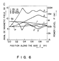
- Fig. 6 represents how the power P and the magnetic field are distributed in the waveguide 14 when the high frequency power supplied to the waveguide 14 from the cavity 13 is 100 kW.
- intensity curves 1, 2, and 3 indicate the intensity distribution of the DC magnetic field Bz which are set when the electron-beam current is 1 A, 10 A, and is 100 A, respectively.
- power curves 1, 2, and 3 represent the distributions of the high frequency power P which are calculated from the intensity distributions when the electron-beam current is 1 A, 10 A, and is 100 A, respectively.
- the high frequency power P increases as the electron beam travels toward downstream-end of the waveguide.
- the DC magnetic field is maintained at substantially constant level in the upstream portion of the waveguide 14 and gradually decreased in the downstream portion of the waveguide 14.
- the magnetic field is held almost at substantially constant level in the upstream portion of the waveguide in which the electron beam interacts within the electromagnetic waves to a low degree.
- the magnetic field is decreased gradually in the downstream portion in which the interaction between the beam and the electromagnetic waves is increased and the auto-resonant conditions which are changed due to the changes of the electron mass and the velocity of the electrons, are corrected by the tapered distribution 1, 2 or 3 of the curve Bz.
- the peniotron according to the second embodiment can also attain a high energy-conversion efficiency and output a high frequency power.
- the peniotron comprises a high frequency circuit assembly having a resonant cavity section and a propagating waveguide connected to the downstream end of the resonance cavity section.
- the circuit assembly electron gyrates, and electromagnetic waves are oscillated and amplified.
- the electrons and the waves interact, while satisfying conditions required for auto-resonance. More specifically, the electron beam interacts with the electromagnetic waves to a low degree in the cavity and the upstream portion of the waveguide, generating a high frequency power of a value far less than the target value, and then interacts with the waves to a sufficient degree in the downstream portion of the waveguide, thereby generating a high frequency power of the target value.
- both the resonant cavity section and the propagating waveguide have inner diameter greater than those of their counterpart incorporated in the conventional peniotron. Due to the two-step interaction between the electron beam and the electromagnetic waves, and also the use of the resonant cavity section and the waveguide, either having a large inner diameter, the peniotron according to the invention can convert an electron beam into a high frequency high power with high energy-conversion efficiency.
Landscapes
- Microwave Tubes (AREA)
Abstract
Description
- The present invention relates to an extremely high frequency oscillator and, more particularly to an extremely high frequency oscillator having a high frequency circuit assembly comprising a resonant cavity and a waveguide, wherein each of electrons gyrating within a DC magnetic field interacts with TE-mode electromagnetic waves propagating within the high frequency circuit assembly, thereby to oscillate electromagnetic waves having wavelengths in the order of millimeters to sub-millimeters.
- One of the known electron tubes of this type is a peniotron. As is disclosed in Japanese Patent Publication No. 45-35334 and Japanese Patent Disclosure No. 61-273833, a peniotron is a high power electron tube which comprises a high frequency circuit assembly and oscillates or amplifies electromagnetic waves by virtue of the phase-separation effect resulting from the interaction between electrons gyrating within a DC magnetic field and the electromagnetic waves propagating within the circuit assembly.
- The peniotron utilizes the effect resulting from the movements of guiding centers around which electrons gyrated in a spatially non-uniform, high frequency electromagnetic field. Each electron is alternately accelerated and decelerated every time it gyrates around the guiding center. The accelerations and decelerations of each electron are gradually accumulated. In this interaction, the successive deceleration is stronger than the previous acceleration. A kinetic energy of each electron corresponding to accumulated deceleration is converted into the high frequency electromagnetic energy. The essential feature of the operating mechanism of the peniotron is the energy exchange between the individual electrons and the high frequency electromagnetic field. The operating mechanism of the peniotron are basically different from that of the klystron or the gyrotron in which the electromagnetic field is amplified or oscillated because a bunching of electrons interacts with the electromagnetic field. Hence, the peniotron can perform an operation wherein electrons act, independent of a phase relationship between the electrons and the high frequency electromagnetic field. All of the electrons are therefore trapped within the deceleration electric field of the electromagnetic waves due to the phase-separation effect. In theory, all gyrating kinetic energy of the electrons can be converted into the energy of the electromagnetic waves. In view of this, the efficiency of the energy conversion, from the electrons to the electromagnetic waves, can be expected to be extremely high.
- The conventional oscillator, described above, cannot convert the kinetic energy acing in the longitudinal direction of the tube into the energy of electromagnetic waves. It is impossible with the prior-art oscillator to increase the energy-conversion efficiency to a near-100% value, unless the oscillator is equipped with a perfect depressed collector. Another problem with the conventional oscillator is that, the higher the frequency of the electromagnetic waves, the smaller the resonant cavity and waveguide of the high frequency circuit assembly should be. The smaller the resonant cavity and the waveguide, the lower the withstand electric power, because a permissible electric power loss of the circuit is restricted. Further, the oscillator requires an intense DC magnetic field, and the frequency of the electromagnetic waves is limited. The oscillators, developed thus far, can output 10 kW at an operating frequency of 45 GHz at best.
- Accordingly, it is the object of this invention to provide a high-power, extremely high frequency oscillator which satisfies auto-resonant conditions required for oscillating high frequency electromagnetic waves, has, therefore, a energy-conversion efficiency as high as a theoretical energy-conversion efficiency of the peniotron, and can oscillate electromagnetic waves having wavelengths in the order of millimeters to sub-millimeters.
- According to the present invention, there is provided an extremely high frequency oscillator, in which each of gyrating electrons, i.e., circulating and traveling electrons and TE-mode electromagnetic waves interact within a high frequency circuit assembly, satisfying auto-resonant conditions when the phase velocity Vp of the waves is equal to, or nearly equal to, the light velocity c. The high frequency circuit assembly comprises a resonant cavity and a propagating waveguide connected to the downstream-end of the cavity. The high frequency power being oscillated in the cavity is sufficiently suppressed to a value less than that of the high frequency power being output from the waveguide. The extremely high frequency oscillator of this invention is named as an auto-resonant peniotron in this specification.
- The oscillator performs a preliminary, low-power oscillation within the auto-resonant cavity. More specifically, electrons interact in the cavity to a relatively low degree, with a TE-mode electromagnetic field propagating along the beam. Accordingly, reflection electromagnetic waves produced in the cavity does not affect the auto-resonant conditions so that the auto-resonant conditions are always maintained. The behavior variations of the electrons are suppressed. The oscillating power level in the cavity can be set by selecting Q value of the cavity. A beam of the electrons passing through the cavity and the electromagnetic waves are emerged in the propagating waveguide. In the waveguide, the beam and the wave interact while maintaining the auto-resonant conditions. Therefore, not only the circulating kinetic energy of the electrons, but also the traveling kinetic energy of the electrons serve to intensify the electromagnetic field within the propagating waveguide. Hence, the oscillator has a high energy-conversion efficiency.
- This invention can be more fully understood from the following detailed description when taken in conjunction with the accompanying drawings, in which:
- Fig. 1 is a schematic representation of a peniotron according to the present invention;
- Fig. 2 is a graph explaining how the kinetic energy of electrons change as the electrons travel within the propagating waveguide shown in Fig. 1, in the axial direction of the oscillator;
- Fig. 3 is a graph representing the relationship between the oscillating power in the resonant cavity of the peniotron and the energy-conversion efficiency of the peniotron; and
- Figs. 4, 5, and 6 are also graphs showing the operating characteristic of another peniotron according to the present invention.
- An embodiment of the invention will now be described in detail, with reference to the accompanying drawings.
- Fig. 1 schematically illustrates a peniotron, which is an embodiment of the present invention. As is shown in Fig. 1, the peniotron comprises an electron gun assembly 11, a beam-guiding
section 12 coupled to the gun assembly 11, and aresonant cavity section 13 connected to the beam-guidingsection 12. The electron gun assembly 11 extends in the axis z of the peniotron. Thesection 12 guides the electron beam emitted from the assembly 11 into theresonance cavity section 13. - The peniotron further comprises a
propagating wave guide 14 connected to the downstream end of thesection 13, acollector section 15 coupled to the output end of thewaveguide 14, and anoutput waveguide 17 coupled to the output end of thecollector 15. The propagatingwaveguide 14 has the same cross section as theresonant cavity section 13 and thecollector section 15 is designed to collect electrons. Awindow 16, which is a dielectric member, is located within the junction between thecollector section 15 and theoutput waveguide 17, and attached in airtight fashion to the inner surface of the junction. - The peniotron further comprises three
solenoid coil units coil units 18 and 19 surround the electron gun assembly 11. Thecoil unit 20 surrounds both theresonance cavity section 13 and the propagatingwaveguide 14. - The electron gun assembly 11 has a
cathode 21 and an acceleratinganode 22. Thecathode 21 emits electrons from its circumferential region when it is heated. Theanode 22 accelerates the electrons emitted from thecathode 21. As a result, the electron gun assembly 11 emits a hollow electron beam e. Thesolenoid coil units 18 and 19, both surrounding the electron gun assembly 11, generate DC magnetic fields having predetermined intensities. Due to these DC magnetic fields, each electron of the hollow electron beam e is gyrated. Thesolenoid coil unit 20 generates a DC magnetic field having a predetermined intensity and extending almost parallel to the axis z of the peniotron, which causes the electrons of the electron beam e to gyrate at predetermined cycle. Theresonant cavity section 13 and the propagatingwaveguide 14 has inner diameter far greater than the wave length of the electromagnetic waves oscillated in the peniotron. This enables the electromagnetic waves of a predetermined mode to propagate through thewaveguide 14 at a phase velocity Vp which is nearly equal to light velocity c. As a result, the interior of the cavity and waveguide remains under auto-resonant conditions. The electromagnetic waves oscillated in the peniotron shown in Fig. 1 has a predetermined mode in which a high frequency electric field is more intense in a region remote from the gyrating center around which the electron circulates, than in a region close to that center. Examples of such modes are: the TE11 mode for a waveguide having a rectangular cross section, and TE21 mode for a waveguide having a circular cross section. - The interaction occurs in the
resonant cavity section 13 between the gyrating electron and the electromagnetic waves of a specified mode. This electron-wave interaction imparts part of the kinetic energy of the electron to the electromagnetic wave. Electromagnetic waves of specific strength and mode are thereby oscillated. The electromagnetic waves thus oscillated propagates and the electron beam travels from theresonance cavity 13 into thewaveguide 14. In thewaveguide 14, the waves interact with the electron beam and are intensified or amplified. - The peniotron, which operates as has been described, can convert the kinetic energy of the electrons to the energy of electromagnetic waves with a high efficiency. It will be explained how the peniotron achieves a high energy-conversion efficiency.
- As has been pointed out, the kinetic energy of the electron beam is converted into that of electromagnetic waves in two steps. First, part of the kinetic energy is imparted to the electromagnetic waves within the
resonant cavity section 13. Then, the rest of the energy is imparted to the electromagnetic waves within the propagatingwaveguide 14 connected to the downstream end of theresonant cavity section 13. Fig. 2 shows the relationship between the kinetic energy Eel of the electron beam and the position within thewaveguide 14, the relationship having been determined by computer simulation wherein the mode TE21 was selected for thewaveguide 14 and auto-resonant conditions were set. Fig. 2 illustrates how the average kinetic energy of 24 sample electrons having different incidence phases in respect to the TE mode changes as they travel through thewaveguide 14 along the axis z thereof, toward the output end of thewaveguide 14. As the curve shown in Fig. 2 indicates, all gyrating electrons forming the beam impart their respective energies to the electromagnetic waves and then lose energy -- substantially at the same time, as if a single electron gave great energy to the electromagnetic waves and lost its energy. As is evident from Fig. 2, the peniotron achieved a maximum energy-conversion efficiency of 95%. As the results of the computer simulation suggest, the peniotron shown in Fig. 1 can convert the kinetic energy of an electron beam to that of electromagnetic waves with an efficiency which is nearly equal to 100%, if the peniotron is maintained under an optimum operation condition. - This high energy-conversion efficiency could not be attained if all kinetic energy of the electron beam were converted into high frequency energy corresponding to the whole output power of the peniotron, in the
cavity section 13 only. The inventors hereof conducted a computer simulation to determine the efficiency at which all kinetic energy of the beam could be converted to high frequency energy in theresonance cavity section 13 only. The results of this simulation was a conversion efficiency of 67% at most. This is because no auto-resonant conditions can be set within thecavity section 13. More precisely, this is because, as the electrons interact with the electromagnetic waves in only theresonant cavity section 13, their kinetic energies are non-uniformly decreased by the reflection waves generated in thecavity section 13 so that the the kinetic energies of the electrons can not uniformly converted into the electromagnetic wave. Thus, it is confirmed by the inventors that the non-uniformity of the kinetic energies is produced after the almost of the kinetic energy has been converted into the electromagnetic energy and the electrons have decreased kinetic energies. - In the oscillator shown in Fig. 1, the electromagnetic wave is oscillated in the cavity at low power and the the reminders of the kinetic energies are almost converted into the electromagnetic wave in the
waveguide section 14. Accordingly, it is possible that the oscillator has a high energy-conversion efficiency, as shown in Fig. 2. - Fig. 3 is a graph representing the relationship between the energy-conversion efficiency η and the power oscillated in the
resonance cavity section 13, the relationship being the results of the computer simulation. In this simulation, the target high frequency power was set at about 6.4 MW. As can be understood from Fig. 3, the energy-conversion efficiency can be maintained over 90% when the 8% or less, or preferably 4% or less (needless to say, not 0%), of the target output power is oscillated within theresonance cavity section 13. - Apart from the high energy-conversion efficiency, the peniotron shown in Fig. 1 has other advantages. First, it can have a greater tube-diameter than the prior-art peniotron, since the electron interacts with the electromagnetic waves under the auto-resonant conditions, in the high frequency circuit assembly comprising the
resonance cavity section 13 and the propagatingwaveguide 14. Secondly, it needs only a DC magnetic field which is far less intense than is required in the prior-art peniotron to oscillate electromagnetic waves at the same frequency, from a high-power electron beam. Therefore, the peniotron can oscillate electromagnetic waves, even at wavelengths in the sub-millimeter order, with high efficiency. - The present invention is not limited to the embodiment illustrated in Fig. 1. For instance, the
solenoid coil unit 20 can be replaced by a plurality of solenoid units which are arranged along the axis z of the peniotron. In this case, the coil units generate magnetic fields whose intensities differing such that these magnetic fields form a DC magnetic field extending along the axis z and having a tapered intensity distribution Bz at the downstream side of thewaveguide 14 as shown in Figs. 4, 5 and 6. In the actual waveguide, it is confirmed that the phase velocity Vp of the electromagnetic wave is more greater than the light velocity c. Thus, in the conventional peniotron, the ideal auto-resonant conditions can not be obtained. However, the auto-resonant condition can be obtained if the DC magnetic field has the tapered intensity distribution according to the embodiment of the invention. Accordingly, this embodiment can also attain a sufficiently high energy-conversion efficiency, as will be understood from Figs. 4, 5 and 6 which represent the results of the simulation conducted by the inventors. - In the simulation, the phase velocity Vp was set at 1.05 times the light velocity c, the TE21 mode was selected, and the oscillation frequency and the acceleration voltage were set at 200 GHz and 1 MV, respectively. Further, the ratio of the velocity at which the electrons are circulated, to the velocity at which they moved in the axis z was selected to be 1.109, and the intensity of the magnetic field in the upstream end of the waveguide and the inner diameter of the waveguide were set at 8.41 Tesla and 2.39 mm, respectively.
- Fig. 4 illustrates how the high frequency power P and the DC magnetic field Bz are distributed in the
waveguide 14 when the high frequency power supplied to thewaveguide 14 from thecavity 13 is 1 kW. Similarly, Fig. 5 shows how the power P and the magnetic field Bz are distributed in thewaveguide 14 when the high frequency power supplied to thewaveguide 14 from thecavity 13 is 10 kW. Fig. 6 represents how the power P and the magnetic field are distributed in thewaveguide 14 when the high frequency power supplied to thewaveguide 14 from thecavity 13 is 100 kW. More specifically, in each of these figures, intensity curves 1, 2, and 3 indicate the intensity distribution of the DC magnetic field Bz which are set when the electron-beam current is 1 A, 10 A, and is 100 A, respectively. Further, in each of Figs. 4, 5, and 6, power curves 1, 2, and 3 represent the distributions of the high frequency power P which are calculated from the intensity distributions when the electron-beam current is 1 A, 10 A, and is 100 A, respectively. - As can be seen from Figs. 4, 5, and 6, the high frequency power P increases as the electron beam travels toward downstream-end of the waveguide. This is because the DC magnetic field is maintained at substantially constant level in the upstream portion of the
waveguide 14 and gradually decreased in the downstream portion of thewaveguide 14. The magnetic field is held almost at substantially constant level in the upstream portion of the waveguide in which the electron beam interacts within the electromagnetic waves to a low degree. By contrast, the magnetic field is decreased gradually in the downstream portion in which the interaction between the beam and the electromagnetic waves is increased and the auto-resonant conditions which are changed due to the changes of the electron mass and the velocity of the electrons, are corrected by the tapereddistribution - As has been explained, the peniotron according to invention comprises a high frequency circuit assembly having a resonant cavity section and a propagating waveguide connected to the downstream end of the resonance cavity section. In the circuit assembly, electron gyrates, and electromagnetic waves are oscillated and amplified. The electrons and the waves interact, while satisfying conditions required for auto-resonance. More specifically, the electron beam interacts with the electromagnetic waves to a low degree in the cavity and the upstream portion of the waveguide, generating a high frequency power of a value far less than the target value, and then interacts with the waves to a sufficient degree in the downstream portion of the waveguide, thereby generating a high frequency power of the target value. It is possible that both the resonant cavity section and the propagating waveguide have inner diameter greater than those of their counterpart incorporated in the conventional peniotron. Due to the two-step interaction between the electron beam and the electromagnetic waves, and also the use of the resonant cavity section and the waveguide, either having a large inner diameter, the peniotron according to the invention can convert an electron beam into a high frequency high power with high energy-conversion efficiency.
Claims (4)
beam-generating means (11, 21, 22) for generating a electron beam of electrons (e) and directing the electrons (e) in a predetermined direction;
means (18, 19, 20) for applying a DC magnetic field to the electrons (e) generated by said beam-generating means (11, 21, 22), thereby causing each of the electrons (e) to gyrate along the predetermined direction;
energy-converting means (13) for causing the electrons (e) to interact with electromagnetic waves, thereby to convert kinetic energy of the gyrating electron (e) into energy of the electromagnetic waves, said energy-converting means (13) including a resonant cavity section (13); and
electron-collecting means (15) for collecting the electrons (15), characterized in that said energy-converting means (13) further includes a propagating waveguide section (14) connected to the resonant cavity section (13), the electrons (e) interact with electromagnetic waves of TE mode in the resonant cavity and propagating wave guide sections (13, 14), thereby to convert kinetic energy of the gyrating electron (e) into energy of the electromagnetic waves, auto-resonant conditions are preserved in the cavity and waveguide sections (13, 14), the electromagnetic-wave is oscillated in said resonant cavity section (13) and amplified in the waveguide section (14) and .
Applications Claiming Priority (2)
| Application Number | Priority Date | Filing Date | Title |
|---|---|---|---|
| JP272941/88 | 1988-10-31 | ||
| JP27294188 | 1988-10-31 |
Publications (3)
| Publication Number | Publication Date |
|---|---|
| EP0367155A2 true EP0367155A2 (en) | 1990-05-09 |
| EP0367155A3 EP0367155A3 (en) | 1991-04-17 |
| EP0367155B1 EP0367155B1 (en) | 1994-07-27 |
Family
ID=17520903
Family Applications (1)
| Application Number | Title | Priority Date | Filing Date |
|---|---|---|---|
| EP89120031A Expired - Lifetime EP0367155B1 (en) | 1988-10-31 | 1989-10-27 | Extremely high frequency oscillator |
Country Status (4)
| Country | Link |
|---|---|
| US (1) | US4988956A (en) |
| EP (1) | EP0367155B1 (en) |
| JP (1) | JPH0817081B2 (en) |
| DE (1) | DE68917081T2 (en) |
Families Citing this family (4)
| Publication number | Priority date | Publication date | Assignee | Title |
|---|---|---|---|---|
| JP2893457B2 (en) * | 1989-07-11 | 1999-05-24 | 栄胤 池上 | High brightness electron beam generation method |
| DE4236149C2 (en) * | 1992-10-27 | 1995-11-02 | Karlsruhe Forschzent | Gyrotron with a device to increase efficiency |
| US5461282A (en) * | 1993-02-05 | 1995-10-24 | Litton Systems, Inc. | Advanced center post electron gun |
| KR101041271B1 (en) * | 2009-08-21 | 2011-06-14 | 포항공과대학교 산학협력단 | Electron beam generator and electron beam generating method |
Family Cites Families (3)
| Publication number | Priority date | Publication date | Assignee | Title |
|---|---|---|---|---|
| US4395655A (en) * | 1980-10-20 | 1983-07-26 | The United States Of America As Represented By The Secretary Of The Army | High power gyrotron (OSC) or gyrotron type amplifier using light weight focusing for millimeter wave tubes |
| JPS6037A (en) * | 1983-06-15 | 1985-01-05 | Toshiba Corp | High frequency electron tube device that uses spirally running electron beam |
| JPH0766749B2 (en) * | 1985-05-30 | 1995-07-19 | 株式会社東芝 | Super high frequency electron tube |
-
1989
- 1989-10-03 JP JP1257092A patent/JPH0817081B2/en not_active Expired - Fee Related
- 1989-10-27 US US07/427,473 patent/US4988956A/en not_active Expired - Lifetime
- 1989-10-27 DE DE68917081T patent/DE68917081T2/en not_active Expired - Fee Related
- 1989-10-27 EP EP89120031A patent/EP0367155B1/en not_active Expired - Lifetime
Also Published As
| Publication number | Publication date |
|---|---|
| JPH02265146A (en) | 1990-10-29 |
| EP0367155B1 (en) | 1994-07-27 |
| DE68917081D1 (en) | 1994-09-01 |
| US4988956A (en) | 1991-01-29 |
| DE68917081T2 (en) | 1994-11-10 |
| EP0367155A3 (en) | 1991-04-17 |
| JPH0817081B2 (en) | 1996-02-21 |
Similar Documents
| Publication | Publication Date | Title |
|---|---|---|
| Flyagin et al. | The gyrotron | |
| US4306174A (en) | Radio wave generator for ultra-high frequencies | |
| US5164634A (en) | Electron beam device generating microwave energy via a modulated virtual cathode | |
| CN119132910B (en) | Double-injection plane magnetic control injection electron gun | |
| US3450931A (en) | Cyclotron motion linear accelerator | |
| US4393332A (en) | Gyrotron transverse energy equalizer | |
| EP0367155B1 (en) | Extremely high frequency oscillator | |
| Fliagin et al. | Powerful gyrotrons | |
| US4621219A (en) | Electron beam scrambler | |
| US4388555A (en) | Gyrotron with improved stability | |
| Beunas | A high power long pulse high efficiency multi beam klystron | |
| US4491765A (en) | Quasioptical gyroklystron | |
| JP2904308B2 (en) | Method for increasing the efficiency of a gyrotron and gyrotron implementing the method | |
| KR100873492B1 (en) | Self-Isolated Linear Oscillator with Fast Microwave Oscillation Stabilization | |
| JP2002093600A (en) | Charged particle accelerator | |
| Pendergast et al. | Operation of a long-pulse CARM oscillator | |
| JPH06131985A (en) | Gyrotron extracting beam to radiation direction | |
| JPH0345858B2 (en) | ||
| JP2001060500A (en) | High-frequency cavity device and high-frequency accelerator | |
| JP3191810B2 (en) | Gyrotron device | |
| Kartikeyan et al. | Review of gyro-devices | |
| ZHOU et al. | Quasi-optical gyro-peniotron at high cyclotron harmonics | |
| SU1110335A1 (en) | Electronic mw-magnicon device | |
| Ghoutia et al. | Production of high power by using gyrotron device for electron cyclotron resonance heating in tokamak reactor | |
| JPH01276541A (en) | Gyrotron device |
Legal Events
| Date | Code | Title | Description |
|---|---|---|---|
| PUAI | Public reference made under article 153(3) epc to a published international application that has entered the european phase |
Free format text: ORIGINAL CODE: 0009012 |
|
| 17P | Request for examination filed |
Effective date: 19891124 |
|
| AK | Designated contracting states |
Kind code of ref document: A2 Designated state(s): DE FR GB |
|
| PUAL | Search report despatched |
Free format text: ORIGINAL CODE: 0009013 |
|
| AK | Designated contracting states |
Kind code of ref document: A3 Designated state(s): DE FR GB |
|
| 17Q | First examination report despatched |
Effective date: 19930519 |
|
| GRAA | (expected) grant |
Free format text: ORIGINAL CODE: 0009210 |
|
| AK | Designated contracting states |
Kind code of ref document: B1 Designated state(s): DE FR GB |
|
| REF | Corresponds to: |
Ref document number: 68917081 Country of ref document: DE Date of ref document: 19940901 |
|
| ET | Fr: translation filed | ||
| PLBE | No opposition filed within time limit |
Free format text: ORIGINAL CODE: 0009261 |
|
| STAA | Information on the status of an ep patent application or granted ep patent |
Free format text: STATUS: NO OPPOSITION FILED WITHIN TIME LIMIT |
|
| 26N | No opposition filed | ||
| REG | Reference to a national code |
Ref country code: GB Ref legal event code: 746 Effective date: 19980909 |
|
| REG | Reference to a national code |
Ref country code: FR Ref legal event code: D6 |
|
| REG | Reference to a national code |
Ref country code: GB Ref legal event code: IF02 |
|
| PGFP | Annual fee paid to national office [announced via postgrant information from national office to epo] |
Ref country code: FR Payment date: 20021008 Year of fee payment: 14 |
|
| PGFP | Annual fee paid to national office [announced via postgrant information from national office to epo] |
Ref country code: GB Payment date: 20021023 Year of fee payment: 14 |
|
| PGFP | Annual fee paid to national office [announced via postgrant information from national office to epo] |
Ref country code: DE Payment date: 20021031 Year of fee payment: 14 |
|
| PG25 | Lapsed in a contracting state [announced via postgrant information from national office to epo] |
Ref country code: GB Free format text: LAPSE BECAUSE OF NON-PAYMENT OF DUE FEES Effective date: 20031027 |
|
| PG25 | Lapsed in a contracting state [announced via postgrant information from national office to epo] |
Ref country code: DE Free format text: LAPSE BECAUSE OF NON-PAYMENT OF DUE FEES Effective date: 20040501 |
|
| GBPC | Gb: european patent ceased through non-payment of renewal fee |
Effective date: 20031027 |
|
| PG25 | Lapsed in a contracting state [announced via postgrant information from national office to epo] |
Ref country code: FR Free format text: LAPSE BECAUSE OF NON-PAYMENT OF DUE FEES Effective date: 20040630 |
|
| REG | Reference to a national code |
Ref country code: FR Ref legal event code: ST |