EP0367218A2 - A resin flow and curing measuring device - Google Patents
A resin flow and curing measuring device Download PDFInfo
- Publication number
- EP0367218A2 EP0367218A2 EP89120184A EP89120184A EP0367218A2 EP 0367218 A2 EP0367218 A2 EP 0367218A2 EP 89120184 A EP89120184 A EP 89120184A EP 89120184 A EP89120184 A EP 89120184A EP 0367218 A2 EP0367218 A2 EP 0367218A2
- Authority
- EP
- European Patent Office
- Prior art keywords
- runner
- flow
- resin
- metal mold
- thermosetting resin
- Prior art date
- Legal status (The legal status is an assumption and is not a legal conclusion. Google has not performed a legal analysis and makes no representation as to the accuracy of the status listed.)
- Granted
Links
Images










Classifications
-
- B—PERFORMING OPERATIONS; TRANSPORTING
- B29—WORKING OF PLASTICS; WORKING OF SUBSTANCES IN A PLASTIC STATE IN GENERAL
- B29C—SHAPING OR JOINING OF PLASTICS; SHAPING OF MATERIAL IN A PLASTIC STATE, NOT OTHERWISE PROVIDED FOR; AFTER-TREATMENT OF THE SHAPED PRODUCTS, e.g. REPAIRING
- B29C45/00—Injection moulding, i.e. forcing the required volume of moulding material through a nozzle into a closed mould; Apparatus therefor
- B29C45/17—Component parts, details or accessories; Auxiliary operations
- B29C45/76—Measuring, controlling or regulating
-
- G—PHYSICS
- G01—MEASURING; TESTING
- G01N—INVESTIGATING OR ANALYSING MATERIALS BY DETERMINING THEIR CHEMICAL OR PHYSICAL PROPERTIES
- G01N33/00—Investigating or analysing materials by specific methods not covered by groups G01N1/00 - G01N31/00
- G01N33/44—Resins; Plastics; Rubber; Leather
- G01N33/442—Resins; Plastics
-
- G—PHYSICS
- G01—MEASURING; TESTING
- G01N—INVESTIGATING OR ANALYSING MATERIALS BY DETERMINING THEIR CHEMICAL OR PHYSICAL PROPERTIES
- G01N33/00—Investigating or analysing materials by specific methods not covered by groups G01N1/00 - G01N31/00
- G01N33/44—Resins; Plastics; Rubber; Leather
-
- G—PHYSICS
- G01—MEASURING; TESTING
- G01N—INVESTIGATING OR ANALYSING MATERIALS BY DETERMINING THEIR CHEMICAL OR PHYSICAL PROPERTIES
- G01N2203/00—Investigating strength properties of solid materials by application of mechanical stress
- G01N2203/0058—Kind of property studied
- G01N2203/0092—Visco-elasticity, solidification, curing, cross-linking degree, vulcanisation or strength properties of semi-solid materials
Definitions
- changes in the viscosity under several metal mold temperature conditions using several metal molds having flow passage which have uniform sectional dimensions along a flow direction of the resin are actually measured by an automatic measuring device, where the pressure loss, flow distance, flow rate, average apparent viscosity, etc., of the molding resin and the flow passages are calculated and outputted and evaluated so as to determine optimum constructional features or characteristics of a metal mold.
- values of parameters are estimated in isothermal viscosity equations for flow simulation from characteristics values of the thermosetting resin by an extrapolation method, with the values being inputted and a flow simulation being conducted under the same conditions as experimentally carried out.
- the actual measured values and the calculated values of change in viscosity are compared with each other and the values of the parameters are successively corrected, with the values of the parameters being determined when the corrected values of the parameters come into a predetermined range of error.
- values of parameters unique or peculiar to a molding resin which are not influenced by molding conditions can be determined with a high degree of accuracy, and, by conducting a flow simulation with a metal mold having a flow passage of arbitrary dimensions using the values of the parameters, a forecasting of the flow in an actual metal mold is possible, with a selection of optimal molding conditions and metal mold flow passage dimensions being readily determined in advance so as to facilitate a designing of a metal mold in a minimal amount of time and at a substantial reduction in cost.
- an estimation of the flow of a thermosetting resin within a metal mold is accomplished by dividing the runner of the metal mold into a plurality of sections, calculating specific form resistance and flow rate Q for each section of the runner, and simulating the flow of the thermosetting resin in each section of the runner on an assumption that a shape of the section of the runner is cylindrical.
- a device for measuring flow in curing characteristics of a resin which includes a metal mold having a pot and a flow passage connected to the pot, with a plunger for injecting resin supplied to the pot into a flow passage.
- a resin pressure detector is provided in the metal mold, with a displacement detector being provided for detecting a position of the plunger.
- Data processing means are provided for storing and arranging signals from the resin pressure detector and the displacement detector, with a calculating means executing a physical quantity conversion of the processed signals and a calculation in combination of a physical quantity and constant calculated from various dimensions of flow passages of the metal mold.
- An outputting means is provided for enabling an outputting of a result of the calculation from the calculating means.
- the metal mold is provided with a single runner connecting the pot and a single flow passage connected to an end of the runner at an end opposite of the pot.
- the single flow passage is provided with cross-sectional dimensions with a uniform along a flow direction of the resin, and the sectional area of the flow passage is less than the sectional area of the runner.
- the cross-sectional shape of the flow passage of the metal mold is a circle, with a shape of the flow passage of the metal mold in a flow direction of the thermosetting resin being helical or spiral.
- the pressure detector means is mounted on a wall of the runner of the metal mold, and the metal mold is constructed so that the flow passage section is capable of being separated from the accuracy as well as a metal mold and method of designing or constructing a runner of a metal mold using the flow and curve characteristics of the molding resin.
- changes in the viscosity under several metal mold temperature conditions using several metal molds having flow passage which have uniform sectional dimensions along a flow direction of the resin are actually measured by an automatic measuring device, where the pressure loss, flow distance, flow rate, average apparent viscosity, etc., of the molding resin and the flow passages are calculated and outputted and evaluated so as to determine optimum constructional features or characteristics of a metal mold.
- values of parameters are estimated in isothermal viscosity equations for flow simulation from characteristics values of the thermosetting resin by an extrapolation method, with the values being inputted and a flow simulation being conducted under the same conditions as experimentally carried out.
- the actual measured values and the calculated values of change in viscosity are compared with each other and the values of the parameters are successively corrected, with the values of the parameters being determined when the corrected values of the parameters come into a predetermined range of error.
- values of parameters unique or peculiar to a molding resin which are not influenced by molding conditions can be determined with a high degree of accuracy, and, by conducting a flow simulation with a metal mold having a flow passage of arbitrary dimensions using the values of the parameters, a forecasting of the flow in an actual metal mold is possible, with a selection of optimal molding conditions and metal mold flow passage dimensions being readily determined in advance so as to facilitate a designing of a metal mold in a minimal amount of time and at a substantial reduction in cost.
- an estimation of the flow of a thermosetting resin within a metal mold is accomplished by dividing the runner of the metal mold into a plurality of sections, calculating specific form resistance and flow rate Q for each section of the runner, and simulating the flow of the thermosetting resin in each section of the runner on an assumption that a shape of the section of the runner is cylindrical.
- a device for measuring flow in curing characteristics of a resin which includes a metal mold having a pot and a flow passage connected to the pot, with a plunger for injecting resin supplied to the pot into a flow passage.
- a resin pressure detector is provided in the metal mold, with a displacement detector being provided for detecting a position of the plunger.
- Data processing means are provided for storing and arranging signals from the resin pressure detector and the displacement detector, with a calculating means executing a physical quantity conversion of the processed signals and a calculation in combination of a physical quantity and constant calculated from various dimensions of flow passages of the metal mold.
- An outputting means is provided for enabling an outputting of a result of the calculation from the calculating means.
- the metal mold is provided with a single runner connecting the pot and a single flow passage connected to an end of the runner at an end opposite of the pot.
- the single flow passage is provided with cross-sectional dimensions with a uniform along a flow direction of the resin, and the sectional area of the flow passage is less than the sectional area of the runner.
- the cross-sectional shape of the flow passage of the metal mold is a circle, with a shape of the flow passage of the metal mold in a flow direction of the thermosetting resin being helical or spiral.
- the pressure detector means is mounted on a wall of the runner of the metal mold, and the metal mold is constructed so that the flow passage section is capable of being separated from the runner section.
- thermosetting resin begins to flow into the flow passage and to terminate a measurement of the flow
- two pressure levels for comparative purposes are provided with a signal of the pressure detector being set. Upon exceeding the first pressure level, it is determined that the thermosetting resin has begun to flow and, upon exceeding the second pressure level, the flow measurement is terminated.
- a difference between adjacent signals of the displacement detector is calculated and, when such difference is lower than a predetermined level and the signal of the pressure detector exceeds the preset second pressure level, the measurement of the flow of the thermosetting resin is ended.
- a changing rate of pressure data relative to time is retroactively determined from a point of time at which the measurement of the flow of the thermosetting resin is ended or terminated, and the point of time at which the value of the changing rate becomes smaller than a predetermined value is regarded as a flow stopping point of time.
- a volume of the runners is calculated on the basis of predetermined dimensions of the runner, with a thermosetting resin injecting time being set in which a plunger injects the thermosetting resin introduced into the pot into the runners.
- the flow rate of the thermosetting resin injected into the runners is calculated. and the flow rate is divided by the number of branches formed by the runners.
- the flow rate of the thermosetting resin is calculated at an optional position in the runner, and the runner is divided into a plurality of sections by planes extending perpendicular to a flow direction of the thermosetting resin.
- a form resistance of the runner for each section of the runner is calculated on the basis of a width, depth, cross-sectional shape and length of the runner, and each section of the runner is simulated by an equivalent cylindrical passage.
- Basic equations expressing a variable-viscosity transportation phenomenon of the thermosetting resin in each cylindrical passage are solved by utilizing initial and boundary conditions, and the temperature, viscosity, flow velocity, and mean apparent viscosity of the resin in each cylindrical passage is calculated.
- a calculating pressure loss in each section is determined in accordance with a relationship of the form resistance, mean apparent viscosity, and flow rate of the thermosetting resin at the optional position in the runner, and the pressure losses for all of the sections of the runner are summed up or totalled to obtain an overall pressure loss.
- the calculated overall pressure loss is compared with a predetermined reference pressure loss and the overall pressure loss as calculated by changing a value of at least one of dimensions of the runner, injection time, temperature of the metal mold, and resin preheating temperature when the predetermined reference pressure loss is less than or equal to the calculated overall pressure loss, with the conditions being sequentially varied until values of the dimensions of the runner and molding conditions satisfy an inequality wherein the predetermined pressure reference loss is greater than the calculated overall pressure loss.
- the dimensions of the runner and molding conditions according to the present invention are determined so that the predetermined reference pressure loss is greater than the calculated overall pressure loss, and the viscosity of the thermosetting resin before a predetermined radial position is not greater than the viscosity after the predetermined radial position.
- the number of joining planes of the sections corresponds at least to the number of branches branching from the runner, with the dimensions of the gate means for each mold cavity being determined in accordance with the present invention so that the sum of pressure losses in the runner and the gate means is the same for all mold cavities in order that the flow rate is equally distributed to all of the mold cavities.
- a circular or spiral pipe flow passage connected to the runner in accordance with the present invention has a smaller cross-sectional area than the cross-sectional area of the runner, with the pressure detector detecting the pressure of the resin which flows into the circular or spiral pipe flow passage from the runner.
- the data processing means which inputs a signal from the pressure detector and the plunger displacement detector calculates an average apparent viscosity on the basis of predetermined values of the mold and the signals from the displacement and the pressure detector.
- the resin material values unique or peculiar to flow and curing characteristics of the thermosetting resin, molding conditions, and dimensions of the mold are obtained.
- the runners are divided into a plurality of sections and a specific form resistance for each section and flow rate in the sections of the runner is calculated.
- Each section of the runner is substituted by a cylindrical passage and a pressure loss and viscosity at each section is calculated on the basis of an isothermal viscosity relationship, a non-isothermal viscosity relationship, a continuant relationship, as well as a relationship of momentum and conservation of energy.
- a pressure loss in the runner and viscosity are compared with a predetermined value, and a dimension of the mold on the basis of such comparison is determined.
- a metal mold generally designated by the reference character M includes a male mold 1 and a female mold 2, with the male mold 1 including a pot 3 for receiving molding resin (not shown).
- the molding resin from the pot 3 passes through a runner 4 having a large cross-sectional area and flows into a spiral circular pipe flow passage 5.
- the metal mold M enables a determination in a change in viscosity of the molding resin within the circular pipe flow passage 5 and is constructed such that a loss in pressure is measured by a pressure detector 6, of a conventional construction, mounted on a wall of the runner 4.
- the cross-sectional area of the runner 4 is greater than a cross-sectional area of the circular pipe flow passage 5 in order to reduce a thermal history or heat the molding resin absorbs from the metal mold 1 up to an isothermal condition until the molding resin enters the circular pipe flow passage 5, and in order to reduce a loss of the pressure in the runner 4 to enable a measurement of a point of time at which the flow of the molding resin in the circular pipe flow passage 5 begins, as well as a loss of pressure during a flow of the molding resin in the circular pipe flow passage 5 by the pressure detector 6 detecting a sudden rise in the pressure at the instant when an end of flow of the molding resin enters the circular pipe flow passage 5 having a smaller cross-sectional area.
- the metal mold M includes removable mold blocks receivable in the male and female molds 1, 2 for forming the circular pipe flow passage 5.
- Table 1 provides an exemplary listing of sectional areas of circular flow passages 5 for the purposes of discussing the subject matter of the present invention; however, as can readily be appreciated, the diameters listed for the circular pipe flow passage 5 are merely examples and other diameters D can also be considered.
- the sectional areas listed in Table 1 were selected since such areas have substantially proximate values to those of flow passages of metal molds which may be employed at an encapsulating step for electronic components.
- the runner 4 of Figs. 1A and 1B has a sectional area of about ten times a sectional area of flow passage No. 3 in Table 1. It is noted that, in accordance with the present invention, the molding resin used is an epoxy molding material for application to encapsulation of electronic parts, and the molding resin material will not flow to a terminal end of the circular pipe flow passage 5 but will stop flowing at a portion intermediate of the end of the circular spiral flow passage 5 due to a curing reaction.
- a transfer molding machine 7 includes a reciprocal plunger 8 adapted to be moved in a downward direction to feed molding resin material into the metal mold M.
- a displacement of the plunger 8 is detected by a conventional displacement detector 9 mounted on the molding machine 6, with an output signal indicative of the displacement of the plunger 8 being supplied to a conventional recorder means 11 and a conventional data processing means 12 by an amplifier means 10.
- An output signal of the pressure detected by the pressure detector 6, mounted on, for example, a wall of a runner of the female mold 2 is also supplied to the recorder means 11 and data processing means 12 by the amplifier means 10.
- the data processing means 12 includes a controlling microcomputer and various modules in combination and is adapted to execute storing and data arraying processes in a conventional manner.
- Data processed by the data processing means 12 are subsequently transmitted or supplied to a conventional calculating means 13 in which calculations for physical quantity conversion of signals and calculations of characteristic values are executed. Finally, an output signal from the calculating means 13 is supplied to a plotter means 14 and/or printer means 15 so as to enable the results of the detection of the displacement of the plunger 8 by the detector 9 and detection of pressure by the pressure detector 6.
- Fig. 3 provides a graphical example of values indicated or provided by the recorder means 11 when the molding resin material is caused to flow in the metal mold M.
- the reference character t denotes a point of time at which a leading end of the flow of molding resin enters the circular pipe flow passage 5, and the sudden rise in the pressure P detected by the pressure detector 6 in a short period of time before and after the point of time t 1 .
- the pressure P exhibits a substantially fixed value and, after another point in time t a at which the flow of molding resin is stopped, a pressure rise resulting from a thermal expansion component once again takes place. Meanwhile, the change of the displacement l p of the plunger 8 has a tendency to decrease as the time passes.
- intervals of time for sampling of data were changed for individual zones such that the interval was short where the change in pressure was increased but the interval was long where the change in pressure was small.
- the 1 st zone is provided to discriminate a point of time t, at which a leading end of the flow of the molding resin reaches the circular pipe flow passage 5, and a point of time after a preset pressure P 1 was exceeded was regarded as a point of time at which a flow of the molding resin in the circular pipe flow passage 5 was commenced.
- a sampling is performed to a preset point in time t 2 in a region wherein the pressure change is still great.
- sampling in a fixed pressure region to a point in time t 3 is carried out.
- the 4th zone is provided to enable a making of a judgment of a point of time t 4 at which the flow of the molding resin is stopped and in order to complete the measurement with certainty.
- the measurement was ended at the point of time t4 when the two requirements were simultaneously met, namely, that the difference between adjacent data of the displacement tp of the plunger 8 is smaller or less than a predetermined value and the pressure is higher than a preset pressure P 2 .
- Fig. 4 provides a flow chart for determining a measurement end.
- automatic discrimination of the point of time t a proceeds such that, making use of a difference between a pressure changing ratio during the flow of the molding resin and a pressure changing ratio after a stopping of the flow of the molding resin, changing ratios may be successfully determined by linear approximation from adjacent data retroactively from the point of time at which the measurement was ended, and a point of time when the changing ratio was smaller than a predetermined value was regarded as the point of time t a .
- FIG. 13 A relationship between the individual temperatures T M and a final flow distance l f for each pipe diameter D is graphically depicted in Fig. 13. As shown in Fig. 13, as the pipe diameter D decreases, the final flow distance if decreases. This occurs because, although the decrease in viscosity occurs faster as the pipe diameter D decreases, the resistance value of the circular pipe flow passage 5 increases in proportion to the pipe diameter D to a fourth power and the flow rate is decreased in accordance with such increase of the resistance to thereby further decrease the gelation time.
- the final flow distance t f has a substantially proximate value at any individual temperature T M since the decrease in viscosity is rapid where the individual temperature T M is high, and while the flow distance l f increases during the time, the flow stopping time comes quickly and a reverse phenomenon takes place where the individual temperature T M is low to contribute to the same degree of the characteristic values of the final flow distance l f .
- the value of apparent average viscosity ⁇ b is a characteristic value unique or peculiar to the molding resin which represents an initial viscosity of a viscosity curve at the individual temperature T M .
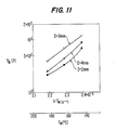
- the constants A,B may be obtained graphically from a line expressing a direct proportion between the apparent average viscosity ⁇ b and 1/T as apparent from Figs. 11 or 12.
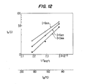
- a relationship between the individual temperature T M and an apparent gelation time t e for each pipe diameter D is illustrated in Fig. 12 and, as noted above, a substantially linear relationship is obtained between log t e and 1/T M with any selected pipe diameter D. If it is assumed that experiments of an ideal isothermal condition could also be conducted here, then the apparent gelation time t e represents a value peculiar or unique to the molding resin of an isothermal viscosity curve at a given temperature.
- FIG. 13 A relationship between the individual temperatures T M and a final flow distance l f for each pipe diameter D is graphically depicted in Fig. 13. As shown in Fig. 13, as the pipe diameter D decreases, the final flow distance l f decreases. This occurs because, although the decrease in viscosity occurs faster as the pipe diameter D decreases, the resistance value of the circular pipe flow passage 5 increases in proportion to the pipe diameter D to a fourth power and the flow rate is decreased in accordance with such increase of the resistance to thereby further decrease the gelation time.
- the final flow distance l f has a substantially proximate value at any individual temperature T M since the decrease in viscosity is rapid where the individual temperature T M is high, and while the flow distance t increases during the time, the flow stopping time comes quickly and a reverse phenomenon takes place where the individual temperature T M is low to contribute to the same degree of the characteristic values of the final flow distance t f .
- the value of apparent average viscosity ⁇ b is a characteristic value unique or peculiar to the molding resin which represents an initial viscosity of a viscosity curve at the individual temperature T M .
- the constants A,B may be obtained graphically from a line expressing a direct proportion between the apparent average viscosity ⁇ b and 1/T as apparent from Figs. 11 or 12.
- a relationship between the individual temperature T M and an apparent gelation time t e for each pipe diameter D is illustrated in Fig. 12 and, as noted above, a substantially linear relationship is obtained between log t e and 1/T M with any selected pipe diameter D. If it is assumed that experiments of an ideal isothermal condition could also be conducted here, then the apparent gelation time t e represents a value peculiar or unique to the molding resin of an isothermal viscosity curve at a given temperature.
- FIG. 13 A relationship between the individual temperatures T M and a final flow distance l f for each pipe diameter D is graphically depicted in Fig. 13. As shown in Fig. 13, as the pipe diameter D decreases, the final flow distance l f decreases. This occurs because, although the decrease in viscosity occurs faster as the pipe diameter D decreases, the resistance value of the circular pipe flow passage 5 increases in proportion to the pipe diameter D to a fourth power and the flow rate is decreased in accordance with such increase of the resistance to thereby further decrease the gelation time.
- the final flow distance l f has a substantially proximate value at any individual temperature T M since the decrease in viscosity is rapid where the individual temperature T M is high, and while the flow distance t increases during the time, the flow stopping time comes quickly and a reverse phenomenon takes place where the individual temperature T M is low to contribute to the same degree of the characteristic values of the final flow distance t f .
- thermosetting molding resin an isothermal viscosity for a thermosetting molding resin
- Equation (4) may be simplified by taking the following equations into account:
- equations (5) and (6) are the same as equations (2) and (3), respectively, and a, b, d, e, f and g are parameters peculiar or unique to a molding resin.
- equation (4) satisfies the following boundary conditions:
- ⁇ 2 may be determined in accordance with the following equation:
- equations (20), (21) and (22) respectively represent equations of continuity. principles of conservation of momentum and energy.
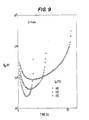
- equations (20) to (22) are solved by a numeral analysis method such as differential calculus of a finite element method under given initial and boundary conditions in combination with the isothermal viscosity equations (4) to (7) and the non-isothermal viscosity forecasting method equations (10) to (19), then a flow simulation in a circular pipe flow passage can be conducted with an outline of a simulation program using an input I, calculation C, an output 0 in accordance with the present invention being illustrated in Fig. 16. An average apparent viscosity may also be obtained as an output O and, consequently, comparison can then be made between calculated values of a result of the simulation program and actually measured values graphically illustrated in Figs. 8-10.
- a numeral analysis method such as differential calculus of a finite element method under given initial and boundary conditions in combination with the isothermal viscosity equations (4) to (7) and the non-isothermal viscosity forecasting method equations (10) to (19)
- a flow simulation in a circular pipe flow passage can be conducted
- the viscosity equations may, for example, take into account six parameters, namely, parameter a, b, d, e, f, and g in the relationships expressed in equations (5) to (7), and it is important to determine the values of these parameters sufficiently. Estimating values of the parameters a-g from data illustrated in Figs. 8-12 obtained by the device of the present invention is described more fully hereinbelow.
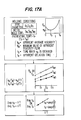
- a method of estimating values of the parameters a. b, d. and e is diagrammatically depicted in Fig. 17A.
- the method for estimating the values of the parameters a, b, d, and e is described hereinabove in connection with Figs. 11 and 12.
- Fig. 17A The values of the parameters a, b, d and e may be estimated from the following relationships which are graphically depicted in Fig. 17A:
- the dimensionless viscosities ⁇ a / ⁇ b are calculated at a dimensionless time when (t-t b )-/(t e -t b ) present fixed values (t b ⁇ t ⁇ t e ) in individual conditions.
- a relationship between the temperature T and ⁇ / ⁇ o may be graphically determined as illustrated in Fig. 17B where the value of tit o is constant.
- a flow simulation may be conducted using the values of the parameters a, b, d, e, f, and g estimated by the techniques outlined in Figs. 17A and 17B and thus calculated values and actually measured values of the apparent average viscosity ⁇ a are compared with each other.
- the values of the parameters a, b, d, e, f and g are finally corrected by a curve fitting method such as the method of least squares so that the calculated values may approach the actual measured values, and the values of the parameters are determined when an error which can be considered reasonable is reached.
- a curve fitting method such as the method of least squares
- Table 2 represent input data for a flow simulation in dependence upon the resin used.
- a comparison between measured values and calculated values by a simulation of the apparent average viscosity 1ja is graphically illustrated in Fig. 18.
- the measured value and calculated values by a simulation of the apparent average viscosity 1ja exhibit a very high conformity with respect to each other at each individual mold temperature, and the graphical illustration of Fig. 18 verifies the feasibility of the subject matter of the present invention.
- thermosetting resin which are not influenced by measurement conditions
- flow and curing parameters to a thermosetting resin which are not influenced by measurement conditions can reasonably be determined with a high degree of accuracy.
- a flow simulation is possible for any condition, and optimum dimensions of a flow passage of a metal mold for mass production and optimum molding conditions can be determined on the desk-type basis, that is, without an experimental production.
- a checking of a moldability in the development of a resin and lot management of a molding resin can also be greatly facilitated.
- Fig. 19 provides a schematic representation of an analyzing system for the estimation of a mode of flow of a resin within a metal mold, data necessary for simulation including physical properties of the resin, molding conditions and dimensions of the runner of the mold are supplied to an input means 100.
- the input means 100 provides a data output of the runner to a runner dividing means 103 and runner volume calculating means.
- the runner volume calculating means calculates an entire volume of the runner, with the runner dividing means dividing the runner into sections.
- the section volume calculating means 104 processes the output data of the runner dividing means 103 to determine a volume of each section, and a form resistance calculating means processes the same output data to determine a form resistance of each section.
- a cylindrical passage substituting means 106 processes the output data of the section volume calculating means to convert each section into a combination of cylindrical runners.
- Output data of the passage volume calculating means 101, output data of the section volume calculating means 104, and transfer time data from data of molding conditions supplied to the input means 100 are supplied to a section flow rate and section passage time calculating means 102.
- the section flow rate and section passage time calculating means 102 calculates the flow rate of the molding resin in each section and a second passage time at which the molding resin passes through predetermined sections.
- a flow simulating means 108 simulates the mode of flow of the molding resin through the cylindrical runners on the basis of the output data of the section flow rate and section passage time means 102, output of the cylindrical passage substituting means 106. and data of molding conditions supplied to the input means 100 to determine the temperature, viscosity, flow speed and mean or average apparent viscosity of the molding resin in each section of the runner.
- the results of the operation of the flow simulating means 108 is supplied to a viscosity comparing means 109.
- a viscosity comparing means 109 When the results of a comparison by the viscosity comparing means 109 are unsatisfactory, the simulation is interrupted and then an input condition changing means 107 alters or changes a portion of the input data supplied to the input means 100 and another cycle of simulation is initiated.
- a pressure loss calculating means 110 processes the data obtained through the simulation, namely, the mean apparent viscosity, the flow rate and form resistance for each section, to determine pressure loss in each section and overall pressure loss, namely. a sum of the pressure losses in all sections.
- the pressure loss calculating means 110 provides an output of the calculation to a pressure loss comparing means 111.
- the pressure loss comparing means 111 provides an output signal to the input condition changing means 107 to initiate another cycle of simulation.
- an output unit 112 provides a final data output including the dimensions of the runner, molding conditions and other necessary pertinent data.
- Figs. 20A-20D somewhat schematically illustrate different stages of a manufacturing process for a resin-sealed semiconductor device. More particularly, as shown in Fig. 20A, a plurality of semiconductor chips 32 are mounted on and connected on by gold leads 33 to a multiple lead frame 31 to form a plurality of semiconductor devices, with one of the semiconductor devices being more clearly illustrated in Fig. 20B.
- the multiple lead frames 31, each mounted with semiconductor chips 32 are placed ' in mold cavities 45 formed in a bottom half mold 44.
- an upper half mold 46 is brought into engagement with the bottom half mold 44 to secure the multiple lead frames 31 in the mold cavities 45.
- a pot 48 is charged with pellets of a thermosetting resin 47 preheated by a high frequency preheater (not shown).
- the thermosetting resin 47 is melted by heat transfer thereto from the metal mold heated by a heater 40, and then a plunger 49 of a molding machine (not shown) is forced downwardly to inject to molten resin 47 through runners 41 and gates 42 into the mold cavities 45.
- the molten resin 47 solidifies. Then, the upper half mold 46 is separated from the lower half mold 44 to eject resin-sealed devices such as shown in Fig. 20D.
- thermosetting resin 47 must be introduced into the cavities 45 at equal charging rates.
- a thermosetting resin 47 may be distributed uniformly to a plurality of mold cavities 45 by determining the dimensions of the runners 41 on the basis of an estimated pressure loss in the runners 41 so that the sums of each pressure loss in the runner 41 and pressure loss in a gate 42 corresponding to each mold cavity 45 are the same.
- the runners 41 and gates 42 of Fig. 20B each have a cross-section with the shape of a semi-circle or inverted trapezoid and, in most cases, the sectional area of each runner 41 varies with the length of the same.
- thermosetting resin 7 employing the foregoing complicated boundary conditions requires an enormous calculating time and, consequently, such a manner of simulation is not applicable to a practical design operation. Accordingly, in order to simplify the calculation for simulation, the present invention utilizes the simulation procedure discussed more fully hereinbelow.
- the runner 41 is divided into a plurality of sections, with a specific form resistance ⁇ of each section and flow rate Q in the same being calculated.
- Each section is substituted by a cylindrical passage, and a flow of resin through the cylindrical passage is simulated to calculate the temperature, viscosity, flow velocity and mean apparent viscosity ⁇ a , with the pressure loss AP being calculated by the following equation:
- Fig. 21 A provides an illustrative example of a section varying in sectional area from one end thereof to the other.
- X represents a distance of a section from a reference point, with X, and X 2 respectively representing a starting end and terminal end of the section, and W representing the width of the passage, with h being a depth of the passage.
- the width W and the depth h are functions, respectively of the distance X.
- the value of can be determined through analytical approximation of approximate integration using Simpson's rule or the like by representing the width W, the depth h and the factor F, respectively, by functions of X and, when W ⁇ h, the following relationship is valid:
- Fig. 21 B provides a representation of a cylindrical passage equivalent to the section shown in Fig. 21 A.
- the section between X, and X 2 represents a cylindrical passage having a uniform diameter, with the diameter of the cylindrical passage being determined so that the section illustrated in Fig. 21 A and cylindrical passage of Fig. 21 B have the same volume.
- cylindrical passages equivalent to the sections before and after the section shown in Fig. 21A of the runner tapering in a direction of flow of the resin are indicated by phantom lines.
- the flow rate Q in each section is calculated by calculating or determining Qp and dividing Qp by the number of branches, with Qp being determined in accordance with the following relationship:
- a pressure loss in each section of the runner 41 is determined and the overall pressure loss APT is determined by summing up or totalling the pressure losses in all sections.
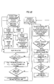
- Fig. 22 provides an example of a flow chart of procedure for designing runners 41 and gates 42 for a metal mold having a plurality of mold cavities 45 as shown in Fig. 20A so that the thermosetting resin is introduced into the mold cavities 45 at equal charging rates.
- first input data including physical properties of the thermosetting resin 7 such as shown in Table 2, molding conditions and dimensions of the metal mold are given.
- the molding conditions include the resin injecting time tp of the plunger 49, maximum injection pressure P M of the molding machine, a resin preheating temperature, and the temperature of the metal mold.
- the dimensions of the metal mold includes fixed values such as pitch of the mold cavities 45 and the layout of the runners 41, as well as temporary values for the rest of the dimensions.
- the overall volume V f of the runners 41 is calculated and each runner is divided into sections so that the number of junction planes between adjacent sections is at least equal to the number of branches branching from the runner 41 and the flow of thermosetting resin 7 is not branched in the sections. Then the volume V N and form resistance ⁇ N of each section are calculated.
- thermosetting resin 47 and the cylindrical passages are simulated sequentially in order of the cylindrical passages with respect to the direction of flow of the thermosetting resin 7 to calculate the temperature, viscosity ⁇ , flow velocity distribution and mean or average apparent viscosity ⁇ a of the thermosetting resin 47 in each section.
- the viscosity ⁇ of the thermosetting resin 47 before a predetermined radial position and the viscosity of the thermosetting resin 47 after the radial position in each section are compared to determine if the latter viscosity ⁇ is higher than the former viscosity. If the viscosity after the predetermined radial position is higher than the viscosity before the predetermined radial position, the molding conditions and dimensions of the metal mold are changed. and then the same calculations are repeated.
- thermosetting resin 47 The above adverse variation of the viscosity ⁇ of the thermosetting resin 47 is due to the excessively advanced hardening reaction of the thermosetting resin 47 prior to flowing into the mold cavities 45, and the supply of such inexcessively hardened thermosetting resin 47 having a high viscosity into the molding cavities 45 is highly likely to produce faulty moldings.
- a pressure loss ⁇ P R n in each section of the runner 41 is calculated in accordance with the following relationship:
- the calculated pressure loss ⁇ P RT is compared with a reference pressure loss AP RT is compared with a reference pressure loss ⁇ P RS and, when ⁇ P RS ⁇ AP RT , at least one of the data representing the dimensions of the runner 41 of the metal mold, the resin injecting time of the plunger 49, the resin preheating temperature and temperature of the metal mold is changed and the pressure loss ⁇ P RT is once again calculated on the basis of the new data.
- a form resistance ⁇ Gn to be given for each gate is calculated by substituting the value ⁇ P Gn , the value of average apparent viscosity ⁇ aG for each gate 42 obtained through the simulation of the flow of the thermosetting resin 47 and the value of the flow rate Q G n through each gate 42 into the following expression:
- the dimensions of the gates 42 are calculated by utilizing the equations (21) and (22). If the calculated dimensions of the gates 42 do not meet restrictive conditions for the respective gates 42, such as, for example, the upper and lower limits of an angle for a portion tapering in a direction of flow of the thermosetting resin 47 and the upper and lower limits of depth for the same portion, some of the dimensions of the metal mold and molding conditions are changed to obtain dimensions for the gates 42 meeting the restrictive conditions.
- Figs. 23A-23D respectively illustrate the relationship between the runner 41 and gates 42 of Fig. 20B constructed in accordance with the present invention.
- the pot 48, portion of the runner 41 radially extending from the pot 48, and the cavities 45 shown in Fig. 20B are admitted for the sake of clarity.
- a depth of the runner 11 is decreased gradually toward the extremity thereof so that the molten thermosetting resin reaches the cavities Ci, C 2 , C 3 , C 4 , Cs with the least time difference between the cavities.
- the gates 42 are formed so that the restriction angle 0s of the gate 42 near to the extremity of the runner 41 is greater than the restriction angle 8 1 of the gate 42 farther from the extremity of the runner 41 so as to equalize the sums of each of the pressure losses in a portion of the runner 42 reaching each cavity and in the gate 42 for the same cavity. If, for some practical reasons, there are restrictive conditions of the restriction angles ⁇ 1 , 0 2 , the pressure loss in the gate 42 may be adjusted by changing a width and / or depth of a gate outlet 43 of the respective gates 42.
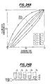
- Fig. 24A, 24B, 25A, 25B, 26, and 27 graphically and schematically explaining the process of filling cavities C 1 , C 2 , C 3 , C 4 , Cs of a metal mold having a construction similar to that shown in Figs. 23A and 23B and constructed without simulation by a conventional approach or method of processing the thermosetting resin 47.
- a dimensionless filling ratio is measureable along the ordinate, with a dimensionless filling time, namely, a time elapsed from a start of flow of the thermosetting resin 47 into a respective cavity C 1 , C 2 , C 3 , C 4 , Cs being measureable along the abscissa.
- the dotted line in Fig. 24A represents an ideal filling mode in which the cavities C 1 -C 5 are charged simultaneously with the thermosetting resin 47 at equal charging rates.
- Fig. 24B illustrates a state of the cavities C 1 -C 5 at a time 0.5 in Fig. 24A and, as evident from Figs. 24A and 24B, the actual filling mode deviates greatly from the ideal filling mode curve shown in Fig. 24A, and the charging rate for the upper cavities C,-C 3 is greater than the charging rate for the lower cavities Ca, C s .
- Figs. 25A and 25B graphically and schematically illustrate the process of filling the cavities C 1 , C 2 , C 3 , C 4 , Cs of a metal mold in accordance with the design method of the present invention on the basis of data obtained through the simulation of flow of the thermosetting resin 47 with a particular thermosetting resin.
- Fig. 25B represents the state of the cavities C 1 , C 5 at a time of 0.5 in Fig. 25A. As evident from Figs. 25A and 25B all of the cavities Ci-Cs are charged with the thermosetting resin 47 in filling modes very close to the ideal filling mode represented by the ideal curve in Fig. 25A and at substantially equal charging rates.
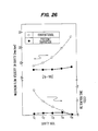
- Fig. 26 provides a graphical illustration of a maximum flow velocity of the thermosetting resin 47 in each cavity Ci-C s , and resin retention time, namely, a time period between a completion of the filling of the respective cavities Ci-Cs with the thermosetting resin 47 and a completion of the injection operation of the plunger 49.
- the resin injection time is represented by tp.
- the flow velocity is greater for the lower cavities than for the upper cavities due to the increase in the flow rate for the lower cavities every time the upper cavity is filled with the thermosetting resin and the retention. time is greater for the upper cavities are charged with the thermosetting resin 47 in the manner shown in Figs. 24A and 24B.
- Fig. 27 provides a graphical illustration of the percent defects of resin-filled devices in terms of gold lead distortion.
- a diameter D A of the gold leads A is greater than the diameter D B of the gold leads B.
- None of the gold leads A of the device is sealed with the resin using the metal mold constructed by conventional techniques and the device is sealed with a resin utilizing a metal mold designed and constructed in accordance with the present invention are distorted.
- the percent defective of the gold leads B of devices sealed with the resin by utilizing a metal mold designed by a conventional design method is greater for devices resin-sealed in lower cavities, which indicates that the distortion of the thin gold leads B increases with the increase in flow of the velocity of the resin. Since the flow velocities of the resin in all of the cavities of the metal mold constructed in accordance with the present invention are the same and constant, even the thin gold leads B are not distorted.
- Table 3 summarizes the percent defective in terms of external appearance of resin-sealed devices comparing conventional design methods and the method contemplated by the present invention.
Landscapes
- Health & Medical Sciences (AREA)
- Life Sciences & Earth Sciences (AREA)
- Chemical & Material Sciences (AREA)
- Engineering & Computer Science (AREA)
- Food Science & Technology (AREA)
- Medicinal Chemistry (AREA)
- Physics & Mathematics (AREA)
- Analytical Chemistry (AREA)
- Biochemistry (AREA)
- General Health & Medical Sciences (AREA)
- General Physics & Mathematics (AREA)
- Immunology (AREA)
- Pathology (AREA)
- Manufacturing & Machinery (AREA)
- Mechanical Engineering (AREA)
- Injection Moulding Of Plastics Or The Like (AREA)
- Moulds For Moulding Plastics Or The Like (AREA)
Abstract
Description
- accuracy as well as a metal mold and method of designing or constructing a runner of a metal mold using the flow and curve characteristics of the molding resin.
- In accordance with advantageous features of the present invention, changes in the viscosity under several metal mold temperature conditions using several metal molds having flow passage which have uniform sectional dimensions along a flow direction of the resin are actually measured by an automatic measuring device, where the pressure loss, flow distance, flow rate, average apparent viscosity, etc., of the molding resin and the flow passages are calculated and outputted and evaluated so as to determine optimum constructional features or characteristics of a metal mold.
- Moreover, according to the present invention, values of parameters are estimated in isothermal viscosity equations for flow simulation from characteristics values of the thermosetting resin by an extrapolation method, with the values being inputted and a flow simulation being conducted under the same conditions as experimentally carried out. The actual measured values and the calculated values of change in viscosity are compared with each other and the values of the parameters are successively corrected, with the values of the parameters being determined when the corrected values of the parameters come into a predetermined range of error.
- By virtue of the measuring device and method of the present invention, values of parameters unique or peculiar to a molding resin which are not influenced by molding conditions can be determined with a high degree of accuracy, and, by conducting a flow simulation with a metal mold having a flow passage of arbitrary dimensions using the values of the parameters, a forecasting of the flow in an actual metal mold is possible, with a selection of optimal molding conditions and metal mold flow passage dimensions being readily determined in advance so as to facilitate a designing of a metal mold in a minimal amount of time and at a substantial reduction in cost.
- In accordance with still further features of the present invention, an estimation of the flow of a thermosetting resin within a metal mold is accomplished by dividing the runner of the metal mold into a plurality of sections, calculating specific form resistance and flow rate Q for each section of the runner, and simulating the flow of the thermosetting resin in each section of the runner on an assumption that a shape of the section of the runner is cylindrical. The temperature, viscosity, flow speed, and mean apparent viscosity na of the molding resin in each section is calculated and a pressure loss is determined on the basis of the. relationship AP = p'na'Q.
- In accordance with the method of the present invention, it is possible to strictly determine the specific form resistance and flow rate of a runner to calculate pressure loss necessary for an optimum runne.r design. Moreover, since the runner of a practical or actual metal mold normally requiring a complicated flow analysis and a considerable analysis time can be obtained by analyzing a combination of cylindrical passages, and the mean apparent viscosity in each cylindrical passage is calculated in the present invention, a flow analysis can be completed with a very short calculating time and the pressure loss can be estimated with a sufficiently high accuracy.
- Additionally, by virtue of the novel features of the present invention, it is possible to remarkably reduce the time necessary for the development of a product as well as to improve the quality of the product by determining optimum dimensions of a metal mold and molding conditions through quick and highly accurate simulation of the mold of flow of a molding resin within the metal mold.
- In accordance with the present invention, a device for measuring flow in curing characteristics of a resin is provided which includes a metal mold having a pot and a flow passage connected to the pot, with a plunger for injecting resin supplied to the pot into a flow passage. A resin pressure detector is provided in the metal mold, with a displacement detector being provided for detecting a position of the plunger. Data processing means are provided for storing and arranging signals from the resin pressure detector and the displacement detector, with a calculating means executing a physical quantity conversion of the processed signals and a calculation in combination of a physical quantity and constant calculated from various dimensions of flow passages of the metal mold. An outputting means is provided for enabling an outputting of a result of the calculation from the calculating means.
- For the purposes of measuring the flow and curing characteristics of a thermosetting resin, in accordance with the present invention, the metal mold is provided with a single runner connecting the pot and a single flow passage connected to an end of the runner at an end opposite of the pot. The single flow passage is provided with cross-sectional dimensions with a uniform along a flow direction of the resin, and the sectional area of the flow passage is less than the sectional area of the runner. Advantageously, the cross-sectional shape of the flow passage of the metal mold is a circle, with a shape of the flow passage of the metal mold in a flow direction of the thermosetting resin being helical or spiral.
- Advantageously, the pressure detector means is mounted on a wall of the runner of the metal mold, and the metal mold is constructed so that the flow passage section is capable of being separated from the accuracy as well as a metal mold and method of designing or constructing a runner of a metal mold using the flow and curve characteristics of the molding resin.
- In accordance with advantageous features of the present invention, changes in the viscosity under several metal mold temperature conditions using several metal molds having flow passage which have uniform sectional dimensions along a flow direction of the resin are actually measured by an automatic measuring device, where the pressure loss, flow distance, flow rate, average apparent viscosity, etc., of the molding resin and the flow passages are calculated and outputted and evaluated so as to determine optimum constructional features or characteristics of a metal mold.
- Moreover, according to the present invention, values of parameters are estimated in isothermal viscosity equations for flow simulation from characteristics values of the thermosetting resin by an extrapolation method, with the values being inputted and a flow simulation being conducted under the same conditions as experimentally carried out. The actual measured values and the calculated values of change in viscosity are compared with each other and the values of the parameters are successively corrected, with the values of the parameters being determined when the corrected values of the parameters come into a predetermined range of error.
- By virtue of the measuring device and method of the present invention, values of parameters unique or peculiar to a molding resin which are not influenced by molding conditions can be determined with a high degree of accuracy, and, by conducting a flow simulation with a metal mold having a flow passage of arbitrary dimensions using the values of the parameters, a forecasting of the flow in an actual metal mold is possible, with a selection of optimal molding conditions and metal mold flow passage dimensions being readily determined in advance so as to facilitate a designing of a metal mold in a minimal amount of time and at a substantial reduction in cost.
- In accordance with still further features of the present invention, an estimation of the flow of a thermosetting resin within a metal mold is accomplished by dividing the runner of the metal mold into a plurality of sections, calculating specific form resistance and flow rate Q for each section of the runner, and simulating the flow of the thermosetting resin in each section of the runner on an assumption that a shape of the section of the runner is cylindrical. The temperature, viscosity, flow speed, and mean apparent viscosity na of the molding resin in each section is calculated and a pressure loss is determined on the basis of the. relationship AP = p'na'Q.
- In accordance with the method of the present invention, it is possible to strictly determine the specific form resistance and flow rate of a runner to calculate pressure loss necessary for an optimum runne.r design. Moreover, since the runner of a practical or actual metal mold normally requiring a complicated flow analysis and a considerable analysis time can be obtained by analyzing a combination of cylindrical passages, and the mean apparent viscosity in each cylindrical passage is calculated in the present invention, a flow analysis can be completed with a very short calculating time and the pressure loss can be estimated with a sufficiently high accuracy.
- Additionally, by virtue of the novel features of the present invention, it is possible to remarkably reduce the time necessary for the development of a product as well as to improve the quality of the product by determining optimum dimensions of a metal mold and molding conditions through quick and highly accurate simulation of the mold of flow of a molding resin within the metal mold.
- In accordance with the present invention, a device for measuring flow in curing characteristics of a resin is provided which includes a metal mold having a pot and a flow passage connected to the pot, with a plunger for injecting resin supplied to the pot into a flow passage. A resin pressure detector is provided in the metal mold, with a displacement detector being provided for detecting a position of the plunger. Data processing means are provided for storing and arranging signals from the resin pressure detector and the displacement detector, with a calculating means executing a physical quantity conversion of the processed signals and a calculation in combination of a physical quantity and constant calculated from various dimensions of flow passages of the metal mold. An outputting means is provided for enabling an outputting of a result of the calculation from the calculating means.
- For the purposes of measuring the flow and curing characteristics of a thermosetting resin, in accordance with the present invention, the metal mold is provided with a single runner connecting the pot and a single flow passage connected to an end of the runner at an end opposite of the pot. The single flow passage is provided with cross-sectional dimensions with a uniform along a flow direction of the resin, and the sectional area of the flow passage is less than the sectional area of the runner. Advantageously, the cross-sectional shape of the flow passage of the metal mold is a circle, with a shape of the flow passage of the metal mold in a flow direction of the thermosetting resin being helical or spiral.
- Advantageously, the pressure detector means is mounted on a wall of the runner of the metal mold, and the metal mold is constructed so that the flow passage section is capable of being separated from the runner section.
- In order to determine or judge when the thermosetting resin begins to flow into the flow passage and to terminate a measurement of the flow, according to the present invention, two pressure levels for comparative purposes are provided with a signal of the pressure detector being set. Upon exceeding the first pressure level, it is determined that the thermosetting resin has begun to flow and, upon exceeding the second pressure level, the flow measurement is terminated.
- According to the present invention, a difference between adjacent signals of the displacement detector is calculated and, when such difference is lower than a predetermined level and the signal of the pressure detector exceeds the preset second pressure level, the measurement of the flow of the thermosetting resin is ended.
- In accordance with still further features of the present invention, a changing rate of pressure data relative to time is retroactively determined from a point of time at which the measurement of the flow of the thermosetting resin is ended or terminated, and the point of time at which the value of the changing rate becomes smaller than a predetermined value is regarded as a flow stopping point of time.
- To estimate a pressure loss within a metal mold in order to obtain data for designing or constructing a metallic mold having a pot and runner extending from the pot, in accordance with the present invention, a volume of the runners is calculated on the basis of predetermined dimensions of the runner, with a thermosetting resin injecting time being set in which a plunger injects the thermosetting resin introduced into the pot into the runners. The flow rate of the thermosetting resin injected into the runners is calculated. and the flow rate is divided by the number of branches formed by the runners. The flow rate of the thermosetting resin is calculated at an optional position in the runner, and the runner is divided into a plurality of sections by planes extending perpendicular to a flow direction of the thermosetting resin. A form resistance of the runner for each section of the runner is calculated on the basis of a width, depth, cross-sectional shape and length of the runner, and each section of the runner is simulated by an equivalent cylindrical passage. Basic equations expressing a variable-viscosity transportation phenomenon of the thermosetting resin in each cylindrical passage are solved by utilizing initial and boundary conditions, and the temperature, viscosity, flow velocity, and mean apparent viscosity of the resin in each cylindrical passage is calculated. A calculating pressure loss in each section is determined in accordance with a relationship of the form resistance, mean apparent viscosity, and flow rate of the thermosetting resin at the optional position in the runner, and the pressure losses for all of the sections of the runner are summed up or totalled to obtain an overall pressure loss.
- According to the present invention, the calculated overall pressure loss is compared with a predetermined reference pressure loss and the overall pressure loss as calculated by changing a value of at least one of dimensions of the runner, injection time, temperature of the metal mold, and resin preheating temperature when the predetermined reference pressure loss is less than or equal to the calculated overall pressure loss, with the conditions being sequentially varied until values of the dimensions of the runner and molding conditions satisfy an inequality wherein the predetermined pressure reference loss is greater than the calculated overall pressure loss.
- The dimensions of the runner and molding conditions according to the present invention are determined so that the predetermined reference pressure loss is greater than the calculated overall pressure loss, and the viscosity of the thermosetting resin before a predetermined radial position is not greater than the viscosity after the predetermined radial position.
- With a metal mold having a pot, a runner extending from the pot, and a plurality of mold cavities arranged along the runner and respectively communicating with the runner by gate means, the number of joining planes of the sections corresponds at least to the number of branches branching from the runner, with the dimensions of the gate means for each mold cavity being determined in accordance with the present invention so that the sum of pressure losses in the runner and the gate means is the same for all mold cavities in order that the flow rate is equally distributed to all of the mold cavities.
- A circular or spiral pipe flow passage connected to the runner in accordance with the present invention has a smaller cross-sectional area than the cross-sectional area of the runner, with the pressure detector detecting the pressure of the resin which flows into the circular or spiral pipe flow passage from the runner. The data processing means which inputs a signal from the pressure detector and the plunger displacement detector calculates an average apparent viscosity on the basis of predetermined values of the mold and the signals from the displacement and the pressure detector.
- In constructing the runner of a mold utilizing the unique or peculiar flow and curing characteristics of the particular resin, according to the present invention, the resin material values unique or peculiar to flow and curing characteristics of the thermosetting resin, molding conditions, and dimensions of the mold are obtained. The runners are divided into a plurality of sections and a specific form resistance for each section and flow rate in the sections of the runner is calculated. Each section of the runner is substituted by a cylindrical passage and a pressure loss and viscosity at each section is calculated on the basis of an isothermal viscosity relationship, a non-isothermal viscosity relationship, a continuant relationship, as well as a relationship of momentum and conservation of energy. A pressure loss in the runner and viscosity are compared with a predetermined value, and a dimension of the mold on the basis of such comparison is determined.
- The above and other objects, features, and advantages of the present invention will become more apparent from the following description when taken in connection with the accompanying drawings which show, for the purpose of illustration only, several embodiments in accordance with the present invention.
-
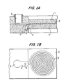
- Fig. 1 A is a vertical cross-sectional partial view of a metal mold constructed in accordance with the present invention:
- Fig. 1 B is a partial top plan view of a female portion of the metal mold of Fig. 1 A;
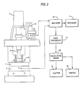
- Fig. 2 is a schematic view of a transfer molding machine and control therefor constructed in accordance with the present invention;
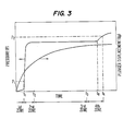
- Fig. 3 is a graphical illustration of data determined in dependence upon values indicated by a recorder of a measuring device of the present invention;
- Fig. 4 is a flow chart for automatic data fetching;
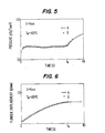
- Fig. 5 is a graphical illustration of pressure data;
- Fig. 6 is a graphical illustration of injection plunger displacement data;
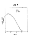
- Fig. 7 is a graphical illustration of injection plunger velocity data;
- Figs. 8-10 are graphical illustrations of changes of an average apparent viscosity with various pipe diameters;
- Fig. 11 is a graphical illustration of a relationship between a minimum value of an average apparent viscosity and a temperature of a metal mold;
- Fig. 12 is a graphical illustration of a relationship between an apparent gelation time and temperature of the metal mold;
- Fig. 13 is a graphical illustration of a relationship between a final flow distance and temperature of a metal mold;
- Fig. 14 is a characteristic view of an isothermal viscosity equation model;
- Fig. 15 is a graphical illustration of data for calculating a viscosity change in a non-isothermal condition;
- Fig. 16 is a general flow chart of a molding resin flow simulation;
- Figs. 17A and 17B are flow charts explaining an estimation of flow and curing parameters of a molding resin;
- Fig. 18 is a graphical comparative illustration between measured values and calculated values of an average apparent viscosity;
- Fig. 19 is a schematic illustration of an analysis system constructed in accordance with the present invention;
- Fig. 20A is a plan view of a multiple lead frame of a semiconductor device;
- Fig. 20B is an enlarged detailed view of a portion of the semiconductor device of Fig. 20A;
- Fig. 20C is a schematic representation of a process of sealing the semiconductor devices of Fig. 20A in a resin;
- Fig. 20D is a perspective view of resin sealed semiconductor devices obtained from the process of Fig. 20C;
- Fig. 20E is a perspective view of an individual resin sealed semiconductor device obtained in accordance with the present invention;
- Figs. 21A and 21 B are schematic illustrations for depicting a method of calculating pressure loss in a runner of a metal mold;
- Fig. 22 is a flow chart depicting a procedure for designing and constructing runners and gates of a metal mold provided with a plurality of mold cavities;
- Figs. 23A, 23B and 23C are schematic views of runners and gates of a metal mold;
- Fig. 24A is a graphical illustration of a relationship between charging time and filling ratio of a metal mold in accordance with a conventional method;
- Fig. 24B is a schematic view of a charging of cavities of a metal mold with a molding resin in accordance with a conventional method;
- Fig. 25A is a graphical illustration of a relationship between charging time and filling ratio of a metal mold in accordance with the present invention;
- Fig. 25B is a schematic view of a mode of charging cavities of a metal mold in accordance with the present invention;
- Fig. 26 is a graphical illustration of a maximum flow velocity of a molding resin in cavities and retention time for the cavities: and
- Fig. 27 is a graphical illustration of a defect percent of gold leaves in terms of distortion of the gold leaves.
- Referring now to the drawings wherein like reference numerals are used throughout the various views to designate like parts and. more particularly, to Figs. 1 A and 1 B. according to these figures, a metal mold generally designated by the reference character M includes a
male mold 1 and afemale mold 2, with themale mold 1 including apot 3 for receiving molding resin (not shown). The molding resin from thepot 3 passes through arunner 4 having a large cross-sectional area and flows into a spiral circularpipe flow passage 5. The metal mold M enables a determination in a change in viscosity of the molding resin within the circularpipe flow passage 5 and is constructed such that a loss in pressure is measured by apressure detector 6, of a conventional construction, mounted on a wall of therunner 4. - The cross-sectional area of the
runner 4 is greater than a cross-sectional area of the circularpipe flow passage 5 in order to reduce a thermal history or heat the molding resin absorbs from themetal mold 1 up to an isothermal condition until the molding resin enters the circularpipe flow passage 5, and in order to reduce a loss of the pressure in therunner 4 to enable a measurement of a point of time at which the flow of the molding resin in the circularpipe flow passage 5 begins, as well as a loss of pressure during a flow of the molding resin in the circularpipe flow passage 5 by thepressure detector 6 detecting a sudden rise in the pressure at the instant when an end of flow of the molding resin enters the circularpipe flow passage 5 having a smaller cross-sectional area. To enable a selection of an arbitrarycircular flow passage 5, the metal mold M includes removable mold blocks receivable in the male andfemale molds pipe flow passage 5. - Table 1 provides an exemplary listing of sectional areas of
circular flow passages 5 for the purposes of discussing the subject matter of the present invention; however, as can readily be appreciated, the diameters listed for the circularpipe flow passage 5 are merely examples and other diameters D can also be considered.
- The sectional areas listed in Table 1 were selected since such areas have substantially proximate values to those of flow passages of metal molds which may be employed at an encapsulating step for electronic components. The
runner 4 of Figs. 1A and 1B has a sectional area of about ten times a sectional area of flow passage No. 3 in Table 1. It is noted that, in accordance with the present invention, the molding resin used is an epoxy molding material for application to encapsulation of electronic parts, and the molding resin material will not flow to a terminal end of the circularpipe flow passage 5 but will stop flowing at a portion intermediate of the end of the circularspiral flow passage 5 due to a curing reaction. - As shown in Fig. 2, a
transfer molding machine 7 includes a reciprocal plunger 8 adapted to be moved in a downward direction to feed molding resin material into the metal mold M. A displacement of the plunger 8 is detected by a conventional displacement detector 9 mounted on themolding machine 6, with an output signal indicative of the displacement of the plunger 8 being supplied to a conventional recorder means 11 and a conventional data processing means 12 by an amplifier means 10. An output signal of the pressure detected by thepressure detector 6, mounted on, for example, a wall of a runner of thefemale mold 2, is also supplied to the recorder means 11 and data processing means 12 by the amplifier means 10. The data processing means 12 includes a controlling microcomputer and various modules in combination and is adapted to execute storing and data arraying processes in a conventional manner. - Data processed by the data processing means 12 are subsequently transmitted or supplied to a conventional calculating means 13 in which calculations for physical quantity conversion of signals and calculations of characteristic values are executed. Finally, an output signal from the calculating means 13 is supplied to a plotter means 14 and/or printer means 15 so as to enable the results of the detection of the displacement of the plunger 8 by the detector 9 and detection of pressure by the
pressure detector 6. - Fig. 3 provides a graphical example of values indicated or provided by the recorder means 11 when the molding resin material is caused to flow in the metal mold M. In Fig. 3, the reference character t, denotes a point of time at which a leading end of the flow of molding resin enters the circular
pipe flow passage 5, and the sudden rise in the pressure P detected by thepressure detector 6 in a short period of time before and after the point of time t1. After the point of time ti , the pressure P exhibits a substantially fixed value and, after another point in time ta at which the flow of molding resin is stopped, a pressure rise resulting from a thermal expansion component once again takes place. Meanwhile, the change of the displacement ℓp of the plunger 8 has a tendency to decrease as the time passes. - More particularly, intervals of time for sampling of data were changed for individual zones such that the interval was short where the change in pressure was increased but the interval was long where the change in pressure was small. In Fig. 3, the 1 st zone is provided to discriminate a point of time t, at which a leading end of the flow of the molding resin reaches the circular
pipe flow passage 5, and a point of time after a preset pressure P1 was exceeded was regarded as a point of time at which a flow of the molding resin in the circularpipe flow passage 5 was commenced. Meanwhile in the 2nd zone, a sampling is performed to a preset point in time t2 in a region wherein the pressure change is still great. In the 3rd zone, sampling in a fixed pressure region to a point in time t3 is carried out. The 4th zone is provided to enable a making of a judgment of a point of time t4 at which the flow of the molding resin is stopped and in order to complete the measurement with certainty. The measurement was ended at the point of time t4 when the two requirements were simultaneously met, namely, that the difference between adjacent data of the displacement tp of the plunger 8 is smaller or less than a predetermined value and the pressure is higher than a preset pressure P2. - Fig. 4 provides a flow chart for determining a measurement end. As shown in Fig. 4, automatic discrimination of the point of time ta proceeds such that, making use of a difference between a pressure changing ratio during the flow of the molding resin and a pressure changing ratio after a stopping of the flow of the molding resin, changing ratios may be successfully determined by linear approximation from adjacent data retroactively from the point of time at which the measurement was ended, and a point of time when the changing ratio was smaller than a predetermined value was regarded as the point of time ta.
- In Fig. 5, values of the pressure P were automatic measurements and calculations were executed by the above-described method are shown at B, with A representing values indicated by the recorder means 11. As apparent from Fig. 5, the automatic measurements and calculations of the values represented by Ad and e = parameters peculiar or unique to the molding resin regarding the gelatin time to.

- A relationship between the individual temperatures TM and a final flow distance ℓf for each pipe diameter D is graphically depicted in Fig. 13. As shown in Fig. 13, as the pipe diameter D decreases, the final flow distance if decreases. This occurs because, although the decrease in viscosity occurs faster as the pipe diameter D decreases, the resistance value of the circular
pipe flow passage 5 increases in proportion to the pipe diameter D to a fourth power and the flow rate is decreased in accordance with such increase of the resistance to thereby further decrease the gelation time. - Meanwhile, where the pipe diameter D is identical, the final flow distance tf has a substantially proximate value at any individual temperature TM since the decrease in viscosity is rapid where the individual temperature TM is high, and while the flow distance ℓf increases during the time, the flow stopping time comes quickly and a reverse phenomenon takes place where the individual temperature TM is low to contribute to the same degree of the characteristic values of the final flow distance ℓf.
- In contradistinction to a widely-accepted, spiral flow test adopted by the Epoxy Molding Material Institute, a branch of the Society of Plastics Industry in the United States, for evaluation of a moldability of a thermosetting resin wherein only a value corresponding to the final flow distance if is determined, in of the circular
pipe flow passage 5 to the molding resin takes place in theflow passage 5, and at an initial stage of such flow, the apparent average viscosityη a is decreased due to melting. - If it is assumed that an ideal isothermal condition is obtained wherein the temperature of the molding resin becomes equal to a temperature of the metal mold M at an instant when the molding resin flows into the circular
pipe flow passage 5 and, consequently, there is no influence of a thermal history until that time, then the value of apparent average viscosityη b is a characteristic value unique or peculiar to the molding resin which represents an initial viscosity of a viscosity curve at the individual temperature TM. - Where the data of Fig. 11 involves a very small influence on a rise of viscosity by a curing reaction of the molding resin, if the apparent average viscosity
η b where the pipe diameter D = 0 mm., or, in other words, where the temperature of the metal mold M can be regarded as the temperature of the molding resin, is determined for each individual temperature TM by an extrapolation method, then it is considered that this is near to a relationship between an initial viscosity unique or peculiar to the molding resin and the individual temperature TM. A relationship suggested in 1934 by E. N. doc Andrade between liquid viscosity M and absolute temperature T may be expressed as follows: - 77 = A'exp (B/T) = A'exp (E/RT), where:
- A & B = a constant,
- E = apparent activation energy, and
- R = gas constant.
- Taking the above relationship into account, it can be seen that the constants A,B may be obtained graphically from a line expressing a direct proportion between the apparent average viscosity
η b and 1/T as apparent from Figs. 11 or 12. - Applying the above relationship to resin flow and curing characteristics, it can be seen that the following relationship exists:
-
η o = a'exp (
- where:
- ηo = an initial viscosity;
- T = an absolute temperature; and
- a and b = parameters peculiar or unique to the molding resin regarding an initial viscosity.
- A relationship between the individual temperature TM and an apparent gelation time te for each pipe diameter D is illustrated in Fig. 12 and, as noted above, a substantially linear relationship is obtained between log te and 1/TM with any selected pipe diameter D. If it is assumed that experiments of an ideal isothermal condition could also be conducted here, then the apparent gelation time te represents a value peculiar or unique to the molding resin of an isothermal viscosity curve at a given temperature. A relationship between a gelation time te and the individual temperature TM can approximately be obtained by determining a value when the pipe diameter D = 0 mm by an extrapolation method similar to the method for determining the apparent average viscosity
η a. Taking into account the above-noted relationship suggested by E. N. doc Andrade, the gelation time te and individual temperature TM, the relationship may be expressed in accordance with the following equation: - to = d exp (t ) (3)
- where:
- to = a gelation time;
- T = an absolute temperature; and
- d and e = parameters peculiar or unique to the molding resin regarding the gelatin time to.
- A relationship between the individual temperatures TM and a final flow distance ℓf for each pipe diameter D is graphically depicted in Fig. 13. As shown in Fig. 13, as the pipe diameter D decreases, the final flow distance ℓf decreases. This occurs because, although the decrease in viscosity occurs faster as the pipe diameter D decreases, the resistance value of the circular
pipe flow passage 5 increases in proportion to the pipe diameter D to a fourth power and the flow rate is decreased in accordance with such increase of the resistance to thereby further decrease the gelation time. - Meanwhile, where the pipe diameter D is identical, the final flow distance ℓf has a substantially proximate value at any individual temperature TM since the decrease in viscosity is rapid where the individual temperature TM is high, and while the flow distance t increases during the time, the flow stopping time comes quickly and a reverse phenomenon takes place where the individual temperature TM is low to contribute to the same degree of the characteristic values of the final flow distance tf.
- In contradistinction to a widely-accepted, spiral flow test adopted by the Epoxy Molding Material Institute, a branch of the Society of Plastics Industry in the United States, for evaluation of a moldability of a thermosetting resin wherein only a value corresponding to the final flow distance ti is determined, in of the circular
pipe flow passage 5 to the molding resin takes place in theflow passage 5, and at an initial stage of such flow, the apparent average viscosityη a is decreased due to melting. - If it is assumed that an ideal isothermal condition is obtained wherein the temperature of the molding resin becomes equal to a temperature of the metal mold M at an instant when the molding resin flows into the circular
pipe flow passage 5 and, consequently, there is no influence of a thermal history until that time, then the value of apparent average viscosity ηb is a characteristic value unique or peculiar to the molding resin which represents an initial viscosity of a viscosity curve at the individual temperature TM. - Where the data of Fig. 11 involves a very small influence on a rise of viscosity by a curing reaction of the molding resin, if the apparent average viscosity ηb where the pipe diameter D = 0 mm., or, in other words, where the temperature of the metal mold M can be regarded as the temperature of the molding resin, is determined for each individual temperature TM by an extrapolation method, then it is considered that this is near to a relationship between an initial viscosity unique or peculiar to the molding resin and the individual temperature TM. A relationship suggested in 1934 by E. N. doc Andrade between liquid viscosity M and absolute temperature T may be expressed as follows:
- 77 = A'exp (B/T) = A·exp(E/RT), where:
- A & B = a constant,
- E = apparent activation energy, and
- R = gas constant.
- Taking the above relationship into account, it can be seen that the constants A,B may be obtained graphically from a line expressing a direct proportion between the apparent average viscosity
η b and 1/T as apparent from Figs. 11 or 12. - Applying the above relationship to resin flow and curing characteristics, it can be seen that the following relationship exists:
-
η o = a·exp(
- where:
- ηo = an initial viscosity;
- T = an absolute temperature; and
- a and b = parameters peculiar or unique to the molding resin regarding an initial viscosity.
- A relationship between the individual temperature TM and an apparent gelation time te for each pipe diameter D is illustrated in Fig. 12 and, as noted above, a substantially linear relationship is obtained between log te and 1/TM with any selected pipe diameter D. If it is assumed that experiments of an ideal isothermal condition could also be conducted here, then the apparent gelation time te represents a value peculiar or unique to the molding resin of an isothermal viscosity curve at a given temperature. A relationship between a gelation time te and the individual temperature TM can approximately be obtained by determining a value when the pipe diameter D = 0 mm by an extrapolation method similar to the method for determining the apparent average viscosity
η a. Taking into account the above-noted relationship suggested by E. N. doc Andrade, the gelation time te and individual temperature TM, the relationship may be expressed in accordance with the following equation: - to = d exp (t ) (3)
- where:
- to = a gelation time;
- T = an absolute temperature; and
- d and e = parameters peculiar or unique to the molding resin regarding the gelatin time to.
- A relationship between the individual temperatures TM and a final flow distance ℓf for each pipe diameter D is graphically depicted in Fig. 13. As shown in Fig. 13, as the pipe diameter D decreases, the final flow distance ℓf decreases. This occurs because, although the decrease in viscosity occurs faster as the pipe diameter D decreases, the resistance value of the circular
pipe flow passage 5 increases in proportion to the pipe diameter D to a fourth power and the flow rate is decreased in accordance with such increase of the resistance to thereby further decrease the gelation time. - Meanwhile, where the pipe diameter D is identical, the final flow distance ℓf has a substantially proximate value at any individual temperature TM since the decrease in viscosity is rapid where the individual temperature TM is high, and while the flow distance t increases during the time, the flow stopping time comes quickly and a reverse phenomenon takes place where the individual temperature TM is low to contribute to the same degree of the characteristic values of the final flow distance tf.
- In contradistinction to a widely-accepted, spiral flow test adopted by the Epoxy Molding Material Institute, a branch of the Society of Plastics Industry in the United States, for evaluation of a moldability of a thermosetting resin wherein only a value corresponding to the final flow distance ti is determined, in accordance with the present invention, it is possible to determine the final flow distance ℓf by utilizing information regarding the unique or peculiar flowing and curing conditions of the molding resin.
- In order to rapidly and reasonably design or construct a flow passage of a metal mold and select molding conditions in an initial selection of a resin material to be used or in a particular production process, it is necessary to effect a flow simulation using characteristic values peculiar or unique to a molding resin obtained by the device of the present invention as input data, and such characteristic values can be determined in the following manner.
- At first, an isothermal viscosity for a thermosetting molding resin may be determined in accordance with the following equation:

- η = a viscosity;
- ηo = an initial viscosity;
- to = a gelation time;
- c = a viscosity increase coefficient:
- T = an absolute temperature; and
- t = a time period.
- Equation (4) may be simplified by taking the following equations into account:
- ηo(T) = a exp (b/T) (5)
- to(T) = d exp (e;T) (6)
- c(T) = f/T - g (7)
- As readily apparent, equations (5) and (6) are the same as equations (2) and (3), respectively, and a, b, d, e, f and g are parameters peculiar or unique to a molding resin.
- When the time period t in equation (4) is equal to 0, equation (4) satisfies the following boundary conditions:
- when t = 0,
- η = ηo (T) (8)
- when t = to(T),
- η = ∞ (9)
- The characteristics of equation (4) at an arbitrary temperature T are graphically depicted in Fig. 14.
- Since the molding resin flows in a metal mold M while receiving heat from a wall of the
pipe passage 5, in almost in all cases the molding resin is in a non-isothermal condition. A forecasting method of a viscosity in such an instance is described hereinbelow. At first, if the equation (4) is arranged dimensionlessly, then the following equation is obtained:
- µ = (η/ηo (T)) 1/C(T) (11)
- τ = t/to (T) (12)
- A curve when µ = 1 at τ = 0 and µ = ∞ at τ = 1 has the characteristics shown in Fig. 15.
- In Fig. 15 µ = µ1 at τ = τ1, and the time then is represented by t2, then a new viscosity will be calculated when the time passes in time increments At and the temperature also increases by temperature increments AT until the time and temperature reach t2 and T2 respectively. From equation (12) τ is a function of the time period t and the temperature T, and an increment Δτ or until a new condition τ2 may be calculated from the following equation:
- Δτ =


- The following equations can be obtained from equations (12) and (6):


- Since At and AT of equation (13) are known in advance as shown in Fig. 15, and At can be determined, by substituting T = T. into equation (14) and T = T, and τ = τ1 into equation (15), the following equation is obtained:
- τ2 = τ1 + Δτ (16)
- By substituting r = r2 into the equation (10), µ2 may be determined in accordance with the following equation:

- From equation (11) the following equation can be obtained:
- η2 = ηo (T)µc(T) (18)
- By substituting the values of T = T2 and µ = µ2 into equation (18), a new viscosity η2 at a new condition can be determined by the following equation:
- η2 = ηo (T2)µ2 c(T2) (19)
- By repeating the technique from τ = 0 to τ = 1, a change in viscosity µ from an initial stage in a nonisothermal condition for a gelation stage can be calculated.
- In order to analyze a condition when the molding resin is flowing in a metal mold, it is necessary to solve the viscosity forecasting method described above and the fundamental equations of various principles of conservation below for a circular pipe flow passage:


- Q = a flow rate;
- R is a radius of a circular pipe;
- vz is a flow rate in a direction of a pipe axis;
- T = a distance in a diametrical direction of the pipe;
- Z = a distance in a direction of the pipe axis;
- P = a pressure;
- η is a viscosity;
- C = density concentration;
- T = a temperature;
- t = a time period; and
- λ = a coefficient of thermal conductivity.
- It is noted that equations (20), (21) and (22) respectively represent equations of continuity. principles of conservation of momentum and energy.
- If equations (20) to (22) are solved by a numeral analysis method such as differential calculus of a finite element method under given initial and boundary conditions in combination with the isothermal viscosity equations (4) to (7) and the non-isothermal viscosity forecasting method equations (10) to (19), then a flow simulation in a circular pipe flow passage can be conducted with an outline of a simulation program using an input I, calculation C, an
output 0 in accordance with the present invention being illustrated in Fig. 16. An average apparent viscosity may also be obtained as an output O and, consequently, comparison can then be made between calculated values of a result of the simulation program and actually measured values graphically illustrated in Figs. 8-10. - In the simulation technique of the present invention, the viscosity equations may, for example, take into account six parameters, namely, parameter a, b, d, e, f, and g in the relationships expressed in equations (5) to (7), and it is important to determine the values of these parameters sufficiently. Estimating values of the parameters a-g from data illustrated in Figs. 8-12 obtained by the device of the present invention is described more fully hereinbelow.
- More particularly, a method of estimating values of the parameters a. b, d. and e is diagrammatically depicted in Fig. 17A. The method for estimating the values of the parameters a, b, d, and e is described hereinabove in connection with Figs. 11 and 12.
- In Fig. 17A, the values of the minimum apparent average viscosity nb and apparent gelation time te are read or obtained from data of the change of the average apparent viscosity va when the diameter D of the
flow passage pipe 5 and the individual temperature TM of the metal mold M are changed, and the values of the apparent average viscosityη a and apparent gelation time te for each individual temperature TM are obtained by an extrapolation method corresponding to a situation wherein the pipe diameter D = 0 mm, with the following relationships being valid: - ηb (TM) = ηo (T)
- te (TM) = to(T).
- The values of the parameters a, b, d and e may be estimated from the following relationships which are graphically depicted in Fig. 17A:
- tog
η o-1/T - tog to-1.T.
- Fig. 17B provides a graphic illustration of steps for determining the parameters f and g, with the method involving a' performing of a conversion of data into dimensionless data as well as an operation of deformation of equation (4) simultaneously utilizing a viscosity increase curve produced between the time tb and apparent gelation time te and estimating characteristic values by an extrapolation method corresponding to a situation wherein the pipe diameter D = 0 mm.
- More particularly, the dimensionless viscosities ηa/ηb are calculated at a dimensionless time when (t-tb)-/(te-tb) present fixed values (tb<t<te) in individual conditions. Values of ηa/ηb corresponding to those values where the pipe diameter D = 0 are calculated for each individual time TM and, in this instance, na (TM)/ ηb-(TM) can be regarded as η(T)/ no(T).
- A relationship between the temperature T and
η /η o may be graphically determined as illustrated in Fig. 17B where the value of tito is constant. By substituting the values ofη /η o and t/to for each T it is possible to determine the value of C, with the values of the parameters f and g being estimated from the relationship between C and 1/t illustrated in Fig. 17B. - It is to be noted that the reason for employing the above-described complicated technique is that the material for encapsulating electronic components exhibits a very rapid curing time and an experimental determination of an ideal isothermal condition is very difficult. Subsequently, a flow simulation may be conducted using the values of the parameters a, b, d, e, f, and g estimated by the techniques outlined in Figs. 17A and 17B and thus calculated values and actually measured values of the apparent average viscosity ηa are compared with each other. Then the values of the parameters a, b, d, e, f and g are finally corrected by a curve fitting method such as the method of least squares so that the calculated values may approach the actual measured values, and the values of the parameters are determined when an error which can be considered reasonable is reached. The values of the parameters of the resin determined by the above-described techniques are shown in Table 2 below.

- The values in Table 2 represent input data for a flow simulation in dependence upon the resin used. A comparison between measured values and calculated values by a simulation of the apparent average viscosity 1ja is graphically illustrated in Fig. 18. As apparent from Fig. 18, the measured value and calculated values by a simulation of the apparent average viscosity 1ja exhibit a very high conformity with respect to each other at each individual mold temperature, and the graphical illustration of Fig. 18 verifies the feasibility of the subject matter of the present invention.
- In accordance with the present invention, flow and curing parameters to a thermosetting resin which are not influenced by measurement conditions can reasonably be determined with a high degree of accuracy. Moreover, by analyzing the above-defined viscosity equations and the above-described forecasting methods of a change in apparent average viscosity in accordance with the present invention in combination with the above-noted equations of the various principles of conservation in accordance with the configuration of the metal mold for mass production using the values of the parameters thus determined as input data, a flow simulation is possible for any condition, and optimum dimensions of a flow passage of a metal mold for mass production and optimum molding conditions can be determined on the desk-type basis, that is, without an experimental production. Moreover, a checking of a moldability in the development of a resin and lot management of a molding resin can also be greatly facilitated.
- Fig. 19 provides a schematic representation of an analyzing system for the estimation of a mode of flow of a resin within a metal mold, data necessary for simulation including physical properties of the resin, molding conditions and dimensions of the runner of the mold are supplied to an input means 100. The input means 100 provides a data output of the runner to a runner dividing means 103 and runner volume calculating means. Then the runner volume calculating means calculates an entire volume of the runner, with the runner dividing means dividing the runner into sections. The section volume calculating means 104 processes the output data of the runner dividing means 103 to determine a volume of each section, and a form resistance calculating means processes the same output data to determine a form resistance of each section. A cylindrical passage substituting means 106 processes the output data of the section volume calculating means to convert each section into a combination of cylindrical runners.
- Output data of the passage volume calculating means 101, output data of the section volume calculating means 104, and transfer time data from data of molding conditions supplied to the input means 100 are supplied to a section flow rate and section passage
time calculating means 102. The section flow rate and section passagetime calculating means 102 calculates the flow rate of the molding resin in each section and a second passage time at which the molding resin passes through predetermined sections. A flow simulating means 108 simulates the mode of flow of the molding resin through the cylindrical runners on the basis of the output data of the section flow rate and section passage time means 102, output of the cylindricalpassage substituting means 106. and data of molding conditions supplied to the input means 100 to determine the temperature, viscosity, flow speed and mean or average apparent viscosity of the molding resin in each section of the runner. - The results of the operation of the flow simulating means 108 is supplied to a
viscosity comparing means 109. When the results of a comparison by the viscosity comparing means 109 are unsatisfactory, the simulation is interrupted and then an input condition changing means 107 alters or changes a portion of the input data supplied to the input means 100 and another cycle of simulation is initiated. When the result of the comparison by the viscosity comparing means 109 is satisfactory, a pressure loss calculating means 110 processes the data obtained through the simulation, namely, the mean apparent viscosity, the flow rate and form resistance for each section, to determine pressure loss in each section and overall pressure loss, namely. a sum of the pressure losses in all sections. - The pressure loss calculating means 110 provides an output of the calculation to a pressure
loss comparing means 111. When the calculated pressure loss in each section and the calculated overall pressure loss are greater than predetermined values, the pressure loss comparing means 111 provides an output signal to the input condition changing means 107 to initiate another cycle of simulation. When the result of the pressure loss comparison is satisfactory, anoutput unit 112 provides a final data output including the dimensions of the runner, molding conditions and other necessary pertinent data. - Figs. 20A-20D somewhat schematically illustrate different stages of a manufacturing process for a resin-sealed semiconductor device. More particularly, as shown in Fig. 20A, a plurality of
semiconductor chips 32 are mounted on and connected on by gold leads 33 to a multiplelead frame 31 to form a plurality of semiconductor devices, with one of the semiconductor devices being more clearly illustrated in Fig. 20B. - As shown in Fig. 20C, the multiple lead frames 31, each mounted with
semiconductor chips 32, are placed 'inmold cavities 45 formed in abottom half mold 44. Then anupper half mold 46 is brought into engagement with thebottom half mold 44 to secure the multiple lead frames 31 in themold cavities 45. Apot 48 is charged with pellets of athermosetting resin 47 preheated by a high frequency preheater (not shown). Thethermosetting resin 47 is melted by heat transfer thereto from the metal mold heated by aheater 40, and then aplunger 49 of a molding machine (not shown) is forced downwardly to inject tomolten resin 47 throughrunners 41 andgates 42 into themold cavities 45. - In a predetermined time period after the
mold cavities 45 have been filled withmolten resin 47, themolten resin 47 solidifies. Then, theupper half mold 46 is separated from thelower half mold 44 to eject resin-sealed devices such as shown in Fig. 20D. - Thereafter, the multiple
lead frame 31 is cut to separate the semiconductor devices, and portions of thelead frame 31 of each device are bent so as to result in a finished semiconductor device such as illustrated in Fig. 20E. A difference between thecavities 45 in resin filling rate causes a difference between thecavities 45 in the viscosity, flow velocity and solidifying mode of thethermosetting resin 47 and the resultant formation avoids in the molding and deformation of the gold leads 43. Consequently, thethermosetting resin 47 must be introduced into thecavities 45 at equal charging rates. By virtue of the above-described principles and techniques in accordance with the present invention, it is possible to design and construct runners capable of introducing the moltenthermosetting resin 47 at equal charging rates into a plurality ofmold cavities 45. - More particularly, in accordance with the present invention, a
thermosetting resin 47 may be distributed uniformly to a plurality ofmold cavities 45 by determining the dimensions of therunners 41 on the basis of an estimated pressure loss in therunners 41 so that the sums of each pressure loss in therunner 41 and pressure loss in agate 42 corresponding to eachmold cavity 45 are the same. In this connection, therunners 41 andgates 42 of Fig. 20B each have a cross-section with the shape of a semi-circle or inverted trapezoid and, in most cases, the sectional area of eachrunner 41 varies with the length of the same. A simulation of the flow ofthermosetting resin 7 employing the foregoing complicated boundary conditions requires an enormous calculating time and, consequently, such a manner of simulation is not applicable to a practical design operation. Accordingly, in order to simplify the calculation for simulation, the present invention utilizes the simulation procedure discussed more fully hereinbelow. - In accordance with the present invention, the
runner 41 is divided into a plurality of sections, with a specific form resistance β of each section and flow rate Q in the same being calculated. Each section is substituted by a cylindrical passage, and a flow of resin through the cylindrical passage is simulated to calculate the temperature, viscosity, flow velocity and mean apparent viscosity ηa, with the pressure loss AP being calculated by the following equation:
- Fig. 21 A provides an illustrative example of a section varying in sectional area from one end thereof to the other. In Fig. 21A, X represents a distance of a section from a reference point, with X, and X2 respectively representing a starting end and terminal end of the section, and W representing the width of the passage, with h being a depth of the passage. The width W and the depth h are functions, respectively of the distance X. When W < h, the following relationship is valid:

- F = a shape factor dependent upon a ratio between the width W and depth H.
- The value of can be determined through analytical approximation of approximate integration using Simpson's rule or the like by representing the width W, the depth h and the factor F, respectively, by functions of X and, when W < h, the following relationship is valid:

- When the section has both a portion where W ≧ h, and a portion where W < H, the relationships (21) and (22) are accordingly applied and the results of the calculation are totalled.
- Fig. 21 B provides a representation of a cylindrical passage equivalent to the section shown in Fig. 21 A. In Fig. 21 B, the section between X, and X2 represents a cylindrical passage having a uniform diameter, with the diameter of the cylindrical passage being determined so that the section illustrated in Fig. 21 A and cylindrical passage of Fig. 21 B have the same volume. In Fig. 21 B, cylindrical passages equivalent to the sections before and after the section shown in Fig. 21A of the runner tapering in a direction of flow of the resin are indicated by phantom lines.
- The above-described procedure of flow simulation of the cylindrical passage is also applicable to estimating the mean apparent viscosity
η a in each section. In this connection, the flow rate Q in each section is calculated by calculating or determining Qp and dividing Qp by the number of branches, with Qp being determined in accordance with the following relationship: - Qp = Vf/tp, where:
- Qp = injection rate from the
pot 48, - Vf = volume of the
runners 41, and - tp = resin injecting time of the
plunger 49. - Thus, a pressure loss in each section of the
runner 41 is determined and the overall pressure loss APT is determined by summing up or totalling the pressure losses in all sections. - Fig. 22 provides an example of a flow chart of procedure for designing
runners 41 andgates 42 for a metal mold having a plurality ofmold cavities 45 as shown in Fig. 20A so that the thermosetting resin is introduced into themold cavities 45 at equal charging rates. As shown in Fig. 22, first input data including physical properties of thethermosetting resin 7 such as shown in Table 2, molding conditions and dimensions of the metal mold are given. The molding conditions include the resin injecting time tp of theplunger 49, maximum injection pressure PM of the molding machine, a resin preheating temperature, and the temperature of the metal mold. The dimensions of the metal mold includes fixed values such as pitch of themold cavities 45 and the layout of therunners 41, as well as temporary values for the rest of the dimensions. Then the overall volume Vf of therunners 41 is calculated and each runner is divided into sections so that the number of junction planes between adjacent sections is at least equal to the number of branches branching from therunner 41 and the flow ofthermosetting resin 7 is not branched in the sections. Then the volume VN and form resistance βN of each section are calculated. - Resin injection rate, namely. resin discharge rate of the
pot 48 is calculated by using the above-noted relationship Qp = Vl,tp, and then Qp is divided by the number of branches to determine the flow rate Qn of thethermosetting resin 47 in each section on a premise that thethermosetting resin 47 is distributed to themold cavities 45 at equal flow rates. Then, a passage time tn = Vn/Qn for each section, namely, a time in which thethermosetting resin 47 flows through each section is calculated, with the diameter of a cylindrical passage having the volume Vn being then determined for each section. Then the flow modes of thethermosetting resin 47 and the cylindrical passages are simulated sequentially in order of the cylindrical passages with respect to the direction of flow of thethermosetting resin 7 to calculate the temperature, viscosity η, flow velocity distribution and mean or average apparent viscosityη a of thethermosetting resin 47 in each section. - The viscosity η of the
thermosetting resin 47 before a predetermined radial position and the viscosity of thethermosetting resin 47 after the radial position in each section are compared to determine if the latter viscosity η is higher than the former viscosity. If the viscosity after the predetermined radial position is higher than the viscosity before the predetermined radial position, the molding conditions and dimensions of the metal mold are changed. and then the same calculations are repeated. - The above adverse variation of the viscosity η of the
thermosetting resin 47 is due to the excessively advanced hardening reaction of thethermosetting resin 47 prior to flowing into themold cavities 45, and the supply of such inexcessively hardenedthermosetting resin 47 having a high viscosity into themolding cavities 45 is highly likely to produce faulty moldings. After the requirement concerning the viscosity of thethermosetting resin 47 has been satisfied, a pressure loss ΔPRn in each section of therunner 41 is calculated in accordance with the following relationship: - ΔPRn = βn·ηan·Qn.
- Then the pressure losses are totalled or summed to obtain a pressure loss ΔPRT in the
runner 41. The calculated pressure loss ΔPRT is compared with a reference pressure loss APRT is compared with a reference pressure loss ΔPRS and, when ΔPRS≦ APRT, at least one of the data representing the dimensions of therunner 41 of the metal mold, the resin injecting time of theplunger 49, the resin preheating temperature and temperature of the metal mold is changed and the pressure loss ΔPRT is once again calculated on the basis of the new data. - The above procedure is repeated until the dimensions of the runner and molding conditions meeting the inequality of ΔPRS > ΔPRT are determined. Unless ΔPRS > APRT is satisfied, namely, when the pressure loss approaches a maximum injection pressure PM, the
plunger 49 is unable to move into thepot 48 at a constant speed and thereby thethermosetting resin 47 flowing through therunner 41 is liable to stagnate thereby causing a faulty molding operation. As a practical matter, ΔPRS is far smaller than PM. Then, a temporary pressure loss in eachgate 42 is selected so that the sum of pressure losses in a portion of therunner 41 reaching the correspondingcavity 42 and pressure loss in thesame gate 42 coincide with a constant. When a calculated overall pressure APT is equal to or greater than a predetermined pressure loss Δs, some of the molding conditions and the dimensions of the mold are changed and the pressure loss is once again calculated, with the calculation being repeated until As > APT is met, and then a pressure loss ΔPGn is determined. - When the value of APs is in the range of ΔPs to PM, then a form resistance βGn to be given for each gate is calculated by substituting the value ΔPGn, the value of average apparent viscosity ηaG for each
gate 42 obtained through the simulation of the flow of thethermosetting resin 47 and the value of the flow rate QGn through eachgate 42 into the following expression: - βGn = ΔPGn/ηaG·QGn.
- Then the dimensions of the
gates 42 are calculated by utilizing the equations (21) and (22). If the calculated dimensions of thegates 42 do not meet restrictive conditions for therespective gates 42, such as, for example, the upper and lower limits of an angle for a portion tapering in a direction of flow of thethermosetting resin 47 and the upper and lower limits of depth for the same portion, some of the dimensions of the metal mold and molding conditions are changed to obtain dimensions for thegates 42 meeting the restrictive conditions. - Figs. 23A-23D respectively illustrate the relationship between the
runner 41 andgates 42 of Fig. 20B constructed in accordance with the present invention. For the sake of clarity, thepot 48, portion of therunner 41 radially extending from thepot 48, and thecavities 45 shown in Fig. 20B are admitted for the sake of clarity. As shown most clearly in Fig. 23B, a depth of therunner 11 is decreased gradually toward the extremity thereof so that the molten thermosetting resin reaches the cavities Ci, C2, C3, C4, Cs with the least time difference between the cavities. - As shown in Figs. 23C and 23D, the
gates 42 are formed so that the restriction angle 0s of thegate 42 near to the extremity of therunner 41 is greater than the restriction angle 81 of thegate 42 farther from the extremity of therunner 41 so as to equalize the sums of each of the pressure losses in a portion of therunner 42 reaching each cavity and in thegate 42 for the same cavity. If, for some practical reasons, there are restrictive conditions of the restriction angles θ1, 02, the pressure loss in thegate 42 may be adjusted by changing a width and/or depth of agate outlet 43 of therespective gates 42. - The advantageous effects of the present invention will become more apparent from the following description in connection with Figs. 24A, 24B, 25A, 25B, 26, and 27, with Figs. 24A and 24B graphically and schematically explaining the process of filling cavities C1, C2, C3, C4, Cs of a metal mold having a construction similar to that shown in Figs. 23A and 23B and constructed without simulation by a conventional approach or method of processing the
thermosetting resin 47. As shown in Fig. 24A, a dimensionless filling ratio is measureable along the ordinate, with a dimensionless filling time, namely, a time elapsed from a start of flow of thethermosetting resin 47 into a respective cavity C1, C2, C3, C4, Cs being measureable along the abscissa. The dotted line in Fig. 24A represents an ideal filling mode in which the cavities C1-C5 are charged simultaneously with thethermosetting resin 47 at equal charging rates. - Fig. 24B illustrates a state of the cavities C1-C5 at a time 0.5 in Fig. 24A and, as evident from Figs. 24A and 24B, the actual filling mode deviates greatly from the ideal filling mode curve shown in Fig. 24A, and the charging rate for the upper cavities C,-C3 is greater than the charging rate for the lower cavities Ca, Cs.
- Figs. 25A and 25B graphically and schematically illustrate the process of filling the cavities C1, C2, C3, C4, Cs of a metal mold in accordance with the design method of the present invention on the basis of data obtained through the simulation of flow of the
thermosetting resin 47 with a particular thermosetting resin. - Fig. 25B represents the state of the cavities C1, C5 at a time of 0.5 in Fig. 25A. As evident from Figs. 25A and 25B all of the cavities Ci-Cs are charged with the
thermosetting resin 47 in filling modes very close to the ideal filling mode represented by the ideal curve in Fig. 25A and at substantially equal charging rates. - Fig. 26 provides a graphical illustration of a maximum flow velocity of the
thermosetting resin 47 in each cavity Ci-Cs, and resin retention time, namely, a time period between a completion of the filling of the respective cavities Ci-Cs with thethermosetting resin 47 and a completion of the injection operation of theplunger 49. In Fig. 26, the resin injection time is represented by tp. In a metal mold designed in accordance with conventional design techniques, the flow velocity is greater for the lower cavities than for the upper cavities due to the increase in the flow rate for the lower cavities every time the upper cavity is filled with the thermosetting resin and the retention. time is greater for the upper cavities are charged with thethermosetting resin 47 in the manner shown in Figs. 24A and 24B. On the other hand, in the metal mold constructed in accordance with the present invention, flow velocities in the cavities C,-Cs are substantially the same and the retention time is almost zero for all of the cavities Ci-Cs because the cavities Ci-Cs are charged with thethermosetting resin 47 at equal charging rates as shown in Figs. 25A and 25B. - Fig. 27 provides a graphical illustration of the percent defects of resin-filled devices in terms of gold lead distortion. In Fig. 27 a diameter DA of the gold leads A is greater than the diameter DB of the gold leads B. None of the gold leads A of the device is sealed with the resin using the metal mold constructed by conventional techniques and the device is sealed with a resin utilizing a metal mold designed and constructed in accordance with the present invention are distorted. The percent defective of the gold leads B of devices sealed with the resin by utilizing a metal mold designed by a conventional design method is greater for devices resin-sealed in lower cavities, which indicates that the distortion of the thin gold leads B increases with the increase in flow of the velocity of the resin. Since the flow velocities of the resin in all of the cavities of the metal mold constructed in accordance with the present invention are the same and constant, even the thin gold leads B are not distorted.
- Table 3 summarizes the percent defective in terms of external appearance of resin-sealed devices comparing conventional design methods and the method contemplated by the present invention.

- As shown in Table 3, when tp = 18 sec, any resin-sealed devices having a faulty appearance do not occur regardless of the design method of the metal mold. However, when tp = 30 sec, the percent defective of the resin-sealed devices using the metal mold constructed in accordance with conventional techniques is 100% which is due to an excessively long retention time allowing the thermosetting resin to harden before a sufficient pressure is applied to the cavities. In contradistinction to the metal mold designed in accordance with conventional techniques, as apparent from Table 3, no resin-sealed device sealed with a resin by using a metal mold constructed by the present invention is defective because the retention time is substantially zero.
- By virtue of the above-noted features of the present invention described hereinabove, optimum values for the dimensions of a runner of a metal mold for mass production and optimum molding conditions can be quickly and highly accurately determined through theoretical analysis, Accordingly, the time period required for a development of new products is considerably reduced by virtue of the fact that trial fabrication of metal molds can be omitted and defective molding is reduced, with the cost of the resin-sealed devices also being substantially reduced by virtue of the use of thinner gold leads.
- While we have shown and described several embodiments in accordance with the present invention, it is understood that the same is not limited thereto but is susceptible to numerous changes and modifications as known to one of ordinary skill in the art, and we therefore do not wish to be limited to the details shown and described herein, but intend to cover all such modifications as are encompassed by the scope of the appended claims.
Claims (18)
sequentially varying the conditions until values of the dimensions of the runner means and molding conditions satisfy an inequality APs > APT are determined.
Applications Claiming Priority (4)
| Application Number | Priority Date | Filing Date | Title |
|---|---|---|---|
| JP272966/88 | 1988-10-31 | ||
| JP63272966A JP2771196B2 (en) | 1988-10-31 | 1988-10-31 | Prediction method of pressure loss in mold and mold flow path design method using the same |
| JP63272965A JP2771195B2 (en) | 1988-10-31 | 1988-10-31 | Resin flow hardening characteristic measuring method, thermosetting resin viscosity prediction method using the same, and thermosetting resin flow prediction method |
| JP272965/88 | 1988-10-31 |
Publications (3)
| Publication Number | Publication Date |
|---|---|
| EP0367218A2 true EP0367218A2 (en) | 1990-05-09 |
| EP0367218A3 EP0367218A3 (en) | 1990-09-26 |
| EP0367218B1 EP0367218B1 (en) | 1996-01-03 |
Family
ID=26550451
Family Applications (1)
| Application Number | Title | Priority Date | Filing Date |
|---|---|---|---|
| EP89120184A Expired - Lifetime EP0367218B1 (en) | 1988-10-31 | 1989-10-31 | A resin flow and curing measuring device |
Country Status (4)
| Country | Link |
|---|---|
| US (1) | US5125821A (en) |
| EP (1) | EP0367218B1 (en) |
| KR (1) | KR920004583B1 (en) |
| DE (1) | DE68925343T2 (en) |
Cited By (2)
| Publication number | Priority date | Publication date | Assignee | Title |
|---|---|---|---|---|
| EP1041384A1 (en) * | 1999-03-29 | 2000-10-04 | PIRELLI PNEUMATICI Società per Azioni | Method for determining the behaviour of a viscoelastic material |
| US6519536B1 (en) | 1999-03-29 | 2003-02-11 | Pirelli Pneumatici S.P.A. | Method for determining the behaviour of a viscoelastic material |
Families Citing this family (11)
| Publication number | Priority date | Publication date | Assignee | Title |
|---|---|---|---|---|
| DE69205985T2 (en) * | 1992-11-26 | 1996-04-25 | Molex Inc | Electrical connector assembly with insulation displacement. |
| US5516271A (en) * | 1993-12-14 | 1996-05-14 | United Technologies Corporation | Apparatus for resin transfer molding |
| US5680315A (en) * | 1995-03-20 | 1997-10-21 | Pirelli Coordinamento Pneumatici S.P.A. | System for optimizing cure and assuring quality of reversion susceptible rubber articles |
| US5851559A (en) * | 1995-10-31 | 1998-12-22 | Motorola, Inc. | Transfer molding press |
| DE69729533T2 (en) * | 1996-04-11 | 2004-11-11 | Kao Corp. | MOLDING TOOL DESIGN, METHOD AND DEVICE |
| JP3486557B2 (en) * | 1998-07-30 | 2004-01-13 | 宮崎沖電気株式会社 | Transfer molding apparatus and semiconductor device manufacturing method |
| JP3859457B2 (en) | 2001-03-27 | 2006-12-20 | 沖電気工業株式会社 | Manufacturing method of semiconductor device |
| JP4895008B2 (en) * | 2006-05-12 | 2012-03-14 | Nok株式会社 | Gasket mold and manufacturing method |
| CN111452305B (en) * | 2020-05-29 | 2022-02-11 | 江苏华海诚科新材料股份有限公司 | Large-particle testing mold for epoxy molding compound and testing method thereof |
| CN113551975A (en) * | 2021-07-29 | 2021-10-26 | 苏州热工研究院有限公司 | Sample clamping device suitable for erosion performance test, preparation method thereof and rotary disc type erosion equipment |
| DE102022118100A1 (en) | 2022-07-20 | 2024-01-25 | Dr. Ing. H.C. F. Porsche Aktiengesellschaft | Flow spiral with several channel cross sections to determine the rheological behavior of plastics |
Family Cites Families (14)
| Publication number | Priority date | Publication date | Assignee | Title |
|---|---|---|---|---|
| FR1080511A (en) * | 1954-08-03 | 1954-12-09 | Ct D Etude Des Matieres Plasti | Method and apparatus for measuring the instantaneous plasticity of plastics |
| US4318874B1 (en) * | 1964-12-29 | 1994-10-25 | Lemelson Jerome H. | Molding apparatus |
| US3033021A (en) * | 1959-12-30 | 1962-05-08 | Dickason Ronald Keith | Plastometer |
| US3579799A (en) * | 1968-04-10 | 1971-05-25 | Felt Products Mfg Co | Method of making a grooved mold |
| SU444968A1 (en) * | 1971-07-02 | 1974-09-30 | Предприятие П/Я А-7467 | Apparatus for determining the molding properties of polymeric materials |
| JPS535255A (en) * | 1976-07-05 | 1978-01-18 | Hitachi Ltd | Mold for molding resin |
| US4240996A (en) * | 1979-04-09 | 1980-12-23 | Hunkar Laboratories, Inc. | Process for controlling part density in fast injection molding machines |
| US4241602A (en) * | 1979-04-20 | 1980-12-30 | Seismograph Service Corporation | Rheometer |
| US4678420A (en) * | 1984-02-06 | 1987-07-07 | Inoue-Japax Research Incorporated | Injection molding machine with auxiliary packing means |
| JPS61106219A (en) * | 1984-10-31 | 1986-05-24 | Fanuc Ltd | Monitor circuit for injection molding machine |
| CH668385A5 (en) * | 1985-10-24 | 1988-12-30 | Buehler Ag Geb | INJECTION UNIT FOR A CASTING MACHINE. |
| US4990293A (en) * | 1987-11-09 | 1991-02-05 | Regents Of The University Of Minnesota | Process of and apparatus for extruding a reactive polymer mixture |
| US4850217A (en) * | 1988-04-12 | 1989-07-25 | Hpm Corporation | Adaptive process control for injection molding |
| US4875363A (en) * | 1988-08-04 | 1989-10-24 | Sterling Engineered Products Inc. | Apparatus and method for testing flow characteristics of molding compounds |
-
1989
- 1989-10-27 KR KR1019890015521A patent/KR920004583B1/en not_active Expired
- 1989-10-31 US US07/429,471 patent/US5125821A/en not_active Expired - Lifetime
- 1989-10-31 EP EP89120184A patent/EP0367218B1/en not_active Expired - Lifetime
- 1989-10-31 DE DE68925343T patent/DE68925343T2/en not_active Expired - Fee Related
Cited By (2)
| Publication number | Priority date | Publication date | Assignee | Title |
|---|---|---|---|---|
| EP1041384A1 (en) * | 1999-03-29 | 2000-10-04 | PIRELLI PNEUMATICI Società per Azioni | Method for determining the behaviour of a viscoelastic material |
| US6519536B1 (en) | 1999-03-29 | 2003-02-11 | Pirelli Pneumatici S.P.A. | Method for determining the behaviour of a viscoelastic material |
Also Published As
| Publication number | Publication date |
|---|---|
| DE68925343T2 (en) | 1996-06-13 |
| EP0367218A3 (en) | 1990-09-26 |
| EP0367218B1 (en) | 1996-01-03 |
| US5125821A (en) | 1992-06-30 |
| KR900006096A (en) | 1990-05-07 |
| DE68925343D1 (en) | 1996-02-15 |
| KR920004583B1 (en) | 1992-06-11 |
Similar Documents
| Publication | Publication Date | Title |
|---|---|---|
| US5125821A (en) | Resin flow and curing measuring device | |
| Lord et al. | Mold‐filling studies for the injection molding of thermoplastic materials. Part II: The transient flow of plastic materials in the cavities of injection‐molding dies | |
| KR970000929B1 (en) | Molten injection-molding method | |
| EP1439046B1 (en) | Automated molding technology for thermoplastic injection molding | |
| US9097565B2 (en) | Method and apparatus for material flow characterization | |
| CA2427832C (en) | Method and apparatus for controlling a mold melt-flow process using temperature sensors | |
| KR101529973B1 (en) | Method and device for monitoring, documenting, and/or controlling an injection molding machine | |
| US5097431A (en) | Evaluation method of flow analysis on molding of a molten material | |
| JPH0753405B2 (en) | METHOD AND DEVICE FOR CONTROLLING VARIATION OF RESIN FLOW PHYSICAL PROPERTY IN INJECTION MOLDING MACHINE | |
| US6023962A (en) | Reservoir-slit rheometer for the viscosity measurement of fast-reacting polymers | |
| US7886807B2 (en) | Die casting control method | |
| US5453226A (en) | Curing of composite materials using extended heat transfer models | |
| CN102632598A (en) | Method and system employing flow simulation for improving material delivery in lens manufacturing | |
| JP2771196B2 (en) | Prediction method of pressure loss in mold and mold flow path design method using the same | |
| JPH02120642A (en) | Method for measuring resin flow hardening characteristics, method for predicting thermosetting resin viscosity using the same, and method for predicting thermosetting resin flow | |
| Zhao et al. | Molten resin flowing state identification, inner-mold thermal analysis, and final product quality determination in a complex thermal-regulated mold: Full-scale prototype establishment and validation | |
| FI66695B (en) | OVER APPARATUS FOER ATT MAETA FRIKTION I EN PLASTEKSTRUDER | |
| JPH04305424A (en) | Evaluation method of optimal injection molding conditions using flow analysis and injection molding equipment | |
| JPS5988656A (en) | Viscosity measuring device and method for thermosetting resin | |
| JPH03105234A (en) | Apparatus for measuring fluidity and hardening property of resin | |
| CN113878830A (en) | Device and method for on-line detection of polymer rheology in micro-injection molding under ultrasonic energy field | |
| Dininger | Three critical measurements on injection molding processes | |
| JP2828897B2 (en) | Mold making method | |
| Szűcs et al. | Rheological and thermal analysis of the filling stage of injection moulding | |
| CN116330605B (en) | A method for controlling an injection mold and the injection mold itself. |
Legal Events
| Date | Code | Title | Description |
|---|---|---|---|
| PUAI | Public reference made under article 153(3) epc to a published international application that has entered the european phase |
Free format text: ORIGINAL CODE: 0009012 |
|
| 17P | Request for examination filed |
Effective date: 19891031 |
|
| AK | Designated contracting states |
Kind code of ref document: A2 Designated state(s): DE FR NL |
|
| PUAL | Search report despatched |
Free format text: ORIGINAL CODE: 0009013 |
|
| AK | Designated contracting states |
Kind code of ref document: A3 Designated state(s): DE FR NL |
|
| 17Q | First examination report despatched |
Effective date: 19930519 |
|
| GRAA | (expected) grant |
Free format text: ORIGINAL CODE: 0009210 |
|
| AK | Designated contracting states |
Kind code of ref document: B1 Designated state(s): DE FR NL |
|
| REF | Corresponds to: |
Ref document number: 68925343 Country of ref document: DE Date of ref document: 19960215 |
|
| ET | Fr: translation filed | ||
| PLBE | No opposition filed within time limit |
Free format text: ORIGINAL CODE: 0009261 |
|
| STAA | Information on the status of an ep patent application or granted ep patent |
Free format text: STATUS: NO OPPOSITION FILED WITHIN TIME LIMIT |
|
| 26N | No opposition filed | ||
| PGFP | Annual fee paid to national office [announced via postgrant information from national office to epo] |
Ref country code: FR Payment date: 19990923 Year of fee payment: 11 |
|
| PGFP | Annual fee paid to national office [announced via postgrant information from national office to epo] |
Ref country code: NL Payment date: 19991007 Year of fee payment: 11 |
|
| PGFP | Annual fee paid to national office [announced via postgrant information from national office to epo] |
Ref country code: DE Payment date: 19991231 Year of fee payment: 11 |
|
| PG25 | Lapsed in a contracting state [announced via postgrant information from national office to epo] |
Ref country code: NL Free format text: LAPSE BECAUSE OF NON-PAYMENT OF DUE FEES Effective date: 20010501 |
|
| PG25 | Lapsed in a contracting state [announced via postgrant information from national office to epo] |
Ref country code: FR Free format text: LAPSE BECAUSE OF NON-PAYMENT OF DUE FEES Effective date: 20010629 |
|
| NLV4 | Nl: lapsed or anulled due to non-payment of the annual fee |
Effective date: 20010501 |
|
| PG25 | Lapsed in a contracting state [announced via postgrant information from national office to epo] |
Ref country code: DE Free format text: LAPSE BECAUSE OF NON-PAYMENT OF DUE FEES Effective date: 20010703 |
|
| REG | Reference to a national code |
Ref country code: FR Ref legal event code: ST |