EP0367254A1 - Heissluftlockenstabgerät - Google Patents
Heissluftlockenstabgerät Download PDFInfo
- Publication number
- EP0367254A1 EP0367254A1 EP89120253A EP89120253A EP0367254A1 EP 0367254 A1 EP0367254 A1 EP 0367254A1 EP 89120253 A EP89120253 A EP 89120253A EP 89120253 A EP89120253 A EP 89120253A EP 0367254 A1 EP0367254 A1 EP 0367254A1
- Authority
- EP
- European Patent Office
- Prior art keywords
- hot air
- curling
- curling iron
- shaft
- iron device
- Prior art date
- Legal status (The legal status is an assumption and is not a legal conclusion. Google has not performed a legal analysis and makes no representation as to the accuracy of the status listed.)
- Granted
Links
- XEEYBQQBJWHFJM-UHFFFAOYSA-N Iron Chemical compound [Fe] XEEYBQQBJWHFJM-UHFFFAOYSA-N 0.000 title claims description 45
- 229910052742 iron Inorganic materials 0.000 title claims description 22
- 230000008878 coupling Effects 0.000 claims description 14
- 238000010168 coupling process Methods 0.000 claims description 14
- 238000005859 coupling reaction Methods 0.000 claims description 14
- 238000004804 winding Methods 0.000 claims description 10
- 230000005540 biological transmission Effects 0.000 description 2
- 238000010438 heat treatment Methods 0.000 description 2
- 238000000034 method Methods 0.000 description 2
- 238000004140 cleaning Methods 0.000 description 1
- 230000001143 conditioned effect Effects 0.000 description 1
- 238000010276 construction Methods 0.000 description 1
- 230000002950 deficient Effects 0.000 description 1
- 238000005485 electric heating Methods 0.000 description 1
- 238000003780 insertion Methods 0.000 description 1
- 230000037431 insertion Effects 0.000 description 1
- 238000007493 shaping process Methods 0.000 description 1
- 238000009827 uniform distribution Methods 0.000 description 1
Images

Classifications
-
- A—HUMAN NECESSITIES
- A45—HAND OR TRAVELLING ARTICLES
- A45D—HAIRDRESSING OR SHAVING EQUIPMENT; EQUIPMENT FOR COSMETICS OR COSMETIC TREATMENTS, e.g. FOR MANICURING OR PEDICURING
- A45D20/00—Hair drying devices; Accessories therefor
- A45D20/48—Hair-drying combs or hair-drying brushes, with internal heating means
- A45D20/50—Hair-drying combs or hair-drying brushes, with internal heating means and provision for an air stream
Definitions
- the invention relates to a hot air curling iron device with a motor-driven curling body provided with radially arranged tines.
- Such a device is known from DE-35 29 267 A1 and is used for shaping hair tresses, with one strand of hair being wound onto the curling body by a motor. After a short duration of treatment of the curl with warm air flowing out of the winding body, the curling body is axially unlocked and rolled out of the wrapped hair while exerting tensile force on the curl. As a result of this process, the curl that has been laid loses part of its elasticity, in particular if the curl is not yet conditioned with the room climate before the winding body is rolled out.
- the curling body is provided with retractable prongs, the curling body can be pulled axially from the lock of hair, whereby this can condition in its original shape with the indoor climate. This ensures an optimal tension of the curl.
- a particularly simple construction of a tine retraction mechanism is given by the fact that the curls winding body has at its free end an actuator for the tine retraction.
- the actuating element can be designed to be axially or radially operable.
- the actuating element is designed as a compartment tip.
- a strand can be divided with the device by means of the compartment tip.
- the compartment tip can optionally be designed to be actuable axially or radially for actuating the tine retraction mechanism.
- the curling body is axially detachably connected to the device with a coupling, whereby the curling body can be replaced quickly and easily, for. B. to be able to use a curling body with a larger winding diameter.
- the clutch is provided as a snap-in clutch or permanent magnet clutch, whereby a slip clutch can be realized at the same time, which prevents excessive torque transmission.
- the latter is provided with a compensation device.
- the curling body is axially connected on one side to a shaft and in the vicinity of the curling body with a first bearing and on the shaft journal with a second bearing of the hot air curling iron device dated.
- the forces acting transversely to the longitudinal axis of the curling body are distributed to the two bearings.
- Providing the pin with a permanent magnet has the advantage that, in the other case, providing the drive clutch disk within the hot air curling iron device with the permanent magnet would have the disadvantage that inadvertently falling magnetizable parts into the device would be very difficult to remove from the device and thus the Functional safety of the device would impair.
- the curling body and the shaft are hollow as far as between the two bearings and has longitudinal holes which are arranged in an evenly distributed manner between the bearings and through which the hot air is guided along the hollow shaft to the curling body and from the inside to the outside can kick.
- the first bearing is provided with a larger diameter than the second bearing. This allows hot air to flow freely between the shaft journal and the first bearing when the shaft is being inserted or removed.
- the possibility of replacing the curling body also has the advantage that it can be cleaned, disinfected or exchanged for a defective one by easy handling.
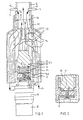
- FIG. 1 A sectional view through the hot air curling iron device 1 according to the invention is shown in FIG. 1.
- the motor-driven curling body 2 is only partially shown.
- the tine retraction mechanism is also omitted, since such a mechanism is already known from DE-29 44 050 A1 and can be used according to the invention.
- the curling body 2 has at its free end an actuating element, not shown here, for the insertion of the tines 3.
- the curling body 2 is axially detachably connected to the device 1 by means of a coupling 4, whereby the curling body 2 can be set in rotation.
- a clutch 4 either a snap-in clutch or a permanent magnet clutch 5 can be provided.
- the magnetic coupling 5 consists on the side of the curling winding body of a shaft journal with an embedded permanent magnet 6 and a magnetizable clutch drive disk 7, which is slightly hollow-bell-shaped due to a centering function.
- the clutch 5 is driven by a motor 8 and a gear 9.
- a hot air device not shown here, generates hot air 10 when the device is in operation, as shown by the arrows 11 and 12.
- the cold air blown in by the arrows 11, 12 is heated by the electric heating coil 13 and flows through openings 14 and 18 into a hollow shaft 15 which has longitudinal holes 18 arranged in a radially uniform distribution between the two bearings 16, 17, whereby the hot air can reach the inside of the hollow curling body 2 and can emerge through openings 19, both in the free openings 19 and in the openings 19 covered with a prong 3.
- the cylindrical part of the curling body 2 is also heated (and with him the strand of hair wound on it).
- the first bearing 16 has a larger diameter X than the second bearing 17 with a diameter Y.
- the clutch 4, 5 is provided with a radial play compensation device 20, as a result of which greater structural tolerances between the axes of the transmission 9 and clutch drive disk 7 can be compensated.
- the clutch drive disk 7 is provided transversely to a drive shaft 25 with a fixed drive pin 26 which runs with a little play across a bore 27 of the drive shaft 75. To remove the curling body 2 for cleaning or replacement, it can be easily separated from the coupling 4, 5 by a slight axial force and removed from the device.
- the curling body 2 has an actuating element 22 which interacts with a tine retraction mechanism (not shown here) such that the tines 3 can be retracted by preferably axially displacing the actuating element 22.
- the curling body 2 'according to FIG. 4 differs from the curling body 2 according to FIG. 3 in that it has a larger bobbin diameter and that the actuating element 22' is additionally provided with a compartment tip. In this function is suitable the compartment tip 23 especially for axial actuation for retracting the tines 3.
Landscapes
- Hair Curling (AREA)
- Manufacture Of Iron (AREA)
- Heat Treatment Of Strip Materials And Filament Materials (AREA)
- Drying Of Solid Materials (AREA)
- Apparatus For Disinfection Or Sterilisation (AREA)
Abstract
Description
- Die Erfindung betrifft ein Heißluftlockenstabgerät mit einem mit radial angeordneten Zinken versehenen motorangetriebenen Lockenwickelkörper.
- Ein derartiges Gerät ist aus der DE-35 29 267 A1 bekannt und dient zum Formen von Haarlocken, wobei jeweils eine Haarsträhne motorisch auf den Lockenwickelkörper gewickelt wird. Nach einer kurzen Behandlungsdauer der Locke mit aus dem Wickelkörper strömender Warmluft wird der Lockenwickelkörper axial entriegelt und unter Ausübung von Zugkraft der Locke aus dem eingewickelten Haar ausgerollt. Durch diesen Vorgang verliert die gelegte Locke einen Teil ihrer Spannkraft, insbesondere wenn die Locke vor dem Ausrollen des Wickelkörpers noch nicht mit dem Raumklima konditioniert ist.
- Es ist daher Aufgabe der Erfindung, ein Gerät nach dem Oberbegriff des Anspruchs 1 zu schaffen, das den oben genannten Nachteil nicht aufweist, weiterhin vielseitige Anwendungsmöglichkeiten eröffnet und eine einfache Handhabung bei größter mechanischer Stabilität aufweist.
- Gelöst wird diese Aufgabe gemäß dem kennzeichnenden Teil des Anspruchs 1. Weitere vorteilhafte Ausgestaltungen der Erfindung gehen aus den Unteransprüchen hervor.
- Dadurch, daß der Lockenwickelkörper mit einziehbaren Zinken versehen ist, kann der Lockenwickelkörper axial von der Haarlocke gezogen werden, wodurch diese in ihrer ursprünglichen Form mit dem Raumklima konditionieren kann. Dadurch wird eine optimale Spannkraft der Locke erzielt.
- Ein besonders einfacher konstruktiver Aufbau eines Zinkeneinzugsmechanismus ist dadurch gegeben, daß der Locken wickelkörper an seinem freien Ende ein Betätigungselement für den Zinkeneinzug aufweist. Je nach Zinkeneinzugsmechanismus kann das Betätigungselement wahlweise axial oder radial betätigbar ausgebildet sein.
- Eine vorteilhafte Zusatzfunktion ist dadurch gegeben, daß das Betätigungselement als Abteilspitze ausgestaltet ist. Dadurch kann mit dem Gerät mittels der Abteilspitze eine Strähne abgeteilt werden. Wahlweise kann die Abteilspitze zum Betätigen des Zinkeneinzugsmechanismus axial oder radial betätigbar ausgebildet sein.
- Vielseitige Anwendungsmöglichkeiten und eine einfache Handhabung des Heißluftlockenstabgeräts sind dadurch gegeben, daß der Lockenwickelkörper mit dem Gerät axial lösbar mit einer Kupplung verbunden ist, wodurch schnell und einfach der Lockenwickelkörper ausgewechselt werden kann, z. B. um einen Lockenwickelkörper mit einem größeren Wickeldurchmesser verwenden zu können.
- Eine besonders einfache Handhabung zum Auswechseln der Lockenwickelkörper ist dadurch gegeben, daß die Kupplung als Rastkupplung oder Permanentmagnetkupplung vorgesehen ist, wodurch gleichzeitig eine Rutschkupplung realisierbar ist, die eine zu hohe Drehmomentübertragung verhindert.
- Zum Ausgleich radialer Toleranzen zwischen dem Wellenzapfen und der Antriebskupplungsscheibe ist diese mit einer Ausgleichseinrichtung versehen.
- Für eine sehr große axiale Stabilität zwischen dem Lockenwickelkörper und dem Heißluftlockenstabgerät ist vorgesehen, daß der Lockenwickelkörper einseitig axial mit einer Welle verbunden ist und in Nähe des Lockenwickelkörpers mit einem ersten Lager und am Wellenzapfen mit einem zweiten Lager des Heißluftlockenstabgeräts korrespon diert. Dadurch werden die quer zur Längsachse des Lockenwickelkörpers angreifenden Kräfte auf die beiden Lager verteilt.
- Den Zapfen mit einem Permanentmagneten zu versehen hat den Vorteil, daß im anderen Fall, die Antriebskupplungsscheibe innerhalb des Heißluftlockenstabgeräts mit einem Permanentmagneten zu versehen den Nachteil hätte, daß versehentlich in das Gerät hineinfallende magnetisierbare Teile nur noch sehr schwer aus dem Gerät entnehmbar wären und damit die Funktionssicherheit des Geräts beeinträchtigen würde.
- Zur Versorgung des Wickelkörpers mit Heißluft ist der Lockenwickelkörper und die Welle bis zwischen den beiden Lagern hohl ausgebildet und weist zwischen den Lagern radial gleichmäßig verteilte angeordnete Längslöcher auf, durch die die Heißluft entlang der Hohlwelle bis zum Lockenwickelkörper geführt wird und da von innen her nach außen treten kann. Um beim Herausnehmen bzw. beim Auswechseln der Lockenwickelkörper bei laufendem Gerät nicht einen Heißluftstau innerhalb des Geräts zu verursachen, ist das erste Lager mit einem größeren Durchmesser versehen als das zweite Lager. Dadurch kann beim Ein- oder Ausführen der Welle gestaute Heißluft zwischen dem Wellenzapfen und dem ersten Lager ungehindert durchströmen.
- Die Auswechselmöglichkeit des Lockenwickelkörpers hat zudem auch den Vorteil, daß dieser separat durch leichte Handhabung gereinigt, desinfiziert oder auch gegen einen defekten ausgetauscht werden kann.
- Die Erfindung wird anhand von 3 Figuren näher beschrieben.
- Es zeigt:
- Fig. 1 einen teilweisen Schnitt durch ein Heißluftlocken stabgerät mit einer Magnetkupplung;
- Fig. 2 in einem Ausschnitt eine Rastkupplung;
- Fig. 3 in einer Draufsicht ein Lockenwickelkörper;
- Fig. 4 einen Lockenwickelkörper gemäß der Fig. 3 jedoch mit einem größeren Wickelkörperdurchmesser und einer Abteilspitze.
- Eine Schnittdarstellung durch das erfindungsgemäße Heißluftlockenstabgerät 1 ist in der Fig. 1 dargestellt. Der motorangetriebene Lockenwickelkörper 2 ist nur teilweise dargestellt. Ebenso ist der Zinkeneinzugsmechanismus fortgelassen, da ein solcher bereits in der DE-29 44 050 A1 bekannt ist und erfindungsgemäß verwendet werden kann. Der Lockenwickelkörper 2 weist an seinem freien Ende ein hier nicht dargestelltes Betätigungselement für den Einzug der Zinken 3 auf. Der Lockenwickelkörper 2 ist mit dem Gerät 1 axial lösbar mittels einer Kupplung 4 verbunden, wodurch der Lockenwickelkörper 2 in Rotationen versetzt werden kann. Als Kupplung 4 kann wahlweise eine Rastkupplung oder auch eine Permanentmagnetkupplung 5 vorgesehen werden. Die Magnetkupplung 5 besteht lockenwickelkörperseitig aus einem Wellenzapfen mit einem eingelassenen Permanentmagneten 6 und einer magnetisierbaren Kupplungsantriebsscheibe 7, die wegen einer Zentrierfunktion leicht hohlglockenförmig ausgebildet ist. Die Kupplung 5 wird mittels eines Motors 8 und eines Getriebes 9 angetrieben. Eine hier nicht dargestellte Heißlufteinrichtung erzeugt bei Betrieb des Geräts Heißluft 10, wie durch die Pfeile 11 und 12 dargestellt. Die bei den Pfeilen 11, 12 eingeblasene Kaltluft wird durch die elektrische Heizwendel 13 erhitzt und strömt durch Öffnungen 14 und 18 in eine Hohlwelle 15, die zwischen den beiden Lagern 16, 17 radial gleichmäßig verteilt angeordnete Längslöcher 18 aufweist, wodurch die Heißluft das Innere des hohlen Lockenwickelkörpers 2 erreichen kann und durch Öffnungen 19 heraustreten kann, sowohl bei den freien Öffnungen 19 wie auch bei den mit einem Zinken 3 belegten Öffnungen 19. Bei diesem Vorgang wird auch der zylindrische Teil des Lockenwickelkörpers 2 erwärmt (und mit ihm die darauf aufgewickelte Haarsträhne).
- Das erste Lager 16 weist einen größeren Durchmesser X auf als das zweite Lager 17 mit einem Durchmesser Y.
- Die Kupplung 4, 5 ist mit einer Radialspielausgleichseinrichtung 20 versehen, wodurch größere Bautoleranzen zwischen den Achsen des Getriebes 9 und Kupplungsantriebsscheibe 7 ausgeglichen werden können. Hierzu ist die Kupplungsantriebsscheibe 7 quer zu einer Antriebswelle 25 mit einem festen Mitnahmestift 26 versehen, der mit etwas Spiel quer durch eine Bohrung 27 der Antriebswelle 75 verläuft. Zum Herausnehmen des Lockenwickelkörpers 2 zwecks Reinigung oder Auswechselns kann dieser leicht durch eine leichte Axialkraft von der Kupplung 4, 5 getrennt und aus dem Gerät herausgenommen werden.
- In der Fig. 2 ist in einem Ausschnitt eine entsprechende Rastkupplung 5′ dargestellt.
- In der Fig. 3 ist in einer Seitenansicht der vollständige Lockenwickelkörper 2 mit der Welle 24 dargestellt. Zum manuellen Einziehen der Zinken 3 weist der Lockenwickelkörper 2 ein Betätigungselement 22 auf, das mit einem hier nicht dargestellten Zinkeneinzugsmechanismus derart zusammenwirkt, daß durch vorzugsweise axiales Verschieben des Betätigungselements 22 die Zinken 3 eingezogen werden können.
- Der Lockenwickelkörper 2′ gemäß der Fig. 4 unterscheidet sich vom Lockenwickelkörper 2 nach der Fig. 3 dadurch, daß dieser einen größeren Wickelkörperdurchmesser aufweist und daß das Betätigungselement 22′ zusätzlich mit einer Abteilspitze versehen ist. In dieser Funktion eignet sich die Abteilspitze 23 besonders für eine axiale Betätigung zum Einziehen der Zinken 3.
-
- 1 Heißluftlockenstabgerät
- 2 Lockenwickelkörper
- 3 Zinken
- 4 Kupplung
- 5 Magnetkupplung
- 5′ Rastkupplung
- 6 Permanentmagnet
- 7 Kupplungsantriebsscheibe
- 8 Motor
- 9 Getriebe
- 10 Heißluft
- 11 Pfeil
- 12 Pfeil
- 13 Heizwendel
- 14 Heizwendel
- 15 Hohlwelle
- 16 erstes Lager
- 17 zweites Lager
- 18 Längsloch
- 19 Öffnungen
- 20 Axialspielausgleichseinrichtung
- 21 Wellenzapfen
- 22, 22′ Betätigungselement
- 23 Abteilspitze
- 24 Welle
- 25 Antriebswelle
- 26 Mitnahmestift
- 27 Bohrung
Claims (13)
Applications Claiming Priority (2)
| Application Number | Priority Date | Filing Date | Title |
|---|---|---|---|
| DE3837297A DE3837297A1 (de) | 1988-11-03 | 1988-11-03 | Heissluftlockenstabgeraet |
| DE3837297 | 1988-11-03 |
Publications (2)
| Publication Number | Publication Date |
|---|---|
| EP0367254A1 true EP0367254A1 (de) | 1990-05-09 |
| EP0367254B1 EP0367254B1 (de) | 1995-06-21 |
Family
ID=6366384
Family Applications (1)
| Application Number | Title | Priority Date | Filing Date |
|---|---|---|---|
| EP89120253A Expired - Lifetime EP0367254B1 (de) | 1988-11-03 | 1989-11-02 | Heissluftlockenstabgerät |
Country Status (7)
| Country | Link |
|---|---|
| US (1) | US5133372A (de) |
| EP (1) | EP0367254B1 (de) |
| JP (1) | JPH03502065A (de) |
| AT (1) | ATE123929T1 (de) |
| DE (2) | DE3837297A1 (de) |
| ES (1) | ES2076189T3 (de) |
| WO (1) | WO1990004937A1 (de) |
Families Citing this family (16)
| Publication number | Priority date | Publication date | Assignee | Title |
|---|---|---|---|---|
| US5348030A (en) * | 1992-10-14 | 1994-09-20 | Hirzel Suzy C | Retractable brush with upwardly angled teeth |
| US5887600A (en) * | 1997-12-23 | 1999-03-30 | Wilk; Sue | Hair curling brush and method of using same |
| DE29915051U1 (de) * | 1999-08-27 | 1999-12-09 | WIK Elektro-Hausgeräte-Vertriebsgesellschaft mbH & Co Produktionskommanditgesellschaft, 45355 Essen | Bürstenaufsatz für ein Warmlufthandgerät |
| US7015420B2 (en) * | 2003-12-08 | 2006-03-21 | Kenford Industrial Company Ltd. | Hair brushing appliance |
| US20090205672A1 (en) * | 2008-02-19 | 2009-08-20 | Mcdonald Val | Apparatus for separating hair |
| EP2524618A1 (de) * | 2011-05-19 | 2012-11-21 | Babyliss Faco S.A. | Aufrollvorrichtung für Lockenwickler |
| EP3091869A1 (de) * | 2013-10-28 | 2016-11-16 | TF3 Limited | Haarstylingvorrichtung |
| CN105873466B (zh) * | 2014-01-27 | 2019-01-29 | 有机美学有限公司 | 扭力可调整的卷发工具 |
| TW201922138A (zh) | 2017-10-17 | 2019-06-16 | 英商Hd3有限公司 | 頭髮造型裝置、頭髮造型方法及驅動系統 |
| GB2614463B (en) | 2018-06-15 | 2024-04-10 | Japham Group Ltd | Hair styling device |
| GB201902443D0 (en) | 2019-02-22 | 2019-04-10 | Hd3 Ltd | Hair styling device |
| USD973364S1 (en) | 2020-12-31 | 2022-12-27 | Conair Llc | Heated air styling brush |
| USD973363S1 (en) | 2020-12-31 | 2022-12-27 | Conair Llc | Heated air hair brush |
| USD974042S1 (en) | 2020-12-31 | 2023-01-03 | Conair Llc | Heated air hair brush |
| CN214854933U (zh) * | 2021-07-16 | 2021-11-26 | 广东鸿源电器科技有限公司 | 一种自动卷发棒 |
| CN117084492A (zh) * | 2023-08-22 | 2023-11-21 | 美平电器制品(深圳)有限公司 | 可更换接头的自动卷发器 |
Citations (9)
| Publication number | Priority date | Publication date | Assignee | Title |
|---|---|---|---|---|
| US3890984A (en) * | 1974-01-23 | 1975-06-24 | Alexander C Lesetar | Hair dryer with rotary brush |
| DE2502821A1 (de) * | 1975-01-24 | 1976-07-29 | Dieter W Liedtke | Haarpflege- und frisiergeraet |
| FR2419044A1 (fr) * | 1978-03-09 | 1979-10-05 | Dentsply Int Inc | Peigne tubulaire pour cheveux, a dents retractables |
| DE2825099A1 (de) * | 1978-06-08 | 1979-12-13 | Braun Ag | Vorrichtung zur haarbehandlung |
| DE3119085A1 (de) * | 1981-05-14 | 1982-12-02 | Erwin 7967 Bad Waldsee Hymer | Foenbuerste |
| DE3121848A1 (de) * | 1981-06-02 | 1982-12-23 | geb. Ehrmuth Heide 8100 Garmisch-Partenkirchen Brehm | Haarpflegestab |
| DE3215232A1 (de) * | 1982-04-23 | 1983-10-27 | Wella Ag, 6100 Darmstadt | Verfahren zur umformung einer haarstraehne durch erwaermung und haarumformgeraet hierfuer |
| EP0168099A2 (de) * | 1984-07-06 | 1986-01-15 | F A C O Société Anonyme: | Blasende Bürste zum Wellen der Haare |
| DE3529267A1 (de) * | 1985-08-16 | 1987-02-26 | Schuermann Hans Peter | Foen-frisierstab mit drehbarer rundbuerste |
Family Cites Families (10)
| Publication number | Priority date | Publication date | Assignee | Title |
|---|---|---|---|---|
| BE632129A (de) * | 1962-05-09 | |||
| US3265075A (en) * | 1963-09-19 | 1966-08-09 | Gen Electric | Hair curling and drying apparatus with magnetic coupling |
| US3750680A (en) * | 1972-06-12 | 1973-08-07 | B Miller | Teasing comb |
| US3863652A (en) * | 1973-08-31 | 1975-02-04 | Malibu Personal Beauty Product | Electrically driven heated hair curling or setting device |
| US3894547A (en) * | 1974-02-01 | 1975-07-15 | Malibu Personal Beauty Product | Hair styling apparatus |
| US4023578A (en) * | 1974-11-08 | 1977-05-17 | Etablissements Lardenois | Blow-wave brush |
| DE2944050C2 (de) * | 1979-10-31 | 1987-04-16 | Icomag Trust Reg., Vaduz | Lockenwickler |
| US4492241A (en) * | 1982-02-19 | 1985-01-08 | Windmere Corporation | Retractable curling brush |
| US4467821A (en) * | 1983-07-07 | 1984-08-28 | Conair Corporation | Actuator control for retractable bristle brushes |
| US4664132A (en) * | 1984-06-20 | 1987-05-12 | Kim Schillig | Motorized hair styling brush with removable dryer |
-
1988
- 1988-11-03 DE DE3837297A patent/DE3837297A1/de not_active Withdrawn
-
1989
- 1989-11-02 US US07/499,541 patent/US5133372A/en not_active Expired - Lifetime
- 1989-11-02 EP EP89120253A patent/EP0367254B1/de not_active Expired - Lifetime
- 1989-11-02 JP JP2500035A patent/JPH03502065A/ja active Pending
- 1989-11-02 ES ES89120253T patent/ES2076189T3/es not_active Expired - Lifetime
- 1989-11-02 WO PCT/EP1989/001309 patent/WO1990004937A1/de not_active Ceased
- 1989-11-02 DE DE58909306T patent/DE58909306D1/de not_active Expired - Fee Related
- 1989-11-02 AT AT89120253T patent/ATE123929T1/de not_active IP Right Cessation
Patent Citations (9)
| Publication number | Priority date | Publication date | Assignee | Title |
|---|---|---|---|---|
| US3890984A (en) * | 1974-01-23 | 1975-06-24 | Alexander C Lesetar | Hair dryer with rotary brush |
| DE2502821A1 (de) * | 1975-01-24 | 1976-07-29 | Dieter W Liedtke | Haarpflege- und frisiergeraet |
| FR2419044A1 (fr) * | 1978-03-09 | 1979-10-05 | Dentsply Int Inc | Peigne tubulaire pour cheveux, a dents retractables |
| DE2825099A1 (de) * | 1978-06-08 | 1979-12-13 | Braun Ag | Vorrichtung zur haarbehandlung |
| DE3119085A1 (de) * | 1981-05-14 | 1982-12-02 | Erwin 7967 Bad Waldsee Hymer | Foenbuerste |
| DE3121848A1 (de) * | 1981-06-02 | 1982-12-23 | geb. Ehrmuth Heide 8100 Garmisch-Partenkirchen Brehm | Haarpflegestab |
| DE3215232A1 (de) * | 1982-04-23 | 1983-10-27 | Wella Ag, 6100 Darmstadt | Verfahren zur umformung einer haarstraehne durch erwaermung und haarumformgeraet hierfuer |
| EP0168099A2 (de) * | 1984-07-06 | 1986-01-15 | F A C O Société Anonyme: | Blasende Bürste zum Wellen der Haare |
| DE3529267A1 (de) * | 1985-08-16 | 1987-02-26 | Schuermann Hans Peter | Foen-frisierstab mit drehbarer rundbuerste |
Also Published As
| Publication number | Publication date |
|---|---|
| EP0367254B1 (de) | 1995-06-21 |
| WO1990004937A1 (de) | 1990-05-17 |
| DE58909306D1 (de) | 1995-07-27 |
| DE3837297A1 (de) | 1990-05-10 |
| JPH03502065A (ja) | 1991-05-16 |
| ATE123929T1 (de) | 1995-07-15 |
| US5133372A (en) | 1992-07-28 |
| ES2076189T3 (es) | 1995-11-01 |
Similar Documents
| Publication | Publication Date | Title |
|---|---|---|
| EP0367254B1 (de) | Heissluftlockenstabgerät | |
| DE19721064A1 (de) | Ablöseverhinderungsmechanismus und Strauchschneider, welcher mit einem Ablöseverhinderungsmechanismus ausgestattet ist | |
| DE2502821C3 (de) | Hand-Haarpflegegerät | |
| DE3544439A1 (de) | Verfahren und vorrichtung zum herstellen von einzelkabeln mit optischen fasern oder komponenten von optischen faserkabeln fuer nachrichtenuebertragung | |
| DE69001186T2 (de) | Vorrichtung mit auf- und abwickler zur vermeidung der torsion in dem verbindingskabel der rotierenden kupplung. | |
| DE4424479A1 (de) | Reibungskupplung mit einem Schwungrad | |
| WO2014063782A1 (de) | Aktuator für ein chirurgisches instrument | |
| DE8813717U1 (de) | Heißluftlockenstabgerät | |
| DE2238485A1 (de) | Verfahren und vorrichtung zum kontinuierlichen herstellen von drahtseil | |
| DE3116866A1 (de) | "kupplungsgehaeuse fuer kupplungen" | |
| LU101351B1 (de) | Rohrmotorset | |
| DE2342679A1 (de) | Spannhuelsenanordnung fuer zahnaerztliche handstuecke | |
| EP0000729A1 (de) | Wickelwelle zum Aufwickeln mehrerer Bänder gleichzeitig | |
| DE4233638A1 (de) | Vorrichtung zum Aufspulen mindestens eines synthetischen Fadens | |
| EP1294079A2 (de) | Elektromotor mit einem Aufnahmeraum für einen Temperaturfühler | |
| DE2501935C2 (de) | Dauer- oder wasserwellwickel | |
| DE4041693C2 (de) | ||
| DE2636868A1 (de) | Spule fuer einen gekruemmten stabbreithalter, sowie damit ausgestatteter breithalter | |
| DE69720268T2 (de) | In einem verfahren zur behandlung von fasern brauchbare anordnung | |
| DE102021119563A1 (de) | Medizinisches Instrument | |
| DE343097C (de) | Elastische Kupplung | |
| DE3418973A1 (de) | Folienlager und ein verfahren zu seiner herstellung | |
| DE1471912C (de) | Vorrichtung zur Herstellung eines Faserbündels zur optischen Bildübertragung | |
| AT83207B (de) | Aufwickelvorrichtung für starke Papier- oder ähnliche Lagen auf im Verhältnis zu ihrer Länge schwache Wickelstäbe. | |
| DE7634658U1 (de) | Dynamo fuer tachometrische zwecke |
Legal Events
| Date | Code | Title | Description |
|---|---|---|---|
| PUAI | Public reference made under article 153(3) epc to a published international application that has entered the european phase |
Free format text: ORIGINAL CODE: 0009012 |
|
| 17P | Request for examination filed |
Effective date: 19891102 |
|
| AK | Designated contracting states |
Kind code of ref document: A1 Designated state(s): AT BE CH DE ES FR GB GR IT LI LU NL SE |
|
| 17Q | First examination report despatched |
Effective date: 19920205 |
|
| GRAA | (expected) grant |
Free format text: ORIGINAL CODE: 0009210 |
|
| AK | Designated contracting states |
Kind code of ref document: B1 Designated state(s): AT BE CH DE ES FR GB GR IT LI LU NL SE |
|
| PG25 | Lapsed in a contracting state [announced via postgrant information from national office to epo] |
Ref country code: NL Free format text: LAPSE BECAUSE OF NON-PAYMENT OF DUE FEES Effective date: 19950621 Ref country code: GR Free format text: LAPSE BECAUSE OF FAILURE TO SUBMIT A TRANSLATION OF THE DESCRIPTION OR TO PAY THE FEE WITHIN THE PRESCRIBED TIME-LIMIT Effective date: 19950621 Ref country code: BE Effective date: 19950621 |
|
| REF | Corresponds to: |
Ref document number: 123929 Country of ref document: AT Date of ref document: 19950715 Kind code of ref document: T |
|
| REF | Corresponds to: |
Ref document number: 58909306 Country of ref document: DE Date of ref document: 19950727 |
|
| ITF | It: translation for a ep patent filed | ||
| ET | Fr: translation filed | ||
| GBT | Gb: translation of ep patent filed (gb section 77(6)(a)/1977) |
Effective date: 19950814 |
|
| PG25 | Lapsed in a contracting state [announced via postgrant information from national office to epo] |
Ref country code: SE Effective date: 19950921 |
|
| PGFP | Annual fee paid to national office [announced via postgrant information from national office to epo] |
Ref country code: GB Payment date: 19951016 Year of fee payment: 7 |
|
| PGFP | Annual fee paid to national office [announced via postgrant information from national office to epo] |
Ref country code: FR Payment date: 19951019 Year of fee payment: 7 |
|
| REG | Reference to a national code |
Ref country code: ES Ref legal event code: FG2A Ref document number: 2076189 Country of ref document: ES Kind code of ref document: T3 |
|
| PG25 | Lapsed in a contracting state [announced via postgrant information from national office to epo] |
Ref country code: AT Effective date: 19951102 |
|
| PGFP | Annual fee paid to national office [announced via postgrant information from national office to epo] |
Ref country code: ES Payment date: 19951120 Year of fee payment: 7 |
|
| PG25 | Lapsed in a contracting state [announced via postgrant information from national office to epo] |
Ref country code: LU Free format text: LAPSE BECAUSE OF NON-PAYMENT OF DUE FEES Effective date: 19951130 Ref country code: LI Effective date: 19951130 Ref country code: CH Effective date: 19951130 |
|
| NLV1 | Nl: lapsed or annulled due to failure to fulfill the requirements of art. 29p and 29m of the patents act | ||
| PLBE | No opposition filed within time limit |
Free format text: ORIGINAL CODE: 0009261 |
|
| STAA | Information on the status of an ep patent application or granted ep patent |
Free format text: STATUS: NO OPPOSITION FILED WITHIN TIME LIMIT |
|
| 26N | No opposition filed | ||
| REG | Reference to a national code |
Ref country code: CH Ref legal event code: PL |
|
| PG25 | Lapsed in a contracting state [announced via postgrant information from national office to epo] |
Ref country code: GB Effective date: 19961102 |
|
| PG25 | Lapsed in a contracting state [announced via postgrant information from national office to epo] |
Ref country code: ES Free format text: LAPSE BECAUSE OF THE APPLICANT RENOUNCES Effective date: 19961104 |
|
| GBPC | Gb: european patent ceased through non-payment of renewal fee |
Effective date: 19961102 |
|
| PG25 | Lapsed in a contracting state [announced via postgrant information from national office to epo] |
Ref country code: FR Effective date: 19970731 |
|
| REG | Reference to a national code |
Ref country code: FR Ref legal event code: ST |
|
| REG | Reference to a national code |
Ref country code: ES Ref legal event code: FD2A Effective date: 20010402 |
|
| PGFP | Annual fee paid to national office [announced via postgrant information from national office to epo] |
Ref country code: DE Payment date: 20011031 Year of fee payment: 13 |
|
| PG25 | Lapsed in a contracting state [announced via postgrant information from national office to epo] |
Ref country code: DE Free format text: LAPSE BECAUSE OF NON-PAYMENT OF DUE FEES Effective date: 20030603 |
|
| PG25 | Lapsed in a contracting state [announced via postgrant information from national office to epo] |
Ref country code: IT Free format text: LAPSE BECAUSE OF NON-PAYMENT OF DUE FEES;WARNING: LAPSES OF ITALIAN PATENTS WITH EFFECTIVE DATE BEFORE 2007 MAY HAVE OCCURRED AT ANY TIME BEFORE 2007. THE CORRECT EFFECTIVE DATE MAY BE DIFFERENT FROM THE ONE RECORDED. Effective date: 20051102 |