EP0367295A2 - A method of detecting the position of an object pattern in an image - Google Patents
A method of detecting the position of an object pattern in an image Download PDFInfo
- Publication number
- EP0367295A2 EP0367295A2 EP89120503A EP89120503A EP0367295A2 EP 0367295 A2 EP0367295 A2 EP 0367295A2 EP 89120503 A EP89120503 A EP 89120503A EP 89120503 A EP89120503 A EP 89120503A EP 0367295 A2 EP0367295 A2 EP 0367295A2
- Authority
- EP
- European Patent Office
- Prior art keywords
- pattern
- value
- image
- area
- pixel
- Prior art date
- Legal status (The legal status is an assumption and is not a legal conclusion. Google has not performed a legal analysis and makes no representation as to the accuracy of the status listed.)
- Granted
Links
Images



Classifications
-
- G—PHYSICS
- G06—COMPUTING OR CALCULATING; COUNTING
- G06T—IMAGE DATA PROCESSING OR GENERATION, IN GENERAL
- G06T1/00—General purpose image data processing
-
- G—PHYSICS
- G06—COMPUTING OR CALCULATING; COUNTING
- G06T—IMAGE DATA PROCESSING OR GENERATION, IN GENERAL
- G06T7/00—Image analysis
- G06T7/70—Determining position or orientation of objects or cameras
- G06T7/73—Determining position or orientation of objects or cameras using feature-based methods
- G06T7/74—Determining position or orientation of objects or cameras using feature-based methods involving reference images or patches
-
- G—PHYSICS
- G06—COMPUTING OR CALCULATING; COUNTING
- G06T—IMAGE DATA PROCESSING OR GENERATION, IN GENERAL
- G06T2207/00—Indexing scheme for image analysis or image enhancement
- G06T2207/30—Subject of image; Context of image processing
- G06T2207/30108—Industrial image inspection
- G06T2207/30148—Semiconductor; IC; Wafer
Definitions
- the present invention relates to a method of detecting the position of an object pattern in an image, and more particularly, to a method of position recognition which may be suitably applied for recognizing an object pattern having good shape reproducibility such as a pattern on the surface of an integrated circuit.
- a position of a surface pattern of an integrated circuit is detected by a so-called template matching method in which a reference pattern having the shape to be detected has been previously registered as a template, an image is picked up by a television camera, the pattern of each section of the picked-up image is binary-coded, and then the binary-coded data of the pattern are sequentially compared with the template for detecting the position where the best matching between the two is obtained.
- Figure 5A shows a binary-coded template 51 in which the pattern to be detected is binary-coded by denoting a white pixel by the digit "1" and denoting a black pixel by the digit "0".
- a binary-coded image 52 to be inspected is shown in Fig. 5B.
- the template 51 is produced only in a computer, and not actually formed in a physical body as shown in Fig. 5A, and thus the processes described below are conducted in the computer.
- the template 51 is superimposed over an area in the top left-hand corner of the object image 52, and the matching status between the facing pixels is examined.
- the template 51 is moved by one pixel to the right for performing the examination in the same manner. Such examination is repeated until the template 51 is moved to the bottom right-hand corner of the image 52. Thereafter, the area having the highest matching rate is determined as the recognition point.
- the area indicated by C has the highest matching rate (i.e., 64), and, therefore, the area C is detected as the recognition point. In other words, the area C has the object pattern.
- the above method has a drawback in that, if the lightness of a body changes, the binary-coded image of the body also changes, leading to a recognition error or a total failure of recognition.
- the body from which the binary-coded image of Fig. 5B is obtained under a bright condition is processed under a dark condition to obtain a binary-coded image thereof, all pixels of the obtained binary-coded image turn into the state of "0", leaving no pixels in the state of "1". Therefore, the matching rate will become the same at any position, resulting in that the position of the object pattern cannot be determined.
- the above-mentioned drawback is caused also by changing the reflectivity of the body to be inspected or by changing the illuminance on the body.
- the method of detecting the position of an object pattern in an image of this invention comprises the steps of: (a) preparing a reference pattern which has a pattern and a background which are composed of one or more pixels each having a value regarding the brightness or gradation, the shape of said pattern corresponding to said object pattern, the value of each pixel of said pattern being different from that of each pixel of said background; (b) dividing said image into a plurality of sections; (c) selecting arbitrarily an area having two or more of said sections, the shape of said area corresponding to that of said reference pattern; (d) obtaining the brightness data from each of said sections; (e) obtaining a sum of products of the value of each pixel and the brightness data of each section corresponding to the pixel; (f) moving said area to another position in said image; (g) repeating steps (d) to (f); and (h) deciding that the area from which the sum having an extreme value is obtained is the one
- the extreme value is the largest value among said obtained sums.
- the extreme value is the smallest value among said obtained sums.
- the values of said pixels consist of 1, 0 and -1, and the total of said values is zero.
- the method of detecting the position of an object pattern in an image of this invention comprises the steps of: (a) preparing two or more reference patterns which have a pattern and a background, said pattern and background being composed of one or more pixels each having a value regarding the brightness or gradation, the shape obtained from said patterns when said reference patterns are arranged in a predetermined geometical or positional relationship corresponding to said object pattern, the value of each pixel of said pattern being different from that of each pixel of said background, a portion of each of said reference patterns being designated as a specific portion; (b) storing said positional relationship; (c) dividing said image into a plurality of sections; (d) selecting arbitrarily an area having two or more of said sections, the shape of said area corresponding to that of said reference pattern; (e) obtaining brightness data from each of said sections; (f) obtaining a sum of products of the value of each pixel of both said reference pattern and other reference patterns and the brightness data of each section corresponding to the pixel; (g) moving said area to another position
- the extreme value is the largest value among said obtained sums.
- the extreme value is the smallest value among said obtained sums.
- the values of said pixels consist of 1, 0 and -1, and the total of said values is zero.
- Figure 1 illustrates examples of a reference pattern useful in an embodiment of the invention.
- Fig. 1 show object patterns 1a, 1c and 1e, and (b), (d) and (f) reference patterns 1b, 1d and 1f which correspond to the object patterns 1a, 1c and 1e, respectively.
- the hatched portions indicate high-brightness and whitish areas.
- brightness factors are set so as to emphasize the contrast with the digit "1" designating a high-brightness portion and the digit "-1" a low-brightness portion. Pixels being at a position other than where the high-brightness portion border the low-brightness portion are allocated with the digit "0" so that the number of 1s equals the number of -1s as a result of normalization.
- FIG. 2B illustrates an image to be inspected in the embodiment of the invention.
- Each of the pixels is allocated with a brightness value or brightness data.
- the brightness data ranges from 21 to 51.
- a pixel having a higher brightness is allocated with a larger number, and a pixel having a lower brightness with a smaller number.
- the resulting image will become identical with the image 52 shown in Fig. 5B.
- the area is moved rightward by one pixel, and the calculations for obtaining the sum of products of the value of each pixel of the reference pattern 21 and the value of each section of the new area are performed in the same way as described above.
- the above procedure is repeated until the area comes to the bottom right-hand corner of the image, resulting in that the sum obtained from the area B shown in Fig. 2B is 1274 which is the greatest one.
- the area from which the greatest sum is obtained is the recognition point, i.e., the area has the object pattern. Therefore, it is recognized that the area B has the object pattern.
- the obtained sum is zero, facilitating the recognition of the object pattern. This is caused by the fact that, when normalized, the total of the values of pixels in the reference pattern 21 is zero.
- the invention may be performed using two or more reference patterns.
- the detection can be easily and reliably performed even when the image has similar patterns as shown in Fig. 4A.
- An example of the procedure of detecting an object pattern from the image 41 shown in Fig. 4A in which procedure two reference patterns are used will be described referring to Figs. 4A and 4B.
- Two reference patterns 42 and 43 are prepared, and their upper and left corners are designated as specific point a and b, respectively.
- a positional relationship ⁇ r between the specific points a and b is established so that, when the two reference patterns 42 and 43 are arranged in accordance with the positional relationship ⁇ r , the combination of the two reference patterns 42 and 43 corresponds to the object pattern.
- the determined positional relationship is stored in a memory of a computer. Then, the calculations for obtaining the sum of products are performed in the similar manner as described above, for the reference pattern 42. Selected are two areas from which the greatest two values are obtained, or from which the values greater than those of eight adjacent areas and being the greatest. The positions corresponding to the point a in the selected two areas are indicated by A1 and A2 in Fig. 4A. Then, the above is repeated for the reference pattern 43, and the positions corresponding to the point b in the selected two areas are indicated by B1 and B2 in Fig. 4A.
- the positional relationships ⁇ r1 to ⁇ r4 between the points A1, A2, B1 and B2 are obtained, and compared with the previously stored positional relationship ⁇ r , resulting in that the positional relationship ⁇ r3 is the one closest to the previously stored positional relationship ⁇ r .
- the areas corresponding to the points A2 and B1 having the positional relationship ⁇ r3 is recognized as the areas having the object pattern.
- the positional relationship ⁇ r may be designated by using either of an angle and a distance or by a combination of both.
- the brightness factor of each pixel of the reference pattern is set so that the greatest sum of products is obtained at the area having the object pattern.
- the brightness factor may be set so that the smallest sum of products is obtained at the area having the object pattern.
Landscapes
- Engineering & Computer Science (AREA)
- Physics & Mathematics (AREA)
- General Physics & Mathematics (AREA)
- Theoretical Computer Science (AREA)
- Computer Vision & Pattern Recognition (AREA)
- Image Analysis (AREA)
- Length Measuring Devices By Optical Means (AREA)
- Image Processing (AREA)
Abstract
Description
- The present invention relates to a method of detecting the position of an object pattern in an image, and more particularly, to a method of position recognition which may be suitably applied for recognizing an object pattern having good shape reproducibility such as a pattern on the surface of an integrated circuit.
- Conventionally, a position of a surface pattern of an integrated circuit is detected by a so-called template matching method in which a reference pattern having the shape to be detected has been previously registered as a template, an image is picked up by a television camera, the pattern of each section of the picked-up image is binary-coded, and then the binary-coded data of the pattern are sequentially compared with the template for detecting the position where the best matching between the two is obtained.
- This method will be described in more detail with reference to Figs. 5A and 5B. Figure 5A shows a binary-coded
template 51 in which the pattern to be detected is binary-coded by denoting a white pixel by the digit "1" and denoting a black pixel by the digit "0". A binary-codedimage 52 to be inspected is shown in Fig. 5B. In practice, thetemplate 51 is produced only in a computer, and not actually formed in a physical body as shown in Fig. 5A, and thus the processes described below are conducted in the computer. Thetemplate 51 is superimposed over an area in the top left-hand corner of theobject image 52, and the matching status between the facing pixels is examined. If "0" is superimposed on "0" or "1" on "1", it is determined that the pixels match each other. Next, thetemplate 51 is moved by one pixel to the right for performing the examination in the same manner. Such examination is repeated until thetemplate 51 is moved to the bottom right-hand corner of theimage 52. Thereafter, the area having the highest matching rate is determined as the recognition point. In the case of theimage 52, the area indicated by C has the highest matching rate (i.e., 64), and, therefore, the area C is detected as the recognition point. In other words, the area C has the object pattern. - However, the above method has a drawback in that, if the lightness of a body changes, the binary-coded image of the body also changes, leading to a recognition error or a total failure of recognition. For example, when the body from which the binary-coded image of Fig. 5B is obtained under a bright condition is processed under a dark condition to obtain a binary-coded image thereof, all pixels of the obtained binary-coded image turn into the state of "0", leaving no pixels in the state of "1". Therefore, the matching rate will become the same at any position, resulting in that the position of the object pattern cannot be determined. The above-mentioned drawback is caused also by changing the reflectivity of the body to be inspected or by changing the illuminance on the body.
- The method of detecting the position of an object pattern in an image of this invention, which overcomes the above-discussed and numerous other disadvantages and deficiencies of the prior art, comprises the steps of: (a) preparing a reference pattern which has a pattern and a background which are composed of one or more pixels each having a value regarding the brightness or gradation, the shape of said pattern corresponding to said object pattern, the value of each pixel of said pattern being different from that of each pixel of said background; (b) dividing said image into a plurality of sections; (c) selecting arbitrarily an area having two or more of said sections, the shape of said area corresponding to that of said reference pattern; (d) obtaining the brightness data from each of said sections; (e) obtaining a sum of products of the value of each pixel and the brightness data of each section corresponding to the pixel; (f) moving said area to another position in said image; (g) repeating steps (d) to (f); and (h) deciding that the area from which the sum having an extreme value is obtained is the one containing said object pattern.
- In a preferred embodiment, the extreme value is the largest value among said obtained sums.
- In a preferred embodiment, the extreme value is the smallest value among said obtained sums.
- In a preferred embodiment, the values of said pixels consist of 1, 0 and -1, and the total of said values is zero.
- The method of detecting the position of an object pattern in an image of this invention, comprises the steps of: (a) preparing two or more reference patterns which have a pattern and a background, said pattern and background being composed of one or more pixels each having a value regarding the brightness or gradation, the shape obtained from said patterns when said reference patterns are arranged in a predetermined geometical or positional relationship corresponding to said object pattern, the value of each pixel of said pattern being different from that of each pixel of said background, a portion of each of said reference patterns being designated as a specific portion; (b) storing said positional relationship; (c) dividing said image into a plurality of sections; (d) selecting arbitrarily an area having two or more of said sections, the shape of said area corresponding to that of said reference pattern; (e) obtaining brightness data from each of said sections; (f) obtaining a sum of products of the value of each pixel of both said reference pattern and other reference patterns and the brightness data of each section corresponding to the pixel; (g) moving said area to another position in said image; (h) repeating steps (e) to (g); (i) selecting two or more portions from which the sum having an extreme value or a value adjacent to said extreme value is obtained, for both said reference pattern and other reference patterns; (j) obtaining the position in each of said selected portions which corresponds to said specific part or said other specific part; (k) obtaining the positional relationships in each pair of said obtained positions; (l) obtaining the pair having the positional relationship which is closest to said stored positional relationship; and (m) deciding that the area which corresponds to said obtained pair is the one containing said object pattern.
- In a preferred embodiment, the extreme value is the largest value among said obtained sums.
- In a preferred embodiment, the extreme value is the smallest value among said obtained sums.
- In a preferred embodiment, the values of said pixels consist of 1, 0 and -1, and the total of said values is zero.
- Thus, the invention described herein makes possible the objectives of:
- (1) providing a method of detecting the position of an object pattern in an image in which the position can be accurately and stably detected even when the image has been obtained under a dark condition;
- (2) providing a method of detecting the position of an object pattern in an image in which the position can be accurately and stably detected even when the image has been obtained from a body the reflectivity of which changes; and
- (3) providing a method of detecting the position of an object pattern in an image in which the position can be accurately and stably detected even when the image has been obtained under a changing illumination.
- This invention may be better understood and its numerous objects and advantages will become apparent to those skilled in the art by reference to the accompanying drawings as follows:
- Figure 1 illustrates examples object patterns and reference patterns.
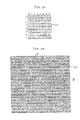
- Figure 2A illustrates a reference pattern used in an embodiment of the invention.
- Figure 2B illustrates an image coded by brightness data from which the position of the object pattern is detected using the reference pattern of Fig. 2A.
- Figure 3 illustrates an image which is obtained when the image of Fig. 2B darkens.
- Figure 4A is a diagram for illustrating another embodiment of the invention.
- Figure 4B is a diagram for illustrating the geometical or positional relationship of two reference patterns used in the other embodiment.
- Figure 5A illustrates a template used in a prior art method.
- Figure 5B illustrates a binary-coded image used in a prior art method.
- Figure 1 illustrates examples of a reference pattern useful in an embodiment of the invention. In Fig. 1, (a), (c) and (e) show object patterns 1a, 1c and 1e, and (b), (d) and (f) reference patterns 1b, 1d and 1f which correspond to the object patterns 1a, 1c and 1e, respectively. In the object patterns 1a, 1c and 1e, the hatched portions indicate high-brightness and whitish areas. The reference patterns 1b, 1d and 1f are divided into 64(=8x8) sections or pixels. Each pixel is allocated with a brightness factor (1, 0 or -1) so that the reference patterns 1b, 1d and 1f represent respectively the object patterns 1a, 1c and 1e. In the embodiment, brightness factors are set so as to emphasize the contrast with the digit "1" designating a high-brightness portion and the digit "-1" a low-brightness portion. Pixels being at a position other than where the high-brightness portion border the low-brightness portion are allocated with the digit "0" so that the number of 1s equals the number of -1s as a result of normalization.
- Figure 2B illustrates an image to be inspected in the embodiment of the invention. The
image 22 of Fig. 2B is divided into 380(=20x19) sections (hereinafter, referred to as "pixels"). Each of the pixels is allocated with a brightness value or brightness data. In theimage 22, the brightness data ranges from 21 to 51. A pixel having a higher brightness is allocated with a larger number, and a pixel having a lower brightness with a smaller number. If theimage 22 is reformed in a binary-coded image under the conditions that, for example, the value of 40 is set as the threshold, pixels having a value greater than 40 are designated by "1", and pixels having a value smaller than 40 are designated by "0", the resulting image will become identical with theimage 52 shown in Fig. 5B. - The procedures of detecting the position of the reference pattern shown in Fig. 2A (which is identical with the pattern 1b shown in (b) of Fig. 1) in the
image 22 of Fig. 2B will be described. First, thereference pattern 21 is superimposed over theimage 22 as shown by A in Fig. 2B. Then, the calculations for obtaining the sum of products of the value of each pixel of thereference pattern 21 and the value of each section of the area A are performed. That is, when the brightness factor of each pixel positioning at the ith row and jth column is denoted by Mij (both i and j ranging from 0 to 7) and the brightness data of each pixel positioning at the ith row and jth column in the area A denoted by Sij, the calculation of Σ(Mij·Sij) is performed. The calculation thus performed produces the result of -4. - Next, the area is moved rightward by one pixel, and the calculations for obtaining the sum of products of the value of each pixel of the
reference pattern 21 and the value of each section of the new area are performed in the same way as described above. The above procedure is repeated until the area comes to the bottom right-hand corner of the image, resulting in that the sum obtained from the area B shown in Fig. 2B is 1274 which is the greatest one. In the embodiment, the area from which the greatest sum is obtained is the recognition point, i.e., the area has the object pattern. Therefore, it is recognized that the area B has the object pattern. In an area where there is no variation in brightness, the obtained sum is zero, facilitating the recognition of the object pattern. This is caused by the fact that, when normalized, the total of the values of pixels in thereference pattern 21 is zero. - With reference to Fig. 3, the procedure in the case where the image to be inspected is dark will be described. In this case, the brightness data of each pixel of the
image 22 becomes small and varies in a small range, as shown in Fig. 3. The calculations for obtaining the sum of products are conducted for each area in the same manner as described above, resulting in that the sum obtained from the area A is -4 and that from the area B is 302. The latter is the greatest one among the sums obtained from theimage 22 shown in Fig. 3. In this way, even when the image is dark, it can be easily and reliably recognized that the area B has the object pattern. - When another pattern such as shown in (c) or (e) of Fig. 1 is to be detected, the procedure is conducted in the same manner as described above using another reference pattern such as shown in (b) or (d) of Fig. 1.
- Further, the invention may be performed using two or more reference patterns. In this case, the detection can be easily and reliably performed even when the image has similar patterns as shown in Fig. 4A. An example of the procedure of detecting an object pattern from the
image 41 shown in Fig. 4A in which procedure two reference patterns are used will be described referring to Figs. 4A and 4B. Tworeference patterns 
reference patterns 
reference patterns reference pattern 42. Selected are two areas from which the greatest two values are obtained, or from which the values greater than those of eight adjacent areas and being the greatest. The positions corresponding to the point a in the selected two areas are indicated by A1 and A2 in Fig. 4A. Then, the above is repeated for thereference pattern 43, and the positions corresponding to the point b in the selected two areas are indicated by B1 and B2 in Fig. 4A. The positional relationships


- In the above-described embodiments, the brightness factor of each pixel of the reference pattern is set so that the greatest sum of products is obtained at the area having the object pattern. Alternatively, the brightness factor may be set so that the smallest sum of products is obtained at the area having the object pattern.
- It is understood that various other modifications will be apparent to and can be readily made by those skilled in the art without departing from the scope and spirit of this invention. Accordingly, it is not intended that the scope of the claims appended hereto be limited to the description as set forth herein, but rather that the claims be construed as encompassing all the features of patentable novelty that reside in the present invention, including all features that would be treated as equivalents thereof by those skilled in the art to which this invention pertains.
Claims (8)
Applications Claiming Priority (2)
| Application Number | Priority Date | Filing Date | Title |
|---|---|---|---|
| JP63278691A JPH07117377B2 (en) | 1988-11-04 | 1988-11-04 | Position recognition method |
| JP278691/88 | 1988-11-04 |
Publications (3)
| Publication Number | Publication Date |
|---|---|
| EP0367295A2 true EP0367295A2 (en) | 1990-05-09 |
| EP0367295A3 EP0367295A3 (en) | 1992-08-12 |
| EP0367295B1 EP0367295B1 (en) | 1997-01-15 |
Family
ID=17600832
Family Applications (1)
| Application Number | Title | Priority Date | Filing Date |
|---|---|---|---|
| EP89120503A Expired - Lifetime EP0367295B1 (en) | 1988-11-04 | 1989-11-06 | A method of detecting the position of an object pattern in an image |
Country Status (4)
| Country | Link |
|---|---|
| EP (1) | EP0367295B1 (en) |
| JP (1) | JPH07117377B2 (en) |
| KR (1) | KR920005243B1 (en) |
| DE (1) | DE68927662T2 (en) |
Cited By (4)
| Publication number | Priority date | Publication date | Assignee | Title |
|---|---|---|---|---|
| EP0586708A4 (en) * | 1992-03-06 | 1994-07-27 | Omron Tateisi Electronics Co | Image processor, method therefor and apparatus using the image processor |
| FR2726078A1 (en) * | 1994-10-24 | 1996-04-26 | 3 14 Ingenierie | PROCEDURE FOR CHECKING THE RESPECTIVE LOCATION OF PATTERNS ON A TABLE OF MATERIAL |
| US20130223729A1 (en) * | 2012-02-28 | 2013-08-29 | Snell Limited | Identifying points of interest in an image |
| US20160055642A1 (en) * | 2012-02-28 | 2016-02-25 | Snell Limited | Identifying points of interest in an image |
Families Citing this family (1)
| Publication number | Priority date | Publication date | Assignee | Title |
|---|---|---|---|---|
| US7190809B2 (en) | 2002-06-28 | 2007-03-13 | Koninklijke Philips Electronics N.V. | Enhanced background model employing object classification for improved background-foreground segmentation |
Family Cites Families (2)
| Publication number | Priority date | Publication date | Assignee | Title |
|---|---|---|---|---|
| US4581762A (en) * | 1984-01-19 | 1986-04-08 | Itran Corporation | Vision inspection system |
| JPS61250504A (en) * | 1985-04-27 | 1986-11-07 | Omron Tateisi Electronics Co | Visual sensation sensor for confirming moving body |
-
1988
- 1988-11-04 JP JP63278691A patent/JPH07117377B2/en not_active Expired - Fee Related
-
1989
- 1989-11-04 KR KR1019890015989A patent/KR920005243B1/en not_active Expired
- 1989-11-06 EP EP89120503A patent/EP0367295B1/en not_active Expired - Lifetime
- 1989-11-06 DE DE68927662T patent/DE68927662T2/en not_active Expired - Fee Related
Cited By (7)
| Publication number | Priority date | Publication date | Assignee | Title |
|---|---|---|---|---|
| EP0586708A4 (en) * | 1992-03-06 | 1994-07-27 | Omron Tateisi Electronics Co | Image processor, method therefor and apparatus using the image processor |
| US5621825A (en) * | 1992-03-06 | 1997-04-15 | Omron Corporation | Image processor, image processing method and apparatus applying same |
| FR2726078A1 (en) * | 1994-10-24 | 1996-04-26 | 3 14 Ingenierie | PROCEDURE FOR CHECKING THE RESPECTIVE LOCATION OF PATTERNS ON A TABLE OF MATERIAL |
| EP0709651A1 (en) * | 1994-10-24 | 1996-05-01 | S.A.R.L.: 3,14 Ingenierie | Process for controlling the relative positioning of patterns on a sheet of material |
| US20130223729A1 (en) * | 2012-02-28 | 2013-08-29 | Snell Limited | Identifying points of interest in an image |
| US20160055642A1 (en) * | 2012-02-28 | 2016-02-25 | Snell Limited | Identifying points of interest in an image |
| US9977992B2 (en) | 2012-02-28 | 2018-05-22 | Snell Advanced Media Limited | Identifying points of interest in an image |
Also Published As
| Publication number | Publication date |
|---|---|
| DE68927662T2 (en) | 1997-05-28 |
| DE68927662D1 (en) | 1997-02-27 |
| JPH02126105A (en) | 1990-05-15 |
| EP0367295B1 (en) | 1997-01-15 |
| KR920005243B1 (en) | 1992-06-29 |
| EP0367295A3 (en) | 1992-08-12 |
| KR900008843A (en) | 1990-06-03 |
| JPH07117377B2 (en) | 1995-12-18 |
Similar Documents
| Publication | Publication Date | Title |
|---|---|---|
| US5226095A (en) | Method of detecting the position of an object pattern in an image | |
| EP0253397B1 (en) | Shape recognition method | |
| US5337369A (en) | Equipment for fingerprint pattern classification | |
| US5490225A (en) | Method and system for comparing two images by making an initial rough judgement | |
| US5703969A (en) | System and method for recognizing visual indicia | |
| US4581762A (en) | Vision inspection system | |
| KR100673423B1 (en) | Detection of defects by segmentation of images | |
| US8861845B2 (en) | Detecting and correcting redeye in an image | |
| US6289117B1 (en) | Analysis of an image of a pattern of discrete objects | |
| US5668898A (en) | Device for detecting the inclination of image | |
| US4962541A (en) | Pattern test apparatus | |
| EP0689152A2 (en) | Two dimensional management pattern | |
| US5638460A (en) | Method of evaluating object based upon image processing and inspection apparatus using said method | |
| Subasic et al. | Face image validation system | |
| EP0367295A2 (en) | A method of detecting the position of an object pattern in an image | |
| US5058177A (en) | Method for inspection of protruding features | |
| US5568564A (en) | Image processing apparatus and method for inspecting defects of enclosures of semiconductor devices | |
| US5392364A (en) | Object inspection method employing selection of discerning features using mahalanobis distances | |
| US5912985A (en) | Pattern detection method | |
| EP0651337A1 (en) | Object recognizing method, its apparatus, and image processing method and its apparatus | |
| JPH03204089A (en) | Image processing method | |
| US6985609B2 (en) | Method for identifying an object image | |
| US5655031A (en) | Method for determining attributes using neural network and fuzzy logic | |
| US7502524B2 (en) | Method and apparatus of processing a skin print image | |
| JPH04346011A (en) | Visual inspection apparatus for soldered state |
Legal Events
| Date | Code | Title | Description |
|---|---|---|---|
| PUAI | Public reference made under article 153(3) epc to a published international application that has entered the european phase |
Free format text: ORIGINAL CODE: 0009012 |
|
| 17P | Request for examination filed |
Effective date: 19891106 |
|
| AK | Designated contracting states |
Kind code of ref document: A2 Designated state(s): DE FR GB |
|
| PUAL | Search report despatched |
Free format text: ORIGINAL CODE: 0009013 |
|
| AK | Designated contracting states |
Kind code of ref document: A3 Designated state(s): DE FR GB |
|
| 17Q | First examination report despatched |
Effective date: 19940824 |
|
| GRAG | Despatch of communication of intention to grant |
Free format text: ORIGINAL CODE: EPIDOS AGRA |
|
| GRAH | Despatch of communication of intention to grant a patent |
Free format text: ORIGINAL CODE: EPIDOS IGRA |
|
| GRAH | Despatch of communication of intention to grant a patent |
Free format text: ORIGINAL CODE: EPIDOS IGRA |
|
| GRAA | (expected) grant |
Free format text: ORIGINAL CODE: 0009210 |
|
| AK | Designated contracting states |
Kind code of ref document: B1 Designated state(s): DE FR GB |
|
| REF | Corresponds to: |
Ref document number: 68927662 Country of ref document: DE Date of ref document: 19970227 |
|
| ET | Fr: translation filed | ||
| PGFP | Annual fee paid to national office [announced via postgrant information from national office to epo] |
Ref country code: GB Payment date: 19971020 Year of fee payment: 9 |
|
| PGFP | Annual fee paid to national office [announced via postgrant information from national office to epo] |
Ref country code: FR Payment date: 19971117 Year of fee payment: 9 |
|
| PLBE | No opposition filed within time limit |
Free format text: ORIGINAL CODE: 0009261 |
|
| STAA | Information on the status of an ep patent application or granted ep patent |
Free format text: STATUS: NO OPPOSITION FILED WITHIN TIME LIMIT |
|
| 26N | No opposition filed | ||
| PGFP | Annual fee paid to national office [announced via postgrant information from national office to epo] |
Ref country code: DE Payment date: 19980121 Year of fee payment: 9 |
|
| PG25 | Lapsed in a contracting state [announced via postgrant information from national office to epo] |
Ref country code: GB Free format text: LAPSE BECAUSE OF NON-PAYMENT OF DUE FEES Effective date: 19981106 |
|
| GBPC | Gb: european patent ceased through non-payment of renewal fee |
Effective date: 19981106 |
|
| PG25 | Lapsed in a contracting state [announced via postgrant information from national office to epo] |
Ref country code: FR Free format text: LAPSE BECAUSE OF NON-PAYMENT OF DUE FEES Effective date: 19990730 |
|
| REG | Reference to a national code |
Ref country code: FR Ref legal event code: ST |
|
| PG25 | Lapsed in a contracting state [announced via postgrant information from national office to epo] |
Ref country code: DE Free format text: LAPSE BECAUSE OF NON-PAYMENT OF DUE FEES Effective date: 19990901 |