EP0367314A1 - Vorrichtung zum Durchtrennen von Pfählen - Google Patents
Vorrichtung zum Durchtrennen von Pfählen Download PDFInfo
- Publication number
- EP0367314A1 EP0367314A1 EP89202420A EP89202420A EP0367314A1 EP 0367314 A1 EP0367314 A1 EP 0367314A1 EP 89202420 A EP89202420 A EP 89202420A EP 89202420 A EP89202420 A EP 89202420A EP 0367314 A1 EP0367314 A1 EP 0367314A1
- Authority
- EP
- European Patent Office
- Prior art keywords
- cutter
- frame
- bush
- passage
- cylinder
- Prior art date
- Legal status (The legal status is an assumption and is not a legal conclusion. Google has not performed a legal analysis and makes no representation as to the accuracy of the status listed.)
- Granted
Links
- 238000010276 construction Methods 0.000 description 4
- 238000007789 sealing Methods 0.000 description 2
- 238000007599 discharging Methods 0.000 description 1
- 239000012530 fluid Substances 0.000 description 1
- 239000000463 material Substances 0.000 description 1
- 238000004080 punching Methods 0.000 description 1
Images

Classifications
-
- E—FIXED CONSTRUCTIONS
- E02—HYDRAULIC ENGINEERING; FOUNDATIONS; SOIL SHIFTING
- E02D—FOUNDATIONS; EXCAVATIONS; EMBANKMENTS; UNDERGROUND OR UNDERWATER STRUCTURES
- E02D9/00—Removing sheet piles bulkheads, piles, mould-pipes or other moulds or parts thereof
- E02D9/005—Removing sheet piles bulkheads, piles, mould-pipes or other moulds or parts thereof removing the top of placed piles of sheet piles
Definitions
- the invention relates to a device for breaking off piles, said device being provided with a frame and with at least one cutter which is movable to and fro in its longitudinal direction by means of a setting cylinder supported by the frame.
- Such a device is for example known from US-A-4,480,627.
- Said known device is quite satisfactory by itself, but practice has shown that especially when the cutter is guided in an elongated passage surrounding the cutter omnilaterally there is a danger that material will find its way into the space between the inner wall of the passage and the outer circumference of the cutter and will cause the cutter to seize at that location.
- this can be prevented in a simple and efficient manner in that the cutter is guided in an elongated passage, whose boundary wall is shaped such that at at least one location between the boundary wall of the passage and the outer circumference of the cutter there is provided a recess extending in the longitudinal direction of the cutter and being open at both sides.
- a punching device wherein the punch is provided, spaced by some distance from its free end, with a bush having a larger external diameter than the punch.
- the punch is thereby guided in a guide means provided with a passage which is equal to the external diameter of the bush provided on the punch.
- Said passage joins a passage extending transversely to and having a larger diameter than said passage, which passage is connected to an exhaust device.
- the bush will be located inside said passage having a larger diameter, and the lower end of the punch will be located inside the former passage having a smaller diameter, such that between the boundary wall of said smaller passage and the lower end of the punch there will be present a circular clearance.
- Said device does not have a recess extending in the longitudinal direction of the passage in the spirit of the present invention, therefore.
- Su-A-1285-115 discloses a device for breaking off piles, said device being provided with setting cylinders supported by a frame.
- This known device does not have a recess extending in the longitudinal direction of the cutter for discharging any dirt which finds its way between the cutter and the wall guiding the cutter, either.
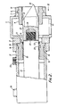
- the device illustrated in Fig 1 comprises a frame 1 which is built up of four hollow frame beams 2 - 5 having a rectangular section, the bevelled outer ends of said frame beams being welded together in the manner illustrated in Fig 1, such that said frame beams 2 - 5 form a square frame which bounds a passage 6.
- a stiffening plate 7 which has a square outer circumference in the illustrated embodiment, and in whose centre there is provided a circular hole which lies in the extension of a hole located in the relevant wall of the hollow frame beam, is provided on that side of each of the frame beams 2 - 5 which bounds the passage 6. Both holes accommodate an elongated bush 8.
- the bush 8 is provided with a projecting collar 9, which butts against the of the plate 7 remote from the frame beam 5, and is clamped against said plate 7 by means of a clamping plate 10, which at its side directed towards the plate 7 is provided with a groove for accommodating the circular rib 9.
- the clamping plate 10 is fixed to the plate 7 by means of four bolts 11, as illustrated in Fig 3.
- a stiffening plate 12 provided with a bore 13, which is located co-axially relative to the central axis of the bores in the stiffening plate 7 accommodating the bush 8 and the web of the beam 5 butting against said stiffening plate 5.
- a cylinder 15 is secured, at its end remote from its closed end, to a mounting plate 16, said mounting plate being provided with a bore accommodating the relevant end of the cylinder 15.
- the plate 16 thereby has a rectangular, square shape, similar to the plate 10, and the plate 16 is fixed to the stiffening plate 12 by means of bolts (not shown).
- the arrangement is thereby such that the central axis of the cylinder 15 coincides with the central axes of the bores 13 and 14 and with the central axes of the bores in the plate 7 and the relevant web of the frame beam 5 accommodating the bush 8.
- a bush 17 is pressed in the end of the cylinder 15 secured to the plate 16, said bush at one end being provided with a projecting circular collar 18, which is accommodated in a correspondingly shaped circular recess in the end of the cylinder 15 and is confined between the stiffening plate 12 and the relevant end of the cylinder 15.
- a projecting nose part 19 of the bush 17 is inserted in the hole 13 provided in the plate 12.
- a guide bush 20 for guiding a piston rod 21 extending in the longitudinal direction of the cylinder 15, said piston rod being secured to a piston (not shown) which is present in the cylinder.
- gaskets or sealing means 22 and 23 surrounding the piston rod 21.
- a circular groove for accommodating a sealing means 24 provided between the outer circumference of the bush 17 and the inner wall of the cylinder 15.
- the cylinder 15 is furthermore provided with stubs 25 and 26 for the connection of pipes intended for the supply and/or discharge of fluid for moving the piston rod 21, with the piston connected thereto, in the longitudinal direction of the cylinder 15.
- the end of the piston rod 21 projecting beyond the bush 17 has a projecting part 27, which has a smaller diameter than the other part of the piston rod 21, and is provided with external screw thread. Said projecting threaded part 27 is screwed in a threaded blind bore 28, which is provided in a cutter 29.
- said cutter has a substantially square cross-section, whilst the cutter, at its end remote from the cylinder 15, tapers into a cutting edge 30, which extends parallel to one of the boundary planes of the cutter, spaced from the longitudinal axis of said cutter, whilst the length of said cutting edge is also slightly less than the width of said cutter, which is the result of the opposed boundary planes of the end of the cutter extending towards the cutting edge 30 in a direction towards one another.
- the diameter of the passage provided in the bush 8 is larger than the distance between two opposed sides of the cutter, but smaller than the distance between two diagonally opposed flattened corner points 31, 32, and 32, 33, respectively, of the cutter.
- a plurality of recesses 36 - 43, extending in the longitudinal direction of the bush 8, are formed between the inner circumference of the guiding passage for the cutter in the bush 8 and the outer circumference of the cutter, said recesses extending between the space 6 enclosed by the frame beams 2 - 5 and the interior of the frame beams in question.
- a hole 44 is provided in the lower boundary wall of each of the frame beams, near the bush 8.
- the above-described device can be moved over a concrete pile 45 in the manner which is also expounded in the above-mentioned US-A-4,480,627, such that said pile will come to lie in the space enclosed by the frame beams 2 - 5. Then said pile can be worked by means of the cutters 29 by moving said cutters to and fro by means of the piston rods 21 and the pistons connected thereto.
- the ring 8 with the cutter and the piston rod 21 connected thereto can be pivoted about the central axis of the piston rod 21, for adjusting the cutting edge 30 in a desired position. It will also be possible to fix the bush 8 relative to the plate 10, after which, for adjusting the cutting edge of the cutter 30 in various positions, the plate 10 can be pivoted through 90° into the one or the other direction, or through 180°, and be fixed again relative to the relevant frame beam.
- the guide bush 8 for the cutter can easily be replaced, if necessary, since it is only necessary to unscrew the plate 10 in order to do so.
- the cylinder 15 can easily be provided and removed by using the above arrangement, so that the device is easy to assemble and disassemble, and worn-out parts or parts which need repair can easily be exchanged.
Landscapes
- Engineering & Computer Science (AREA)
- Life Sciences & Earth Sciences (AREA)
- General Life Sciences & Earth Sciences (AREA)
- Mining & Mineral Resources (AREA)
- Paleontology (AREA)
- Civil Engineering (AREA)
- General Engineering & Computer Science (AREA)
- Structural Engineering (AREA)
- Placing Or Removing Of Piles Or Sheet Piles, Or Accessories Thereof (AREA)
- Earth Drilling (AREA)
- Working Measures On Existing Buildindgs (AREA)
- Crushing And Pulverization Processes (AREA)
Priority Applications (1)
| Application Number | Priority Date | Filing Date | Title |
|---|---|---|---|
| AT89202420T ATE88771T1 (de) | 1988-10-31 | 1989-09-27 | Vorrichtung zum durchtrennen von pfaehlen. |
Applications Claiming Priority (2)
| Application Number | Priority Date | Filing Date | Title |
|---|---|---|---|
| NL8802660 | 1988-10-31 | ||
| NL8802660A NL8802660A (nl) | 1988-10-31 | 1988-10-31 | Inrichting voor het afbreken van palen. |
Publications (2)
| Publication Number | Publication Date |
|---|---|
| EP0367314A1 true EP0367314A1 (de) | 1990-05-09 |
| EP0367314B1 EP0367314B1 (de) | 1993-04-28 |
Family
ID=19853131
Family Applications (1)
| Application Number | Title | Priority Date | Filing Date |
|---|---|---|---|
| EP89202420A Expired - Lifetime EP0367314B1 (de) | 1988-10-31 | 1989-09-27 | Vorrichtung zum Durchtrennen von Pfählen |
Country Status (6)
| Country | Link |
|---|---|
| US (1) | US5025803A (de) |
| EP (1) | EP0367314B1 (de) |
| JP (1) | JPH02266022A (de) |
| AT (1) | ATE88771T1 (de) |
| DE (1) | DE68906240T2 (de) |
| NL (1) | NL8802660A (de) |
Cited By (1)
| Publication number | Priority date | Publication date | Assignee | Title |
|---|---|---|---|---|
| CN104929126A (zh) * | 2015-06-25 | 2015-09-23 | 河北路桥集团有限公司 | 一种桩头破碎装置 |
Families Citing this family (4)
| Publication number | Priority date | Publication date | Assignee | Title |
|---|---|---|---|---|
| US5289816A (en) * | 1992-10-23 | 1994-03-01 | Rakowski Frederick M | Hydraulic ram retraction pile cutter |
| IT1310857B1 (it) * | 1999-10-18 | 2002-02-22 | Mantovanibenne S R L | Dispositivo per la scapitozzatura di pali |
| KR100815836B1 (ko) * | 2007-12-28 | 2008-03-24 | 대원전기 주식회사 | 폴 클램프 및 폴 크러셔를 이용한 배전선로용 콘크리트전주의 무정전 커팅 교체 시공법 |
| FI20125395A7 (fi) * | 2012-04-11 | 2013-10-12 | Motocut Oy | Katkaisulaite ja menetelmä paalun katkaisemiseksi |
Citations (2)
| Publication number | Priority date | Publication date | Assignee | Title |
|---|---|---|---|---|
| US4480627A (en) * | 1982-07-08 | 1984-11-06 | Persluchtcentrale Nederland B.V. | Device for demolishing concrete piles |
| US4756630A (en) * | 1982-05-07 | 1988-07-12 | Teeslink John W | Toolholder guide |
Family Cites Families (1)
| Publication number | Priority date | Publication date | Assignee | Title |
|---|---|---|---|---|
| NL188934C (nl) * | 1984-02-08 | 1992-11-16 | Persluchtcentrale Nederland B | Inrichting voor het afbreken van palen. |
-
1988
- 1988-10-31 NL NL8802660A patent/NL8802660A/nl not_active Application Discontinuation
-
1989
- 1989-09-27 DE DE8989202420T patent/DE68906240T2/de not_active Expired - Fee Related
- 1989-09-27 AT AT89202420T patent/ATE88771T1/de not_active IP Right Cessation
- 1989-09-27 EP EP89202420A patent/EP0367314B1/de not_active Expired - Lifetime
- 1989-10-25 JP JP1276185A patent/JPH02266022A/ja active Pending
- 1989-10-30 US US07/429,113 patent/US5025803A/en not_active Expired - Fee Related
Patent Citations (2)
| Publication number | Priority date | Publication date | Assignee | Title |
|---|---|---|---|---|
| US4756630A (en) * | 1982-05-07 | 1988-07-12 | Teeslink John W | Toolholder guide |
| US4480627A (en) * | 1982-07-08 | 1984-11-06 | Persluchtcentrale Nederland B.V. | Device for demolishing concrete piles |
Non-Patent Citations (1)
| Title |
|---|
| SOVIET INVENTIONS ILLUSTRATED, week 8532, class Q, no. 85-194978/32, 19th September 1985, Derwent Publications Ltd, London, GB; & SU-A-1 086 072 (SKB-MOSSTROIBUREAU), 15th April 1984 * |
Cited By (1)
| Publication number | Priority date | Publication date | Assignee | Title |
|---|---|---|---|---|
| CN104929126A (zh) * | 2015-06-25 | 2015-09-23 | 河北路桥集团有限公司 | 一种桩头破碎装置 |
Also Published As
| Publication number | Publication date |
|---|---|
| DE68906240D1 (de) | 1993-06-03 |
| JPH02266022A (ja) | 1990-10-30 |
| NL8802660A (nl) | 1990-05-16 |
| ATE88771T1 (de) | 1993-05-15 |
| EP0367314B1 (de) | 1993-04-28 |
| US5025803A (en) | 1991-06-25 |
| DE68906240T2 (de) | 1993-08-12 |
Similar Documents
| Publication | Publication Date | Title |
|---|---|---|
| US4686767A (en) | Metal cutting shear for a backhoe | |
| US4670983A (en) | Metal cutting shear and adapter for mounting on a backhoe | |
| EP0170844B1 (de) | Anbohrformstück aus schweissbarem Kunstoff | |
| US4376340A (en) | Material handling and shearing attachment for a backhoe | |
| EP2226164A1 (de) | Roboter mit einer Leitungsführungseinrichtung | |
| US5025803A (en) | Device for breaking off piles | |
| DE2818254B2 (de) | Spreizdübel | |
| EP0209792B1 (de) | Verfahren zur gesteuerten Rückzugsbewegung einer Senkelektrode bei einer Elektroerosionsmaschine | |
| EP0318010B1 (de) | Anschlusselement für eine Betonkragplatte | |
| DE68906273T2 (de) | Vorrichtung zur ausfuehrung von arbeitsvorgaengen in einem rohr. | |
| EP1259340B1 (de) | Sicherheitseinrichtung für eine fertigungsmaschine, z.b. eine abkantpresse | |
| DE20004406U1 (de) | Kniehebelspannvorrichtung, insbesondere zur Verwendung im Karosseriebau der Kfz-Industrie | |
| EP0339261B1 (de) | Einrichtung zur Freilegung der Armierungseisen von Betonpfählen | |
| US20020190092A1 (en) | Method for manufacturing a protective cover for a breaking apparatus, and a breaking apparatus | |
| EP0708270B1 (de) | Schlauchkette | |
| EP0715040B1 (de) | Vorrichtung zum Aufschneiden von Ummantelungen | |
| EP4279659A1 (de) | Schlitzwandgerät und verfahren zum erstellen eines schlitzes im boden | |
| EP1050685B1 (de) | Hydraulischer Linearwegschieber | |
| EP0304407A2 (de) | Freistehender Einwurfschacht für eine Abfallsauganlage | |
| EP0255024B1 (de) | Silagegutschneider mit einem L- oder U-förmigen Tragrahmen | |
| DE10222922A1 (de) | Kaliberplatte mit einem Einsatzteil für eine Formgebungseinrichtung | |
| DE3535490C2 (de) | ||
| CN212682693U (zh) | 一种管梁切断设备 | |
| KR200381253Y1 (ko) | 유압절단기의 가동아암 벌어짐 방지장치 | |
| EP0333729B1 (de) | Rohrkupplung zum anschluss einer rohrabzweigung an ein hauptrohr |
Legal Events
| Date | Code | Title | Description |
|---|---|---|---|
| PUAI | Public reference made under article 153(3) epc to a published international application that has entered the european phase |
Free format text: ORIGINAL CODE: 0009012 |
|
| AK | Designated contracting states |
Kind code of ref document: A1 Designated state(s): AT BE CH DE ES FR GB GR IT LI LU NL SE |
|
| 17P | Request for examination filed |
Effective date: 19901109 |
|
| 17Q | First examination report despatched |
Effective date: 19920123 |
|
| GRAA | (expected) grant |
Free format text: ORIGINAL CODE: 0009210 |
|
| RAP1 | Party data changed (applicant data changed or rights of an application transferred) |
Owner name: KENT AIR EUROPA B.V. |
|
| AK | Designated contracting states |
Kind code of ref document: B1 Designated state(s): AT BE CH DE ES FR GB GR IT LI LU NL SE |
|
| PG25 | Lapsed in a contracting state [announced via postgrant information from national office to epo] |
Ref country code: IT Free format text: LAPSE BECAUSE OF FAILURE TO SUBMIT A TRANSLATION OF THE DESCRIPTION OR TO PAY THE FEE WITHIN THE PRE;WARNING: LAPSES OF ITALIAN PATENTS WITH EFFECTIVE DATE BEFORE 2007 MAY HAVE OCCURRED AT ANY TIME BEFORE 2007. THE CORRECT EFFECTIVE DATE MAY BE DIFFERENT FROM THE ONE RECORDED.SCRIBED TIME-LIMIT Effective date: 19930428 Ref country code: AT Effective date: 19930428 Ref country code: LI Effective date: 19930428 Ref country code: GR Free format text: LAPSE BECAUSE OF FAILURE TO SUBMIT A TRANSLATION OF THE DESCRIPTION OR TO PAY THE FEE WITHIN THE PRESCRIBED TIME-LIMIT Effective date: 19930428 Ref country code: SE Effective date: 19930428 Ref country code: CH Effective date: 19930428 Ref country code: ES Free format text: THE PATENT HAS BEEN ANNULLED BY A DECISION OF A NATIONAL AUTHORITY Effective date: 19930428 |
|
| REF | Corresponds to: |
Ref document number: 88771 Country of ref document: AT Date of ref document: 19930515 Kind code of ref document: T |
|
| REF | Corresponds to: |
Ref document number: 68906240 Country of ref document: DE Date of ref document: 19930603 |
|
| ET | Fr: translation filed | ||
| REG | Reference to a national code |
Ref country code: CH Ref legal event code: PL |
|
| PGFP | Annual fee paid to national office [announced via postgrant information from national office to epo] |
Ref country code: BE Payment date: 19930913 Year of fee payment: 5 |
|
| PGFP | Annual fee paid to national office [announced via postgrant information from national office to epo] |
Ref country code: GB Payment date: 19930917 Year of fee payment: 5 |
|
| PGFP | Annual fee paid to national office [announced via postgrant information from national office to epo] |
Ref country code: FR Payment date: 19930920 Year of fee payment: 5 |
|
| PG25 | Lapsed in a contracting state [announced via postgrant information from national office to epo] |
Ref country code: LU Free format text: LAPSE BECAUSE OF NON-PAYMENT OF DUE FEES Effective date: 19930930 |
|
| PGFP | Annual fee paid to national office [announced via postgrant information from national office to epo] |
Ref country code: DE Payment date: 19930930 Year of fee payment: 5 Ref country code: NL Payment date: 19930930 Year of fee payment: 5 |
|
| PLBE | No opposition filed within time limit |
Free format text: ORIGINAL CODE: 0009261 |
|
| STAA | Information on the status of an ep patent application or granted ep patent |
Free format text: STATUS: NO OPPOSITION FILED WITHIN TIME LIMIT |
|
| 26N | No opposition filed | ||
| PG25 | Lapsed in a contracting state [announced via postgrant information from national office to epo] |
Ref country code: GB Effective date: 19940927 |
|
| PG25 | Lapsed in a contracting state [announced via postgrant information from national office to epo] |
Ref country code: BE Effective date: 19940930 |
|
| BERE | Be: lapsed |
Owner name: KENT AIR EUROPA B.V. Effective date: 19940930 |
|
| PG25 | Lapsed in a contracting state [announced via postgrant information from national office to epo] |
Ref country code: NL Effective date: 19950401 |
|
| NLV4 | Nl: lapsed or anulled due to non-payment of the annual fee | ||
| GBPC | Gb: european patent ceased through non-payment of renewal fee |
Effective date: 19940927 |
|
| PG25 | Lapsed in a contracting state [announced via postgrant information from national office to epo] |
Ref country code: FR Effective date: 19950531 |
|
| PG25 | Lapsed in a contracting state [announced via postgrant information from national office to epo] |
Ref country code: DE Effective date: 19950601 |
|
| REG | Reference to a national code |
Ref country code: FR Ref legal event code: ST |