EP0367347A1 - UHF-Bandpassfilter - Google Patents
UHF-Bandpassfilter Download PDFInfo
- Publication number
- EP0367347A1 EP0367347A1 EP89202737A EP89202737A EP0367347A1 EP 0367347 A1 EP0367347 A1 EP 0367347A1 EP 89202737 A EP89202737 A EP 89202737A EP 89202737 A EP89202737 A EP 89202737A EP 0367347 A1 EP0367347 A1 EP 0367347A1
- Authority
- EP
- European Patent Office
- Prior art keywords
- printed circuit
- filter according
- filter
- resonator
- resonators
- Prior art date
- Legal status (The legal status is an assumption and is not a legal conclusion. Google has not performed a legal analysis and makes no representation as to the accuracy of the status listed.)
- Granted
Links
- 230000001939 inductive effect Effects 0.000 claims description 18
- 239000003990 capacitor Substances 0.000 claims description 9
- 230000008878 coupling Effects 0.000 claims description 9
- 238000010168 coupling process Methods 0.000 claims description 9
- 238000005859 coupling reaction Methods 0.000 claims description 9
- 230000005540 biological transmission Effects 0.000 claims description 6
- 230000005855 radiation Effects 0.000 claims description 4
- 239000000463 material Substances 0.000 claims description 3
- 239000002184 metal Substances 0.000 claims description 3
- 229910052751 metal Inorganic materials 0.000 claims description 3
- 238000005530 etching Methods 0.000 claims description 2
- 238000005192 partition Methods 0.000 claims description 2
- 238000004519 manufacturing process Methods 0.000 description 6
- RYGMFSIKBFXOCR-UHFFFAOYSA-N Copper Chemical compound [Cu] RYGMFSIKBFXOCR-UHFFFAOYSA-N 0.000 description 4
- 229910052802 copper Inorganic materials 0.000 description 4
- 239000010949 copper Substances 0.000 description 4
- 239000004020 conductor Substances 0.000 description 3
- 229910000842 Zamak Inorganic materials 0.000 description 1
- 230000006978 adaptation Effects 0.000 description 1
- 230000002500 effect on skin Effects 0.000 description 1
- 230000007717 exclusion Effects 0.000 description 1
- 238000001914 filtration Methods 0.000 description 1
- 238000000034 method Methods 0.000 description 1
- 238000000465 moulding Methods 0.000 description 1
- 238000010137 moulding (plastic) Methods 0.000 description 1
Images


Classifications
-
- H—ELECTRICITY
- H01—ELECTRIC ELEMENTS
- H01P—WAVEGUIDES; RESONATORS, LINES, OR OTHER DEVICES OF THE WAVEGUIDE TYPE
- H01P1/00—Auxiliary devices
- H01P1/20—Frequency-selective devices, e.g. filters
- H01P1/201—Filters for transverse electromagnetic waves
- H01P1/205—Comb or interdigital filters; Cascaded coaxial cavities
- H01P1/2053—Comb or interdigital filters; Cascaded coaxial cavities the coaxial cavity resonators being disposed parall to each other
Definitions
- the present invention relates to a UHF bandpass filter, comprising at least two resonators each located in a cavity.
- Such filters are well known and used in particular for filtering the various television channels in cable networks.
- the object of the present invention is to eliminate this drawback.
- a bandpass filter is particularly remarkable in that the coupling between input or output and resonator, and between resonators between them is carried out by means of lines drawn on a printed circuit crossing the partitions of the cavities, said lines being arranged in such a way that the transmission of energy between said lines and said resonators takes place exclusively by radiation.
- a filter is also remarkable in that the said cavities are formed by the assembly of two molded half-shells, one of which comprises elements of form such that they each constitute the inductive part of each resonator, the associated capacitor being mounted in sandwich between said inductive element and the bottom of the other half-shell.
- each resonator with a variable capacitor for adjusting the central frequency of the filter, in this case it is advantageous that said inductive elements have a tubular shape and that the adjustable core of each variable capacitor is housed in the hollow of said corresponding tubular element, so that said adjustable core is accessible for adjustment through the tube.
- said coupling printed circuit consists of a semi-rigid material, it is sandwiched in slots made in each half-shell, and said slots are slightly offset to mechanically wedge said printed circuit and jointly ensure ground contacts between the printed circuit and said shells.
- the filter has no welds which reduces manufacturing costs and further guarantees the reproducibility of the quality.
- the UHF band has 45 channels numbered from 21 to 65 for which selectivity standards are imposed (1/300 ⁇ F / F ⁇ 1/30); to obtain this selectivity over the entire band, it is advantageous, all other things being equal, to provide several etchings of the printed circuit, a given etch making it possible to obtain the desired coupling rate for a series of several adjacent channels.
- variable attenuator is mounted on the printed circuit to be able to modify the attenuation of the transmission.
- This attenuator is soldered to the printed circuit but it is located in an additional cavity so that the selectivity of the filter is not affected.
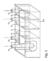
- FIG. 1 represents the lower half-shell (DCI) of the filter of generally elongated rectangular shape comprising four interior walls P1, P2, P3, P4 which delimit five cavities; the extreme cavities include inductive elements S1, S2, S3, S4 which are here tubular, hollow and rough foundry for example in zamac but this is not an obligation: similar shapes would be suitable, as well as a metallized plastic molding surface.
- the interior walls are provided with notches to accommodate the printed circuit (CI) comprising the coupling lines.
- the filter housing also has an upper half-shell (DCS) and the assembly is shown in cross section in Figure 2a; the housing (DCS, DCI) is cut in line with one of the inductive elements (SI) opposite which is a housing (LI); the elements LI and SI are arranged to, during assembly, hold in place a variable capacitor (VOC with dotted line in the figure) whose adjustable core (NA) is engaged in the hollow of the inductive element and thus accessible with a screwdriver according the arrow (TV); to compensate for manufacturing gaps and ensure good electrical contact, an elastic metal washer (RE), for example of the ONDUFLEX type, is provided.
- DCS half-shell
- the upper half-shell obviously has four walls facing the walls P1, P2, P3, P4; they are also indented to create a passage (OP) on the printed circuit; in FIG. 2b the passage (OP) is shown enlarged to show that the notches are slightly offset so that the printed circuit (CI) is clearly deformed and wedged by the half-shells during assembly; thus an electrical contact can be obtained for example at points A and B between the housings and copper lines present at the right of the walls; to fix ideas, the outside diameter of the inductive element is 6 mm and its height is 50 mm, each half-shell is 35 mm high or 70 mm for the filter whose width is 20 mm and the length 90 mm; the central cavity is provided to house the generally used attenuator and, in this case, soldered on the printed circuit.
- Each inductive element (SI) with its associated capacitor (VOC) form an adjustable oscillating circuit; due to the fact that the HF currents propagate by skin effect, that is to say in the case present on the external surface of each inductive element, the momentary introduction of the adjustment screwdriver (TV) inside the tube does not modify not the operation of the oscillating circuit.
- FIG. 3 An example of engraving is shown in Figure 3; the copper lines are represented there either as a line or a hatched area.
- Each circuit has of course the same external dimension, for example 25 ⁇ 90, it is made of semi-rigid material to elastically support the above deformation, only the designs of copper are different from one engraving to another.
- the inductive element S1 with its associated VOC capacitor, has been shown in dotted lines.
- the input signal to be filtered arrives at point EN and, via line L10, it excites the inductive element S1 which reacts with its VOC capacity and in turn excites line L11; energy transmission here takes place exclusively by radiation; the signal collected by L11 is transmitted galvanically by the conductor G1, which crosses the wall P1, to the line L20; the inductive element S2 is excited by the signal present in L20 and, in turn, it excites the line L21; the energy transmission between S2 and L21 is here also exclusively by radiation; the signal is then transmitted by the conductor G2, which crosses the wall P2, to an attenuator connected between the terminals A1 and A2; the signal is then transmitted by the conductor G3, etc ... for, after passing through the walls P3, P4 and by the inductive elements S3 and S4, stand out on the output terminal SO where the filtered signal is available.
Landscapes
- Physics & Mathematics (AREA)
- Electromagnetism (AREA)
- Control Of Motors That Do Not Use Commutators (AREA)
- Filters And Equalizers (AREA)
Applications Claiming Priority (2)
| Application Number | Priority Date | Filing Date | Title |
|---|---|---|---|
| FR8814425 | 1988-11-04 | ||
| FR8814425A FR2638902A1 (fr) | 1988-11-04 | 1988-11-04 | Filtre passe-bande uhf |
Publications (2)
| Publication Number | Publication Date |
|---|---|
| EP0367347A1 true EP0367347A1 (de) | 1990-05-09 |
| EP0367347B1 EP0367347B1 (de) | 1994-04-06 |
Family
ID=9371586
Family Applications (1)
| Application Number | Title | Priority Date | Filing Date |
|---|---|---|---|
| EP89202737A Expired - Lifetime EP0367347B1 (de) | 1988-11-04 | 1989-10-30 | UHF-Bandpassfilter |
Country Status (5)
| Country | Link |
|---|---|
| US (1) | US4990869A (de) |
| EP (1) | EP0367347B1 (de) |
| JP (1) | JPH02172301A (de) |
| DE (1) | DE68914396T2 (de) |
| FR (1) | FR2638902A1 (de) |
Families Citing this family (3)
| Publication number | Priority date | Publication date | Assignee | Title |
|---|---|---|---|---|
| US5543758A (en) * | 1994-10-07 | 1996-08-06 | Allen Telecom Group, Inc. | Asymmetric dual-band combine filter |
| FI110392B (fi) * | 1995-09-26 | 2003-01-15 | Solitra Oy | Koaksiaaliresonaattorisuodatin, koaksiaaliresonaattorisuodattimen valmistusmenetelmä, koaksiaaliresonaattorirakenne ja koaksiaaliresonaattorirakenteen valmistusmenetelmä |
| FI110391B (fi) * | 1995-11-08 | 2003-01-15 | Solitra Oy | Kotelorakenteinen suodatin |
Citations (3)
| Publication number | Priority date | Publication date | Assignee | Title |
|---|---|---|---|---|
| US2519524A (en) * | 1947-08-13 | 1950-08-22 | Hazeltine Research Inc | Multiple-tuned wave-selector system |
| US3693115A (en) * | 1970-12-28 | 1972-09-19 | American Electronic Lab | Mechanical tunable bandpass filter |
| US4740765A (en) * | 1985-09-30 | 1988-04-26 | Murata Manufacturing Co., Ltd. | Dielectric filter |
Family Cites Families (8)
| Publication number | Priority date | Publication date | Assignee | Title |
|---|---|---|---|---|
| DE2045560C3 (de) * | 1970-09-15 | 1978-03-09 | Standard Elektrik Lorenz Ag, 7000 Stuttgart | Mikrowellenfilter aus quaderförmigen Hohlraumresonatoren |
| JPS5924167Y2 (ja) * | 1978-12-28 | 1984-07-18 | アルプス電気株式会社 | マイクロ波用フイルタ |
| US4477785A (en) * | 1981-12-02 | 1984-10-16 | Communications Satellite Corporation | Generalized dielectric resonator filter |
| JPS58114503A (ja) * | 1981-12-26 | 1983-07-07 | Fujitsu Ltd | フイルタの結合構造 |
| US4621245A (en) * | 1984-05-08 | 1986-11-04 | Zenith Electronics Corporation | Intermediate frequency filter for a DBS receiver |
| JPS625702A (ja) * | 1985-07-01 | 1987-01-12 | Fujitsu Ltd | 帯域通過形フイルタ |
| JPS62243402A (ja) * | 1986-04-15 | 1987-10-23 | Murata Mfg Co Ltd | 誘電体フイルタ |
| JPS6324701A (ja) * | 1986-07-16 | 1988-02-02 | Murata Mfg Co Ltd | 分布定数線路装置 |
-
1988
- 1988-11-04 FR FR8814425A patent/FR2638902A1/fr not_active Withdrawn
-
1989
- 1989-10-30 DE DE68914396T patent/DE68914396T2/de not_active Expired - Fee Related
- 1989-10-30 EP EP89202737A patent/EP0367347B1/de not_active Expired - Lifetime
- 1989-11-01 US US07/430,743 patent/US4990869A/en not_active Expired - Fee Related
- 1989-11-02 JP JP1285114A patent/JPH02172301A/ja active Pending
Patent Citations (3)
| Publication number | Priority date | Publication date | Assignee | Title |
|---|---|---|---|---|
| US2519524A (en) * | 1947-08-13 | 1950-08-22 | Hazeltine Research Inc | Multiple-tuned wave-selector system |
| US3693115A (en) * | 1970-12-28 | 1972-09-19 | American Electronic Lab | Mechanical tunable bandpass filter |
| US4740765A (en) * | 1985-09-30 | 1988-04-26 | Murata Manufacturing Co., Ltd. | Dielectric filter |
Non-Patent Citations (4)
| Title |
|---|
| PATENT ABSTRACTS OF JAPAN, vol. 11, no. 171 (E-512)[2618], 2nd juin 1987; & JP-A-62 005 702 (FUJITSU LTD) 12-01-1987 * |
| PATENT ABSTRACTS OF JAPAN, vol. 12, no. 115 (E-599)[2962], 12 avril 1988; & JP-A-62 243 402 (MURATA MFG CO., LTD) 23-10-1987 * |
| PATENT ABSTRACTS OF JAPAN, vol. 12, no. 232 (E-628)[3079], 30 Juin 1988; & JP-A-63 024 701 (MURATA MFG CO., LTD) 02-02-1988 * |
| SIEMENS-BAUTEILE-INFORMATIONEN, vol. 6, no. 6, decembre 1968, pages 200-201, Munich, DE; K. PICHLER et al.: "Vierkreis-UHF-Bandfilter YH AF 1010" * |
Also Published As
| Publication number | Publication date |
|---|---|
| FR2638902A1 (fr) | 1990-05-11 |
| DE68914396T2 (de) | 1994-11-10 |
| DE68914396D1 (de) | 1994-05-11 |
| JPH02172301A (ja) | 1990-07-03 |
| EP0367347B1 (de) | 1994-04-06 |
| US4990869A (en) | 1991-02-05 |
Similar Documents
| Publication | Publication Date | Title |
|---|---|---|
| FR2489605A1 (fr) | Filtre hyperfrequence a resonateur dielectrique, accordable dans une grande largeur de bande, et circuit comportant un tel filtre | |
| FR2583597A1 (fr) | Filtre passe-bande hyperfrequences en mode evanescent | |
| FR2488055A1 (fr) | Transducteur d'antenne pour antenne d'emission-reception et source primaire d'antenne equipee d'un tel transducteur | |
| FR2850793A1 (fr) | Transition entre un circuit micro-ruban et un guide d'onde et unite exterieure d'emission reception incorporant la transition | |
| EP0367347B1 (de) | UHF-Bandpassfilter | |
| EP0260633A1 (de) | Aus verschiedenen Elementen bestehendes Filter der E-Flächenart | |
| FR2750260A1 (fr) | Ensemble d'antenne integree pour une radio et procede de fabrication | |
| EP0281773A1 (de) | Abstimmbares Mikrowellenfilter | |
| EP0112328A1 (de) | Mikrowellenfilterstruktur. | |
| EP0430136A1 (de) | Bandsperrfilter für Mikrowellenhohlleiter | |
| FR2755544A1 (fr) | Dispositif de filtrage a cavite metallique a inserts dielectriques | |
| FR2723801A1 (fr) | Diplexeur a intervalle d'un octave entre bandes. | |
| EP0274950A1 (de) | Breitbandige Kopplungsvorrichtung zwischen der Verzögerungsleitung einer Wanderfeldröhre und der energieübertragenden Aussenschaltung und Wanderfeldröhre mit einer solchen Vorrichtung | |
| EP0738022A1 (de) | Bandpasshohlraumfilter mit Kammleitungsstruktur und Radiohöhenmesser mit einem derartigen Eingangsfilter | |
| FR2704983A1 (fr) | Filtre passe-bande à lignes couplées court-circuitées. | |
| FR2613538A1 (fr) | Filtre hyperfrequence | |
| EP0594502A1 (de) | Abstimmbarer Mikrowellenbandpassfilter mit Zweimodenresonatoren | |
| EP0520919B1 (de) | Filtervorrichtung für elektromagnetische Wellen in einem Wellenleiter mit Rotationssymmetrie, und eingefugten rechteckigen Wellenleiterstücken | |
| EP0072729B1 (de) | Koaxialer Bandsperrfilter | |
| EP2092595A1 (de) | Verfahren zur orthogonalmodus-verbindungskopplung mit mittlerer bis breiter betriebsbandbreite und das verfahren verwendender koppler | |
| JPS6233763B2 (de) | ||
| EP0346806A1 (de) | Bandpassfilter mit dielektrischen Resonatoren | |
| EP0932261A1 (de) | Multiplexer-Demultiplexer für Betrieb in zwei HF-Banden | |
| JPH08293702A (ja) | 有極型コムラインフィルタ | |
| FR2737611A1 (fr) | Dispositif de couplage magnetique entre un conducteur principal d'une ligne tem et un guide d'ondes formant resonateur en lambdag/2 |
Legal Events
| Date | Code | Title | Description |
|---|---|---|---|
| PUAI | Public reference made under article 153(3) epc to a published international application that has entered the european phase |
Free format text: ORIGINAL CODE: 0009012 |
|
| AK | Designated contracting states |
Kind code of ref document: A1 Designated state(s): DE FR GB |
|
| 17P | Request for examination filed |
Effective date: 19901107 |
|
| RAP1 | Party data changed (applicant data changed or rights of an application transferred) |
Owner name: N.V. PHILIPS' GLOEILAMPENFABRIEKEN Owner name: PHILIPS ELECTRONIQUE GRAND PUBLIC |
|
| 17Q | First examination report despatched |
Effective date: 19930528 |
|
| GRAA | (expected) grant |
Free format text: ORIGINAL CODE: 0009210 |
|
| AK | Designated contracting states |
Kind code of ref document: B1 Designated state(s): DE FR GB |
|
| REF | Corresponds to: |
Ref document number: 68914396 Country of ref document: DE Date of ref document: 19940511 |
|
| GBT | Gb: translation of ep patent filed (gb section 77(6)(a)/1977) |
Effective date: 19940630 |
|
| PLBE | No opposition filed within time limit |
Free format text: ORIGINAL CODE: 0009261 |
|
| STAA | Information on the status of an ep patent application or granted ep patent |
Free format text: STATUS: NO OPPOSITION FILED WITHIN TIME LIMIT |
|
| 26N | No opposition filed | ||
| PGFP | Annual fee paid to national office [announced via postgrant information from national office to epo] |
Ref country code: GB Payment date: 19960930 Year of fee payment: 8 |
|
| PGFP | Annual fee paid to national office [announced via postgrant information from national office to epo] |
Ref country code: FR Payment date: 19961022 Year of fee payment: 8 |
|
| PGFP | Annual fee paid to national office [announced via postgrant information from national office to epo] |
Ref country code: DE Payment date: 19961218 Year of fee payment: 8 |
|
| REG | Reference to a national code |
Ref country code: FR Ref legal event code: TP |
|
| PG25 | Lapsed in a contracting state [announced via postgrant information from national office to epo] |
Ref country code: GB Free format text: LAPSE BECAUSE OF NON-PAYMENT OF DUE FEES Effective date: 19971030 |
|
| PG25 | Lapsed in a contracting state [announced via postgrant information from national office to epo] |
Ref country code: FR Free format text: THE PATENT HAS BEEN ANNULLED BY A DECISION OF A NATIONAL AUTHORITY Effective date: 19971031 |
|
| GBPC | Gb: european patent ceased through non-payment of renewal fee |
Effective date: 19971030 |
|
| PG25 | Lapsed in a contracting state [announced via postgrant information from national office to epo] |
Ref country code: DE Free format text: LAPSE BECAUSE OF NON-PAYMENT OF DUE FEES Effective date: 19980701 |
|
| REG | Reference to a national code |
Ref country code: FR Ref legal event code: ST |