EP0367356A1 - Gabelhubwagen mit Vorschubmechanismus - Google Patents
Gabelhubwagen mit Vorschubmechanismus Download PDFInfo
- Publication number
- EP0367356A1 EP0367356A1 EP89202766A EP89202766A EP0367356A1 EP 0367356 A1 EP0367356 A1 EP 0367356A1 EP 89202766 A EP89202766 A EP 89202766A EP 89202766 A EP89202766 A EP 89202766A EP 0367356 A1 EP0367356 A1 EP 0367356A1
- Authority
- EP
- European Patent Office
- Prior art keywords
- mast
- reach
- levers
- forklift
- auxiliary
- Prior art date
- Legal status (The legal status is an assumption and is not a legal conclusion. Google has not performed a legal analysis and makes no representation as to the accuracy of the status listed.)
- Granted
Links
Images


Classifications
-
- B—PERFORMING OPERATIONS; TRANSPORTING
- B66—HOISTING; LIFTING; HAULING
- B66F—HOISTING, LIFTING, HAULING OR PUSHING, NOT OTHERWISE PROVIDED FOR, e.g. DEVICES WHICH APPLY A LIFTING OR PUSHING FORCE DIRECTLY TO THE SURFACE OF A LOAD
- B66F9/00—Devices for lifting or lowering bulky or heavy goods for loading or unloading purposes
- B66F9/06—Devices for lifting or lowering bulky or heavy goods for loading or unloading purposes movable, with their loads, on wheels or the like, e.g. fork-lift trucks
- B66F9/075—Constructional features or details
- B66F9/12—Platforms; Forks; Other load supporting or gripping members
- B66F9/122—Platforms; Forks; Other load supporting or gripping members longitudinally movable
Definitions
- the invention relates to a forklift comprising a frame, which supports a mast, a load bearer with load gripping means such as forks and drive means gripping onto the load bearer for moving the load bearer up and downward along the mast, wherein the load bearer comprises a reach mechanism construction with an auxiliary mast movably guided along the mast, a reach mechanism mast supporting the load gripping means and two pairs of mechanism levers, which each comprise two mechanism levers which are connected with their bottom end in a fixed point of rotation to respectively the auxiliary mast or the reach mechanism mast and with their top end to the other mast in a point of rotation slidable therealong, and which are connected to each other at a pivoting point lying between the ends.
- the load bearer comprises a reach mechanism construction with an auxiliary mast movably guided along the mast, a reach mechanism mast supporting the load gripping means and two pairs of mechanism levers, which each comprise two mechanism levers which are connected with their bottom end in a fixed point of rotation to respectively the auxiliary mast or the reach mechanism mast and
- Such a forklift is per se known.
- the reach mechanism construction serves to be able to pick up or set down a load at a distance from the forklift, for instance when the truck cannot come close enough because of obstacles on the ground, or when work is being carried out with a rack in which pallets are disposed in two rows behind each other.
- a drawback of the known reach mechanism construction is that the carrying capacity of a forklift provided with such a construction is strictly limited.
- the load gripping means are situated at a distance from the main mast, which corresponds with the design reach distance plus the distance which the load gripping means already have in relation to the main mast in the retracted position of the reach mechanism construction, as a result of the space taken up thereby.
- the invention has for its object to provide a forklift of the sort described in the preamble wherein the carrying capacity, taking into account the design reach distance, is as great as possible.
- An additional advantage of the forklift according to the invention is that in the retracted position of the reach mechanism construction a load on the load bearer is situated as closely as possible to the main mast, so that driving the forklift according to the invention with a load involves no greater danger of tipping over than is the case with a similar forklift without reach mechanism construction.
- a further important advantage of the invention is that the reach mechanism construction in the retracted position thereof does not increase the total length of the forklift. This is particularly important for transportable forklifts, which are carried behind a truck. In accordance with traffic regulations such a transportable forklift qualifies as a load protruding behind the truck. Stringent limitations are applied to the distance over which a load may protrude.
- a further improvement of the torsional stiffness is obtained when according to the invention the pivoting points of the pairs of mechanism levers are mutually connected for torsional stiffness by a connecting shaft.
- a favourable embodiment of the forklift according to the invention is characterized in claim 4.
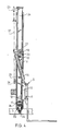
- the forklift 1 shown in the figures comprises a frame 2 which can drive over a ground surface by means of wheels 3 connected thereto.
- the forklift 1 is of the transportable type, wherein the front wheels 3 normally lie at a distance in front of the mast construction 4, so that the centre of gravity of a transported load lies within the support surface defined by the wheels. No counter weight is hereby necessary and the forklift can therefore take a light form.
- load bearer 5 which is provided with load gripping means such as forks 6.
- Drive means here in the form of piston cylinder devices 7, grip onto the load bearer to move the load bearer 5 up and downward along the mast 4.
- the load bearer 5 comprises a reach mechanism construction here generally designated by 8, which makes it possible to displace the lifting forks 6 between a retracted position, wherein the lifting forks are situated close to the mast 4, and an extended position, as shown in fig. 1.
- the reach mechanism construction 8 is operated using a piston cylinder device 15.
- the lifting forks 6 can be moved to a position in front of the front wheels 3, by extending the reach mechanism construction 8.
- the lifting forks 6 can thus be inserted into a pallet on the carrying floor of the truck and this pallet can be picked up, even when the wheels 3 cannot travel beneath the truck because for instance a wheel of the truck is situated at that location.
- the reach mechanism construction 8 comprises an auxiliary mast 23 guided movably along the main mast 4, a reach mechanism mast 22 supporting the load gripping means 6 and two pairs of mechanism levers, each comprising two mechanism levers 9, 10.
- the mechanism levers 9 are connected with their bottom ends to the auxiliary mast 23 in a fixed point of rotation 11, while the mechanism levers 10 are connected with their bottom ends to the reach mechanism mast 22 in a fixed point of rotation 12.
- the main mast 4 As can be seen from the figures the main mast 4, the auxiliary mast 23 and the reach mechanism mast 22 are each assembled from two pillars placed at a mutual distance.
- the top ends of the levers 9 and 10 are connected respectively to the reach mechanism mast 22 and the auxiliary mast 23 by means of a point of rotation slidable along the relevant mast.
- the main mast 4 comprises an outer mast 25 connected to the frame and an inner mast 24 slidable therein.
- the auxiliary mast 23 is again mounted slidably in the inner mast 24 by means of rollers 31, 32.
- the piston cylinder devices 7 are connected with a bottom end to the outer mast 25 and with their top end to a beam connecting the inner masts 24.
- On either side at the top and bottom the inner mast 24 supports the respective pulleys 26 and 28.
- a cable 27 is tensioned around each pair of associated pulleys 26 and 28.
- the outer portion of the cable 27 is fixedly connected in each case to the outer mast 25, close to the top end thereof.
- the inner portion of the cable 27 is connected in each case to the auxiliary mast 23, close to the top end thereof.
- the top ends of the pairs of mechanism levers 9 and 10 are in each case connected to each other in torsion stiff manner by the respective connecting shafts 19 and 18.
- the ends of these shafts carry rollers slidable in the respective reach mechanism mast 22 and auxiliary mast 23.
- the bottom ends of the mechanism levers 9 are likewise connected to each other in torsion stiff manner by means of a connecting shaft 18.
- the ends of this connecting shaft are mounted rotatably in the auxiliary mast 23 and in the line thereof rollers 31 are arranged, by means of which the auxiliary mast 23 can be moved in the inner mast 24.
- rollers 32 Arranged at the top end of the auxiliary mast 23 are corresponding rollers 32.
- the mechanism levers 9 and 10 are rotatably connected to each other in a pivoting point 16.
- the levers 9 are mutually connected in the pivoting point 16 in torsion stiff manner by the connecting shaft 20, while the levers 10 are rotatably mounted on the extension of this shaft 20.
- each mechanism lever 9, 10 is provided out of the centre between the points of rotation at the ends.
- the distance between the point of rotation 12 and the pivoting point 16 is smaller than the distance between the point of rotation 13 and the pivoting point 16 of the lever 10.
- the distance between the point of rotation 14 and the pivoting point 16 is smaller than the distance between the point of rotation 11 and the pivoting point 16 of the levers 9.
- the stated distances of the respective levers 9 and 10 are in each case equal on the same side of the pivoting point 16. For good operation, that is, a guiding such that the reach mechanism mast 22 remains in each case parallel to the auxiliary mast 23, it is sufficient that only the ratio of these distances is equal in each lever.
- the respective pillars of the reach mechanism mast 22 are disposed at a distance such that in the folded in state the outer mechanism levers 10 again fall inside them.
- the pillars of the auxiliary mast 23 are again placed at a distance such that the pillars of the reach mechanism mast 20 again fall between them.
- the whole reach mechanism construction therefore falls in the retracted position at least virtually within the space defined by the outer mast 25 of the main mast 4.
- the mast construction according to the invention can be used in combination with a so-called "side shift".
- this comprises a transverse guide bar 36 arranged in the frame and on which the mast construction rests using wheels 33.
- These wheels 33 are mounted in a beam fixedly connected to the outer mast 25. This construction is per se known and will not be further described in detail.
Landscapes
- Engineering & Computer Science (AREA)
- Transportation (AREA)
- Structural Engineering (AREA)
- Civil Engineering (AREA)
- Life Sciences & Earth Sciences (AREA)
- Geology (AREA)
- Mechanical Engineering (AREA)
- Forklifts And Lifting Vehicles (AREA)
Applications Claiming Priority (2)
| Application Number | Priority Date | Filing Date | Title |
|---|---|---|---|
| NL8802712 | 1988-11-04 | ||
| NL8802712A NL8802712A (nl) | 1988-11-04 | 1988-11-04 | Vorkhefwagen met reikschaar. |
Publications (2)
| Publication Number | Publication Date |
|---|---|
| EP0367356A1 true EP0367356A1 (de) | 1990-05-09 |
| EP0367356B1 EP0367356B1 (de) | 1993-04-07 |
Family
ID=19853171
Family Applications (1)
| Application Number | Title | Priority Date | Filing Date |
|---|---|---|---|
| EP19890202766 Expired - Lifetime EP0367356B1 (de) | 1988-11-04 | 1989-11-02 | Gabelhubwagen mit Vorschubmechanismus |
Country Status (3)
| Country | Link |
|---|---|
| EP (1) | EP0367356B1 (de) |
| DE (1) | DE68905899T2 (de) |
| NL (1) | NL8802712A (de) |
Cited By (7)
| Publication number | Priority date | Publication date | Assignee | Title |
|---|---|---|---|---|
| NL9400340A (nl) * | 1994-03-04 | 1995-10-02 | Blom R Beheer Bvr | Reikinrichting voor het in een richting dwars op een hefmast, translerend verplaatsen van een last. |
| US7001131B2 (en) | 2003-03-14 | 2006-02-21 | Moffett Research And Development Limited | Forklift loading support |
| NL1030868C2 (nl) * | 2006-01-06 | 2007-07-09 | Quick Group B V | Inrichting en werkwijze voor het heffen van lasten. |
| WO2014120742A1 (en) * | 2013-02-04 | 2014-08-07 | Crown Equipment Corporation | Reach assembly with improved operator visibility for a materials handling vehicle |
| CN105365868A (zh) * | 2015-11-30 | 2016-03-02 | 湖州优创科技有限公司 | 一种实木地板用木材烘干搬运车 |
| CN110758501A (zh) * | 2019-10-31 | 2020-02-07 | 如皋市宝象叉车有限公司 | 一种便携式电动手推车 |
| CN114537493A (zh) * | 2022-03-01 | 2022-05-27 | 南京晓庄学院 | 一种具有适用环境影响功能的工程机械转移装置 |
Citations (8)
| Publication number | Priority date | Publication date | Assignee | Title |
|---|---|---|---|---|
| US2752058A (en) * | 1953-07-22 | 1956-06-26 | Raymond Corp | Material handling lift truck |
| DE1134029B (de) * | 1959-02-10 | 1962-07-26 | Steinbock G M B H | Hublader mit einem mittels Scheren vorschiebbaren Lasttraeger |
| US3048293A (en) * | 1960-09-16 | 1962-08-07 | Walton W Cushman | Side-loading counterbalanced industrial lift truck |
| US3082894A (en) * | 1960-06-09 | 1963-03-26 | Raymond Corp | Lift truck reach mechanism |
| US3219210A (en) * | 1963-09-06 | 1965-11-23 | Steinbock Gmbh | Mast assembly for a side loading truck |
| GB1030788A (en) * | 1962-12-06 | 1966-05-25 | Aloysius Thedorus Van Huet | A transporting device for a stack of bricks for mounting on a fork-lift truck |
| FR1509609A (fr) * | 1966-01-27 | 1968-01-12 | Dso Balkancar | Chariot électrique élévateur à grande levée |
| US3757977A (en) * | 1971-09-30 | 1973-09-11 | Brudi Equipment | Tote pan handler attachment for lift trucks |
-
1988
- 1988-11-04 NL NL8802712A patent/NL8802712A/nl not_active Application Discontinuation
-
1989
- 1989-11-02 EP EP19890202766 patent/EP0367356B1/de not_active Expired - Lifetime
- 1989-11-02 DE DE1989605899 patent/DE68905899T2/de not_active Expired - Fee Related
Patent Citations (8)
| Publication number | Priority date | Publication date | Assignee | Title |
|---|---|---|---|---|
| US2752058A (en) * | 1953-07-22 | 1956-06-26 | Raymond Corp | Material handling lift truck |
| DE1134029B (de) * | 1959-02-10 | 1962-07-26 | Steinbock G M B H | Hublader mit einem mittels Scheren vorschiebbaren Lasttraeger |
| US3082894A (en) * | 1960-06-09 | 1963-03-26 | Raymond Corp | Lift truck reach mechanism |
| US3048293A (en) * | 1960-09-16 | 1962-08-07 | Walton W Cushman | Side-loading counterbalanced industrial lift truck |
| GB1030788A (en) * | 1962-12-06 | 1966-05-25 | Aloysius Thedorus Van Huet | A transporting device for a stack of bricks for mounting on a fork-lift truck |
| US3219210A (en) * | 1963-09-06 | 1965-11-23 | Steinbock Gmbh | Mast assembly for a side loading truck |
| FR1509609A (fr) * | 1966-01-27 | 1968-01-12 | Dso Balkancar | Chariot électrique élévateur à grande levée |
| US3757977A (en) * | 1971-09-30 | 1973-09-11 | Brudi Equipment | Tote pan handler attachment for lift trucks |
Cited By (11)
| Publication number | Priority date | Publication date | Assignee | Title |
|---|---|---|---|---|
| NL9400340A (nl) * | 1994-03-04 | 1995-10-02 | Blom R Beheer Bvr | Reikinrichting voor het in een richting dwars op een hefmast, translerend verplaatsen van een last. |
| US7001131B2 (en) | 2003-03-14 | 2006-02-21 | Moffett Research And Development Limited | Forklift loading support |
| NL1030868C2 (nl) * | 2006-01-06 | 2007-07-09 | Quick Group B V | Inrichting en werkwijze voor het heffen van lasten. |
| EP1806312A2 (de) | 2006-01-06 | 2007-07-11 | Quick Group B.V. | Vorrichtung und Verfahren um Lasten zu Heben |
| EP1806312A3 (de) * | 2006-01-06 | 2007-07-18 | Quick Group B.V. | Vorrichtung und Verfahren um Lasten zu Heben |
| WO2014120742A1 (en) * | 2013-02-04 | 2014-08-07 | Crown Equipment Corporation | Reach assembly with improved operator visibility for a materials handling vehicle |
| WO2014120726A1 (en) * | 2013-02-04 | 2014-08-07 | Crown Equipment Corporation | Reach assembly with offset pivot points for a materials handling vehicle |
| CN105050936A (zh) * | 2013-02-04 | 2015-11-11 | 克朗设备公司 | 用于物料搬运车辆的具有改进的操作者可见度的前伸组件 |
| CN105365868A (zh) * | 2015-11-30 | 2016-03-02 | 湖州优创科技有限公司 | 一种实木地板用木材烘干搬运车 |
| CN110758501A (zh) * | 2019-10-31 | 2020-02-07 | 如皋市宝象叉车有限公司 | 一种便携式电动手推车 |
| CN114537493A (zh) * | 2022-03-01 | 2022-05-27 | 南京晓庄学院 | 一种具有适用环境影响功能的工程机械转移装置 |
Also Published As
| Publication number | Publication date |
|---|---|
| DE68905899T2 (de) | 1993-07-15 |
| DE68905899D1 (de) | 1993-05-13 |
| EP0367356B1 (de) | 1993-04-07 |
| NL8802712A (nl) | 1990-06-01 |
Similar Documents
| Publication | Publication Date | Title |
|---|---|---|
| CA1113891A (en) | Forklift vehicle | |
| US4065012A (en) | Low lift truck | |
| US3727778A (en) | Material handling system | |
| US3295881A (en) | Cargo carrier for load-handling systems | |
| US3998346A (en) | Material handling apparatus | |
| US4995774A (en) | Side-loading fork lift vehicle | |
| US2910204A (en) | Industrial lift truck | |
| GB2104052A (en) | Handling storage units, e.g. pallets | |
| US3092268A (en) | Industrial lift truck | |
| EP0367356A1 (de) | Gabelhubwagen mit Vorschubmechanismus | |
| US3713556A (en) | Lifting apparatus | |
| US3672526A (en) | Front and side loading attachment for lifting trucks | |
| US4526504A (en) | Push-pull de-tiering system | |
| US2601932A (en) | Means for handling material | |
| US4400130A (en) | Method and apparatus for handling and transporting a load | |
| CA1044187A (en) | Lift truck mast positioning mechanism | |
| DE1060789B (de) | Hupstapler mit verschiebbarem Mast und einer Plattform zum Ablegen des Ladegutes | |
| CA1080159A (en) | Bundle carrier attachment for fork lift trucks | |
| US3599818A (en) | Load support attachment for vertical lift trucks providing horizontal and rotational displacement of a load | |
| DE3328241C2 (de) | Förderfahrzeug | |
| EP0553067B1 (de) | Gabelhubwagen | |
| US3785515A (en) | Transverse-traveling load handling vehicle | |
| EP0086665A1 (de) | Fördervorrichtung | |
| CN214192440U (zh) | 一种集装箱车装卸搬运小车 | |
| US5030055A (en) | Physically integrated manufacturing and materials handling system |
Legal Events
| Date | Code | Title | Description |
|---|---|---|---|
| PUAI | Public reference made under article 153(3) epc to a published international application that has entered the european phase |
Free format text: ORIGINAL CODE: 0009012 |
|
| AK | Designated contracting states |
Kind code of ref document: A1 Designated state(s): BE DE FR GB NL |
|
| 17P | Request for examination filed |
Effective date: 19900625 |
|
| 17Q | First examination report despatched |
Effective date: 19910814 |
|
| GRAA | (expected) grant |
Free format text: ORIGINAL CODE: 0009210 |
|
| AK | Designated contracting states |
Kind code of ref document: B1 Designated state(s): BE DE FR GB NL |
|
| REF | Corresponds to: |
Ref document number: 68905899 Country of ref document: DE Date of ref document: 19930513 |
|
| ET | Fr: translation filed | ||
| PLBI | Opposition filed |
Free format text: ORIGINAL CODE: 0009260 |
|
| 26 | Opposition filed |
Opponent name: CANGARU FORKLIFT B.V. Effective date: 19940107 |
|
| NLR1 | Nl: opposition has been filed with the epo |
Opponent name: CANGARU FORKLIFT B.V. |
|
| PLAB | Opposition data, opponent's data or that of the opponent's representative modified |
Free format text: ORIGINAL CODE: 0009299OPPO |
|
| R26 | Opposition filed (corrected) |
Opponent name: CANGARU FORKLIFT B.V. Effective date: 19940107 |
|
| PLBN | Opposition rejected |
Free format text: ORIGINAL CODE: 0009273 |
|
| STAA | Information on the status of an ep patent application or granted ep patent |
Free format text: STATUS: OPPOSITION REJECTED |
|
| 27O | Opposition rejected |
Effective date: 19951016 |
|
| NLR2 | Nl: decision of opposition | ||
| NLS | Nl: assignments of ep-patents |
Owner name: KOOI B.V. |
|
| REG | Reference to a national code |
Ref country code: FR Ref legal event code: TP |
|
| REG | Reference to a national code |
Ref country code: GB Ref legal event code: 732E |
|
| REG | Reference to a national code |
Ref country code: GB Ref legal event code: IF02 |
|
| PGFP | Annual fee paid to national office [announced via postgrant information from national office to epo] |
Ref country code: GB Payment date: 20031104 Year of fee payment: 15 |
|
| PGFP | Annual fee paid to national office [announced via postgrant information from national office to epo] |
Ref country code: FR Payment date: 20031128 Year of fee payment: 15 Ref country code: DE Payment date: 20031128 Year of fee payment: 15 Ref country code: BE Payment date: 20031128 Year of fee payment: 15 |
|
| PGFP | Annual fee paid to national office [announced via postgrant information from national office to epo] |
Ref country code: NL Payment date: 20031130 Year of fee payment: 15 |
|
| PG25 | Lapsed in a contracting state [announced via postgrant information from national office to epo] |
Ref country code: GB Free format text: LAPSE BECAUSE OF NON-PAYMENT OF DUE FEES Effective date: 20041102 |
|
| PG25 | Lapsed in a contracting state [announced via postgrant information from national office to epo] |
Ref country code: BE Free format text: LAPSE BECAUSE OF NON-PAYMENT OF DUE FEES Effective date: 20041130 |
|
| BERE | Be: lapsed |
Owner name: *KOOI B.V. Effective date: 20041130 |
|
| PG25 | Lapsed in a contracting state [announced via postgrant information from national office to epo] |
Ref country code: NL Free format text: LAPSE BECAUSE OF NON-PAYMENT OF DUE FEES Effective date: 20050601 Ref country code: DE Free format text: LAPSE BECAUSE OF NON-PAYMENT OF DUE FEES Effective date: 20050601 |
|
| GBPC | Gb: european patent ceased through non-payment of renewal fee |
Effective date: 20041102 |
|
| PG25 | Lapsed in a contracting state [announced via postgrant information from national office to epo] |
Ref country code: FR Free format text: LAPSE BECAUSE OF NON-PAYMENT OF DUE FEES Effective date: 20050729 |
|
| NLV4 | Nl: lapsed or anulled due to non-payment of the annual fee |
Effective date: 20050601 |
|
| REG | Reference to a national code |
Ref country code: FR Ref legal event code: ST |
|
| BERE | Be: lapsed |
Owner name: *KOOI B.V. Effective date: 20041130 |
|
| PLAB | Opposition data, opponent's data or that of the opponent's representative modified |
Free format text: ORIGINAL CODE: 0009299OPPO |