EP0367368A1 - Bahnführungsvorrichtung - Google Patents
Bahnführungsvorrichtung Download PDFInfo
- Publication number
- EP0367368A1 EP0367368A1 EP89303909A EP89303909A EP0367368A1 EP 0367368 A1 EP0367368 A1 EP 0367368A1 EP 89303909 A EP89303909 A EP 89303909A EP 89303909 A EP89303909 A EP 89303909A EP 0367368 A1 EP0367368 A1 EP 0367368A1
- Authority
- EP
- European Patent Office
- Prior art keywords
- web
- operator
- guidance system
- control
- edge
- Prior art date
- Legal status (The legal status is an assumption and is not a legal conclusion. Google has not performed a legal analysis and makes no representation as to the accuracy of the status listed.)
- Granted
Links
Images













Classifications
-
- B—PERFORMING OPERATIONS; TRANSPORTING
- B65—CONVEYING; PACKING; STORING; HANDLING THIN OR FILAMENTARY MATERIAL
- B65H—HANDLING THIN OR FILAMENTARY MATERIAL, e.g. SHEETS, WEBS, CABLES
- B65H23/00—Registering, tensioning, smoothing or guiding webs
- B65H23/02—Registering, tensioning, smoothing or guiding webs transversely
- B65H23/0204—Sensing transverse register of web
- B65H23/0216—Sensing transverse register of web with an element utilising photoelectric effect
-
- B—PERFORMING OPERATIONS; TRANSPORTING
- B65—CONVEYING; PACKING; STORING; HANDLING THIN OR FILAMENTARY MATERIAL
- B65H—HANDLING THIN OR FILAMENTARY MATERIAL, e.g. SHEETS, WEBS, CABLES
- B65H23/00—Registering, tensioning, smoothing or guiding webs
- B65H23/02—Registering, tensioning, smoothing or guiding webs transversely
- B65H23/032—Controlling transverse register of web
- B65H23/038—Controlling transverse register of web by rollers
Definitions
- This invention relates generally to web handling apparatus and more particularly to a microprocessor controlled web guidance system to automatically implement and maintain proper lateral web alignment of a continuous web in a web handling system such as a printing press.
- operations are performed in a continuous travelling web of a thin material, such as paper or plastic film, etc., which move through machines at high speed.
- Such web process operations include, for example, printing of newspapers or magazines, coating the moving web, slitting the moving web lengthwise, cutting the moving web transversely, etc. These operations usually require accurate lateral alignment of the web to maintain the web in proper registry with the machine that operates on the web.
- web guide apparatus which includes a stationary support frame with a moveable steering frame mounted on the support frame.
- This moveable frame is steered by an appropriate positioning device such as a hydraulic cylinder or an electric motor, and normally includes a pair of spaced, parallel steering rollers over which the web is run.
- a sensor detects the lateral position of the web as it leaves the steering rollers and generates a signal to control the steering frame positioning motor.
- the moveable steering frame is pivoted relative to the support frame by the positioning motor about a pivot point along the center line axis of the incoming web. This pivoting action moves the rollers such that the web is repositioned laterally as it moves along and over the guide rollers.
- the sensing of the alignment of the moving head is accomplished by using a single web edge detector, such as a photodetector or infrared detector, positioned at one lateral edge of the moving web to detect transverse displacement of the web edge.
- a single web edge detector such as a photodetector or infrared detector
- the width of the moving web may vary so that two edge detectors have been used to monitor both edges of the web.
- moveable edge detectors have been used in the prior art. Systems have also been proposed which provide a digital readout display of the correction being made to the position of the web.
- Prior art web guide systems have numerous deficiencies. Such systems do not provide diagnostic and maintenance modes of operation to aide in the operation of the apparatus. Inability to calibrate the tilt mechanism makes it difficult to set trip points to stop or adjust the web handling line. These limitations often lead to undesirable and expensive crashes of the web handling line. In addition, control and drive mechanisms for the movement of the edge sensors has been inadequate leading to failure to keep track of sensor position and inaccurate position of the sensor due to gear backlash.
- the present invention overcomes these and other deficiencies of the prior art web guide apparatus and provides new and additional features not heretofore available.
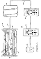
- FIG. 1 there is shown a diagrammatic illustration of a web guide system 20 in accordance with the present invention for use with a web printing press.
- the system 20 includes a web guide assembly 22, control circuitry 24, a control panel 26, an optional remote control panel 28, and an optional auxiliary control panel 30.
- the web guide assembly 22 is shown with a front view having a top roller 32, which forms the exit roller of the steering or tilt mechanism, shown in more detail in FIG. 3A, and having a lower roller 34, functioning as an exit roller.
- the rollers 32 and 34 are mounted on a stationary frame composed of a gear edge plate 36 and an operator edge plate 38.
- a scanner mechanism 80 having two edge sensors 82, 84 is mounted to the gear edge plate 36 and operator edge plate 38, as shown.
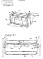
- FIG. 2 is a perspective view of the web guide assembly 22 with portions removed to illustrate a specific example of the travel of the web 40 through the assembly 22.
- the web 40 is threaded from an idler entrance roller 42 over an lead-in steering roller 44 and the exit steering roller 32 and under the exit idler roller 44, as shown.
- the steer- . ing rollers 32 and 44 form a steering mechanism 50, and are rotatably mounted on the steering roller support members 46, 48.
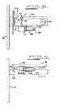
- FIG. 3A is a top view of the steering assembly 50, with the drive mechanism removed, having the side members 46, 48 mounted on a steering pivot beam 52.
- the pivot beam 52 is mounted on a support cross-member 54 (See Figure 1 and Figure 3B) by means of a pivot mechanism 56.
- the support cross-member 54 is mounted on the stationary frame side plates 36, 38 as shown in Figure 1.
- the pivot mechanism allows the steering assembly 50 composed of the lead-in and exit steering rollers 44, 32, the side members 46, 48, and the pivot beam 52 to be angularly pivoted (tilted) about the axis of the pivot mechanism 56 in the directions shown by the arrows 58, 60 relative to the support cross-member 54.
- An offset center pivot is utilized with the pivot 56 offset toward the lead-in side of the steering mechanism 50 to provide the greatest web movement as a function of pivot position with respect to minimum web distortion. The offset also pushes the web in the direction of the correction thereby yielding a faster correction rate.
- a tilt potentiometer 78 is also coupled to the steering mechanism 50 by a coupling mechanism 79 and mounted on the support cross member 54. The tilt potentiometer 78 provides a position signal which permits the control circuitry 24 to monitor the relative position of the steering pivot beam 52.
- the pivot beam 52 is driven angularly in either direction by a drive means including a DC motor 62, as shown in the top view of a portion of the steering mechanism 50 illustrated in Figure 3B.
- the motor 62 includes a tachometer 64, and is coupled to a gear box 56 mounted on the support cross-member 54.
- a lead screw gear assembly 68 extending from the gear box 66 and driven by the motor 62 drives the pivot beam 52 to the desired angular position by interaction with a ball bearing nut assembly 70 mounted on the pivot beam 52, as shown.
- the tachometer 52 permits the system control circuitry 24 to monitor the speed at which the beam is pivoted and uses this signal as a feedback signal to aid in controlling the correction motor 62.
- Limit switches 72, 74 mounted on the support cross-member 54 interact with a paddle 76 to provide a limit signal to the control circuitry 24 when the pivot beam 52 reaches maximum permitted angular displacement.
- the structure of the steering assembly 50 may be more fully appreciated by inspection of the side view of a portion of the steering mechanism illustrated in Figure 3C.
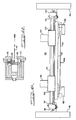
- FIG. 4A there is illustrated a top view of a specific embodiment of the scanner mechanism 80 shown in Figure 1.
- the scanner mechanism 80 is mounted on the operator edge support plate 38 and gear edge support plate 36 of the stationary support frame, as shown.
- the scanner mechanism includes two movable edge sensors, an operator edge sensor 82 and a gear edge sensor 84 movably mounted on a scanner bar 86.
- the edge sensors 82, 84 are also coupled to drive means comprising an operator sensor synchronous stepper motor 88 and a gear sensor synchronous stepper motor 90 which are movably mounted to engage a linear cogged belt 92.
- This structure enables backlash free movement of the sensors 82, 84 by the independent stepper motors 88, 90 while ensuring accurate location of the sensors.
- the stepper motors 88, 90 are controlled by signals coupled from the control logic 24.
- An operator side tensioner 94 is provided, as shown, to ensure proper tension of the belt 92.
- An operator end of travel block 98 and gear end of travel block 100 interact with end of travel sensors 102 and 104, respectively, to provide end of travel signals to the control circuitry 24.
- edge sensors 82, 84 The operation of the edge sensors 82, 84 is illustrated in the diagrammatic cross sectional top view of an edge sensor in FIG. 4B.
- Each sensor is constructed having two separated arm portions 110 and 112, as shown.
- a source of radiation 114 emitting infrared light in the illustrated embodiment.
- the infrared light emitted by the source 114 is modulated by a 2KHz modulating signal in the illustrated embodiment to mask out ambient light.
- a transparent cover 116 is mounted, as shown, and the infrared light radiates through the cover 116 into a channel having a width which encompasses the typical range of web edge deviation from a desired or predetermined position.
- a detector 120 such as an infrared photocell, receives the infrared radiation and produces an input signal corresponding to the magnitude of the infrared radiation impinging upon the detector 120. As shown, the sensor is positioned such that the web blocks part of the light path. Thus, the amount of infrared radiation block is directly proportional to the web position and the signal generated by the detector 120 is directly related to the web position.
- Two sensors are supplied with the system to permit several types of operation.
- the system When guiding in the center mode using two sensors the system essentially compares the output of both sensors and adjusts the steering mechanism to position the web such that the signal from both sensors is equal.
- edge guiding the system compares the output of the selected sensor with a preset constant. This preset constant is set such that the steering mechanism positions the web in the middle of the sensor. In the center mode using both sensors, the centerline of the web is what the system accurately holds in position. In the edge mode, the edge selected is the side the system holds accurately.
- the web guide assembly 22, including the steering mechanism motor 62 and the sensor motors 88, 90 is controlled by control signals coupled via a junction block 120 and a cable 122 to the web guide assembly 22 from the control circuitry 24, as shown in FIG. 1, to provide control of the course of the web 40, either automatically or manually.
- the control circuitry 24 is described in greater detail hereinafter with reference to FIGS. 7 and 9.
- Operator control of the circuitry is provided by a control panel 26, and optional additional control panels including a number of additional remote panels 28 and auxiliary control 30, as shown.
- the control panels 26 and 28, are identical and permit operator control of the web guidance system 20 while the auxiliary control permits manual adjustment of the steering mechanism 50.
- the control panels 26, 28, 30 are connected in parallel and utilize a serial, full duplex communications protocol to communicate via a cable 124 with the control circuitry 24.
- the control panel circuitry is described in detail hereinafter with reference to FIG. 8.
- control panel 26 which operates in conjunction with the control panel circuitry shown in FIG. 8, the control circuitry shown in FIG. 7, and the edge sensors, end of travel sensor, limit switches, motors, and other devices that control the web guide assembly to perform the functional operation selected by the control panel 26.
- the control panel 26 includes an eight character alphanumeric readout display 130 capable of displaying or scrolling alphabetic or numeric characters.
- the control panel also includes guide mode indicators 132, 134, motor direction indicators 133, 135 and various panel keys.
- the panel keys include a program mode (PGM) key 136, a select (SEL) key 138, and operator correction (-) key 140, a gear correction (+) key 142, a manual mode key 144, an auto mode key 146, and a center mode key 148, as shown.
- PGM program mode
- SEL select
- - operator correction
- - gear correction
- a manual mode key 144 a manual mode key
- an auto mode key 146 an auto mode key
- center mode key 148 a center mode key 148
- Each of the Manual, Auto and Center keys has an associated indicator lamp (e.g., an LED in the illustrated embodiment), as shown, to indicate when the key is activated.
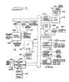
- FIG. 6 is flow diagram illustrating the functional flow and methodology of a program for the microprocessor of the system control circuitry 24 in accordance with the invention, and illustrates the five primary functional modes.
- the five primary functional modes of the system operation are MANUAL, AUTO, CENTER, PROGRAM and MAINTENANCE modes.
- a program listing for the process illustrated in FIG. 6 for the control circuitry processor (Z-80) of the illustrated embodiment is provided in Appendix A attached hereto.
- the system upon power up initializes to default values stored in memory if the PZ switch is held on, and otherwise retains values set during previous operation, as illustrated at block 160. Also, as illustrated at block 160, upon powerup the system automatically enters the manual mode by branching to block 162, as shown. While in any mode, the system continually checks for panel key depressions to enable the system to respond to the control panel key selections made by the operator. In the manual mode, the steering mechanism 50 pivot beam 52 may be moved using the operator correction key 140 and the gear correction key 142, as illustrated at block 164. Thus, the web can be shifted in the operator direction by use of the operator key 140 and in the gear direction by depressing the gear key 142.
- the readout during this mode will monitor and display the current steering beam tilt in a gear or operator percentage or will display "00 CNTR" for the condition in which the steering beam is perfectly centered, as illustrated by block 166.
- the message "LIMIT” will flash in the readout display 130 whenever an operator or gear tilt limit occurs and the corresponding correction indicator will also flash. This condition will remain until the steering beam is moved off of the limit.
- the manual mode may be selected while in any of the other modes, and the edge sensors will retract during the manual mode if they are not already fully retracted. As illustrated at block 168, the system checks for key closures to detect operator selection of another mode or tilt instruction.
- the program mode may be entered while in the manual mode or in the auto mode by branching program control to block 170.
- the program mode is used to select display and guide mode options and also to specify and program the web width and lap offset values that the operator desires to be used.
- a "display mode" display will be scrolled across the readout 130 and either "TILT %" or "WEB POS" will appear displayed on the readout to indicate which display option was previously selected.
- the display mode desired is selected by depression of the selection (SEL) key 138. All depressions of the selection key will alternate the display between the two display mode options, thus displaying the available modes as indicated at block 172. This permits the operator to chose between what information will be displayed in the auto mode operation.
- the manual mode displays tilt percent only.
- Tilt percent represents the rotational position of the steering mechanism in percent of maximum rotation while the web position option displays the position of the web within the scanners.
- the display mode is the only mode that can be entered and changed while running in the auto mode. If the display mode is entered from the auto mode, the auto mode can then be reentered by depressing the auto key.
- the "OP EDGE” mode indicates that only the operator sensor 82 is the active sensor, the mode “GR EDGE” is the mode in which only the gear sensor 84 is active, and the mode “CENTER” is the mode in which both scanners are active.
- the sensor LED indicators 132 and 134 are lighted to indicate which guide mode option the system is using. In the various modes, the sensor that is turned off will remain retracted and will also not be checked for scanner fault conditions.
- processing proceeds to access the web width selection mode as indicated at block 176.
- the display "WEB WIDTH” will scroll across the readout 130 and a value in inches will be displayed indicating the web width previously selected.
- the operator key 140 and gear key 142 may then be used to decrease or increase, respectively, the displayed value in 1:8 inch increments.
- the gear key 142 will increase and the operator key 140 will decrease the web width value while a constant depression will speed up the value selection process.
- the exact width in inches of the web being used must be entered for proper operation of certain auto mode functions such as the "find and put" process of presetting scanner positions on initial starting conditions. However, if the auto mode function of "seek and hold" is used, then the web width does not need to be specified.
- program flow proceeds to block 178 to the web offset value selection function where the message "WEB CENTERLINE TO PRESS CENTERLINE OFFSET" will scroll across the readout 130 and the value in a fraction of an inch increments (e.g., 1/8", 1/16", etc.) in either a gear or operator direction or a zero center indication will be displayed.
- This value represents the position of the desired web offset with respect to the centerline of the press.
- the web offset value must be correctly entered in order for the find and put operation to function, but is not necessary if the seek and hold mode of operation is used.
- the gear (+) key 142 will increase the offset value to the gear direction and the operator (-) key 140 will decrease the offset to the operator direction.
- the auto mode or the manual mode may be selected by depressing the auto key 146 or manual key 144. Throughout this mode, the processor continuously monitors the control panel for key depressions.
- program control may be branched to the auto mode illustrated at block 180 by depressing the auto mode key 146.
- the auto mode may be implemented using any one of two methods.
- a seek and hold method may be used when the press is already running above interlock speed when the auto key 146 is depressed.
- the active edge sensor or sensors travel to the edge of the web while the message “SCANNERS SEEKING” is scrolled across the readout 130, as illustrated at block 182.
- a message "LOCKED” will be displayed and flashed on the readout, as indicated at block 184.
- the system will then turn on the automatic correction and begin to compensate for any lateral error in the web, as indicated at block 186.
- the gear 135 and operator 133 indicator lamps will blink in response to the steering beam movements and the readout will display either tilt percent or web position depending upon which display was selected in the display mode during the program mode.
- These functions are performed to determine the web position by reading the edge sensors and determining the steering beam 52 movements by reading in the value from the tilt potentiometer 78, as indicated at block 188.
- the processor continually monitors key closures on the control panel in order to respond to operator selections.
- a second method of implementing the auto mode is the find and put method of auto mode operation which can occur when the auto mode is selected at a time when the press is below the interlock speed or not running.
- the activated edge sensor or sensors will travel to within two inches of the edge of the web and stop while the readout 130 scrolls the message "WEB WIDTH” followed by a number and "OFFSET” followed by a number, and then scrolls "scanners presetting", as indicated at block 182.
- the readout 130 then flashes "ready” and the system waits for an indication that the press speed is above interlock from the interlock feedback signal at which time the scanner or scanners will move in to find the edge of the web.
- a "locked" message will flash on the readout 130 as indicated at block 184 and the system then puts the web in the preset position designated by web width and offset values and maintains the automatic correction as indicated at block 186.
- the readout 130 displays the tilt percent or web position as selected in the display mode.
- the correction lights 133 and 135 are lit to provide an indication of steering beam movements.
- the web position and tilt percent values are obtained by reading in the sensor outputs and tilt potentiometer value as indicated at block 188.
- the system can be left in the auto mode until the operator desires to stop the run or until parameters are changed.
- emergency stops such as web breaks and other times during which the press speed drops below the interlock speed
- the web guide system 20 will scroll "below interlock” on the readout 130 and the sensors 82 and 84 will partially retract to two inches from the edge of the expected web position.
- a message "ready” will then flash on the readout to indicate that the auto mode is still implemented and that compensation of the lateral motion can be resumed as soon as the press is brought back to operation.
- the system When in this condition due to an interlock dropout, the system 20, in one mode, will maintain in memory the position of the web and steering beam a predetermined time (e.g., 20 seconds) prior to the interlock dropout.
- a predetermined time e.g. 20 seconds
- the sensors When the press accelerates back up through the interlock speed, the sensors will begin to seek the edge of the web and the message "scanner seeking" will be scrolled across the readout 130. The previous web positions will be reestablished by the web guide after the sensor or sensors have relocated the web edge and have locked on and then the readout 130 will flash "locked”.
- the system then continues to run in the auto mode, correcting for any lateral error and displaying either the tilt percent or web position values as selected.
- An alternative mode may be selected in which the steering mechanism is returned to a center position after the interlock drop out so that when the system is restarted it begins with the web guide aligned to a centered position.
- a self test of the edge sensors 86, 84 is performed to verify that the edge sensors are working correctly.
- the test is performed by automatically turning the infrared source 114 on and obtaining a full scale reading, then turning the source 114 off and testing for zero output of the detector 120. This test prevents a situation in which the sensor has its output jammed and the system then looks for a decrease which can't occur.
- a check for full scale calibration is made and if full scale output is below a threshold, a message "scanner fault clean scanners" is scrolled across the readout 130, and the system goes into manual mode. The operator would then have to clean the scanner before the auto mode could be activated.
- the center mode may be entered by depressing the center key 148 which branches process control to block 192.
- the center mode provides the capability for the main steering beam to be at its center rotational position.
- the message "centering" is scrolled across the display 130 and the tilt potentiometer is read in to determine the position of the steering mechanism, as illustrated at block 194.
- the steering pivot beam 52 is then moved to the center position by activating the motor 62 as indicated at block 196.
- the system processor continually monitors for key-closures.
- the center mode may be interrupted at any time upon selection of the manual mode by depression of the manual key 144. When the centering function has been completed a message "centered” will flash on the readout 130 and the system, if configured to do so, will automatically return to manual mode.
- the auto mode cannot be selected until the center mode has finished its centering function.
- the system processor Upon system power up the system processor checks the PZ switch. If the PZ switch is depressed upon power up the system reinitializes all programmable parameters. If the PZ switch is not depressed on power up, these parameters will remain at the settings that existed on the previous operation.
- a maintenance mode is provided so that an operator or maintenance personnel can change parameters and pre4ss variable data within the system.
- This mode is entered at block 200 by activating a internal switch located behind any one of the control panels 26, 28.
- the maintenance mode may be entered while in either the manual mode or in the auto mode. If entered while the auto mode is in progress, all auto mode functions will proceed normally although normal displays will be inhibited at the remote units involved. Once implemented, a message "maintenance mode" will scroll across the readout 130 and front panel keys become alternate function keys. In addition, all other remote stations connected to the same control circuitry 24 will display "REM OFF" on the readout 130. This indicates to the operator that the front panel keys in the readout are disable at that remote panel due to the maintenance mode being selected at one of the other control panels.
- three areas of maintenance operation may be selected using the PGM key 136. Once within a selected area of operation, variables to be programmed within each area are accessed using the SEL key 138.
- the three maintenance mode areas of operation are defined at the user variable area illustrated at block 202, the user switch area illustrated at block 204 and the address/data area illustrated at block 206.
- the user variable area is entered upon selection of the maintenance mode, the user switches area is selected by depressing the PGM key after entering the maintenance mode, and the address/data area is selected by depressing the PGM key a second time.
- the variables within the user variable area which are selectable are accessed by successive depressions of the SEL key 138.
- the variables that can be controlled are the speed of the correction motor in the auto mode: the gain and offset of the operator edge sensor; the gain and offset of the gear edge sensor; the paster feedback caution trip point in the operator direction; the paster feedback caution trip point in the gear position; the pulse time on and wait time of the paster feedback signal; and the width between the edge sensors in both inches and any fractional component.
- the values corresponding to these variables are increased using the gear key 142 and decreased using the oper key 140.
- the first variable which may be selected is the correction motor speed in the auto mode and the speed number is displayed on the display and is increased and decreased, if a change is desired, by using the oper and gear keys 140, 142.
- the operator may access the operator sensor gain which is the gain of the amplifiers which amplify the output signal of the edge sensor of the operator side. In this status the display will display the gain value and the value can be changed by using the oper and gear keys 140, 142. This permits the operator or maintenance personnel to increase the gain if the gain or output of the edge sensor is low.
- the select key 138 again the operator may access the operator edge sensor offset variable which permits the edge sensor offset gain to be changed.
- This value is a multiplier which is used to equalize the sensor signal input to the control circuitry to permit the signal levels to be maintained at a desired level.
- the next variables which may be selected is the gear scanner gain and the gear scanner offset which are comparable values to the operators scanner gain and offset discussed above.
- the next variables which may be selected in order are the operator caution trip point for the paster feedback and the gear caution trip point for the paster feedback, which is entered in tilt percent.
- the paster feedback signal is a conventional feedback signal in web printing press systems which allows the system to adjust the press roll stand by generating a signal (paster feedback signal) which moves the roll stand slightly in the event that it is biased to one side. Thus, if the steering pivot beam is tilted beyond the caution trip point in one direction or the other a paster feedback signal is generated which moves the roll stand slightly to correct for the excessive bias in one direction.
- the next variable which may be selected is the pulse on time for the paster feedback signal which determines how much movement of the roll stand is accomplished when a paster feedback signal is generated.
- the next variable which may be selected is the wait time for the paster feedback signal which is the amount of time which the system will disable the paster feedback pulse before another pulse can be generated. This is the time needed to permit a determination of the result of the previous paster feedback signal.
- the final variable which may be selected in the user variable area is the width between edge sensors which allows the operator to set the width of the web so that the sensors can be properly positioned at the web edges. This number may be entered first in whole inches and then in any additional fractional inch part to one sixteenth of an inch.
- a depression of the PGM key 136 is utilized.
- the various switch selections within this area are also accessed by successive depressions of the SEL key 138 and the user selects a state of either on or off for each switch condition.
- These conditions include center mode to manual mode inhibit; interlock ignore in auto mode, edge sensor retract inhibit on interlock out, edge sensor permanent position enable, edge sensor retract upon powerup inhibit, edge sensor web tracking with servo system off enable, auto center potentiometer automatic gain calibration enable, and disabling of the centering of the main steering beam on interlock out.
- To set the switches to their desired state the operator depresses the gear key 142 for the ON state and depresses the oper key 140 for the OFF condition.
- the next switch selection is the edge sensor retract inhibit in which the ON condition results in the edge sensors retracting on an interlock dropout, while the OFF condition re- suits in no retraction of the edge sensors upon interlock dropout.
- the next switch selection allows the edge sensors to stay in position and ignore the interlock dropout if in the ON position, and if set to OFF, the edge sensors will locate two inches from the web after interlock dropout and wait for the interlock to return.
- the next switch selection if in the ON position, results in the edge sensors going to two inches from the web upon interlock dropout and waiting for interlock return, and then upon interlock return the scanners go to the predetermined web position automatically without searching for the web. If the switch is set to OFF, the scanners will go to the two inch position upon interlock dropout, and then after the interlock returns will search for the web and move the edge sensors to the detected position of the web.
- the next switch selection if in the ON position causes the edge sensors to not retract when going through the sequence from the auto mode to the manual mode to power off then back to power on and back to auto mode. If this switch is set in the OFF position then normal operation will occur in which the scanners retract when power is turned off. Thus, in the ON position the switch allows the system to be turned off and then on again from the auto mode back into the auto mode without the scanners retracting. This switch setting resets to OFF after one cycle of operation.
- the next switch setting when set to ON causes the edge sensors to track to web edge only when in the auto mode but disables the servo system, and when set to OFF operates the auto mode in normal operation.
- the next switch selection when set to ON provides a center mode automatic gain calibration of the steering mechanism.
- This automatic calibration mode causes the system to cycle the steering pivot beam 52 to each extreme of angular development (tilt) and measures the output of the steering beam tilt potentiometer 78 thereby permitting self calibration of the tilt potentiometer 78 after which the steering beam returns to center. In the OFF setting the center mode will simply follow normal operation as described hereinbefore.
- This calibration mode allows an automatic calibration of the tilt potentiometer so that the system can insure that a reading of 99% tilt occurs just before the limit switch is activated. This feature permits accurate setting of caution trip points to be used to activate a paster feedback signal when the steering pivot beam angular displacement exceeds the caution trip points.
- the last switch setting if in the ON position disables centering of the steering pivot beam 52 upon interlock dropout when in the auto mode and maintains the steering pivot beam 52 at the position it was at when the interlock dropout occurred. If the switch is put into the OFF state then normal operation will occur wherein the main beam will center upon an interlock dropout.
- Another option which may be provided is that instead of the steering pivot beam 52 centering upon interlock dropout the steering pivot beam 52 will return to the position it was at a predetermined time (e.g., 20 sec.) prior to the interlock dropout instead of returning to center.
- the third area which may be accessed by an additional depression of the PGM key 136 is the address / data area indicated at block 206.
- This area of operation permits the user to enter a four digit address location ranging from 4828 to 4851 in hexadecimal and includes the ability to specify a two digit hexadecimal data number for each of these locations. Thus, it permits the operator to address memory locations in the system RAM and then enter new data into that location.
- the manual key 144 and auto key 146 function as cursor movements for which digit positions on the readout 130 are manipulated.
- the manual key 144 moves the cursor to the right and the auto key 146 moves the cursor to the left.
- the desired digit position to be changed will blink.
- depression of the SEL key 138 is required. Successive depressions of the PGM key 136 will rotate back through the three areas indicated at blocks 102. 104 and 106.
- the operator may exit the maintenance mode at any time by turning off the maintenance mode switch.
- the system 20 will return to the mode that it was in prior to entering the maintenance mode and other remotes will change the readout from "REM'OFF" to the normal display for the mode being re-entered.
- the mode in progress will proceed until input from the operator changes the mode.
- FIG. 7 there is shown a detailed block diagram illustrating a specific embodiment of the control circuitry 24 utilizing a microprocessor 210 (e.g., a Z-80 in the illustrated embodiment) to provide control processing.
- the programming for the microprocessor 210 is stored in a program memory 212 comprising a programmable read only memory (PROM) coupled to the processor 210 via a bus 214, as shown.
- the microprocessor 210 is coupled to support peripheral circuitry via a main bus 216.
- a stepper motor controller and driver 220 is coupled to the microprocessor 210 via the bus 216 having drive outputs for the operator edge sensor motor and for the gear edge sensor motor.
- An output port interface 222 provides an output interface with outputs to the operator paster feedback relay and the gear paster feedback relay, as well as the manual move signals 292, 294 for both the operator and gear side and an interlock signal 290.
- a timer/counter circuit 224 is coupled to the bus 216 and includes a clock 226 coupled thereto.
- a signal from the clock 226 is coupled to the infrared LEDs 228 to provide the two kilohertz modulation signal to the edge sensor infrared generating LEDs.
- a random access memory 230 which serves as a data memory for storage of operational data for the microprocessor 210 is coupled to the bus 216, as shown.
- An analog to digital (A/D) converter 232 is coupled to the bus 216 directly as well as through a chip select decoder 234 which provides select signals to the A/D converter under the control of the microprocessor 210.
- An analog multiplexer 236 provides a multiplexed input to the A/D converter permitting the tilt potentiometer, tachometer, operator scan sensor, and gear scan sensor inputs to be multiplexed into the A/D converter.
- a dual channel UART communications port 240 which provides full duplex serial communications with the remote control panels 26 via a transmit and a receive line, as shown.
- the communications port provides for the input of the PZ switch input as well as an auxiliary data communications port 242, as shown.
- a series of multiplier circuits 244, 246, 248 are coupled to the microprocessor 210 via the bus 216.
- the multiplier 244 permits a microprocessor controlled multiplication of the gear edge sensor signal, and the multiplier 246 permits a similar multiplication of the operator edge sensor signal.
- the output signals from these two multipliers 244, 246 is differenced in a differential amplifier 247 and coupled to the third multiplier 248, the output of which is coupled directly to a motor control circuit 250 via conductor 304, as shown.
- This multiplier structure permits the microprocessor 210 to control the gain of the sensor amplification channels.
- Also coupled to the motor control circuit 250 are the operator limit switch signal 306, gear limit switch signals 308, the interlock signal 290, the correction motor tachometer signal 302, the manual move signals 292, 294 for both the gear and operator side, and gear and operator limit signals 298, 296, as shown.
- the output of the motor control circuit 250 is the correction motor servo signal, which is used to drive the steering pivot beam 52.
- the motor control circuit 250 is shown in detail in the schematic diagram of FIG. 9.
- the motor control circuit 250 utilizes the input signal from the multiplier 248 to control the servo motor.
- the signal from the multiplier 248 is a modified signal from the edge sensors which has had the signal from the edge sensors adjusted in gained by the multipliers 246 and 244, after which the difference between the two is obtained via the differential amplifier 247, and then the resulting offset error voltage is amplified by the multiplier 248 and coupled to the motor control 250.
- This error voltage is used by the circuitry 252 in closed loop with the tachometer value from the correction motor.
- the gain of the amplifier is controlled by the value of the motor speed variable which is set within the maintenance mode. The motor control circuit is thus always attempting to drive the correction motor from the error voltage detected.
- the tachometer value in the motor is fed back to the motor control circuit in closed loop from the correction motor.
- the speed of the tachometer thus makes the motor control change its output voltage by speeding up or slowing down until a balance between the error voltage and the feedback voltage is obtained. This results in a speed of correction which effects the movement of the steering mechanism in the direction opposite the error, resulting in a change in the error voltage which approaches zero caused by moving the web back to the zero position in the edge sensor.
- the tilt potentiometer input signal is required for correct operation of the system.
- This potentiometer monitors the relative position of the steering pivot beam for functions such as center mode and tilt percent display modes.
- the signal from this potentiometer is processed so that the error voltage is the rotational deviation from the zero point of the potentiometer. In the center modes this signal becomes closed loop with the motor tachometer feedback circuitry.
- FIG. 8 is a detailed block diagram illustrating a specific embodiment of the control panel circuitry 260, including a control microcomputer (e.g., an 8031) coupled to a main bus 262, as shown. Coupled to the microcomputer 264 via the main bus 262 is the eight character display 266 and the front panel LED indicators 268. The front panel LED indicators are coupled to the bus 262 through a LED driver 269, as shown. The eight character display 266 is coupled to the microcomputer 264 via the bus 262 through a buffer circuit 270 and an LED display driver circuit 272, as shown. Also coupled to the LED display driver 272 is a chip select decode circuit 274, which is coupled directly to the microcomputer 264, as shown. In addition, the seven panel control keys are coupled directly to inputs of the microcomputer 262, as well as a direct input from the maintenance switch 276, as shown.
- a program listing for a program to operate the processor (8031) of the illustrated embodiment is provided in Appendix B.
- the control panel circuitry 260 communicates directly with the control circuitry 24 through the communications port 240 of FIG. 7 via receiving line 278 and transmit line 280.
- a communications between the control circuitry 24 and the control panel circuitry 260 is serial communication using a serial protocol wherein multiple control panels may be coupled in parallel to the control circuitry 24.
- the serial protocol uses a twelve byte block to transmit data with each byte composed of an eleven bit byte.
- Each message block is composed of a beginning byte, ten message bytes and an end byte.
- the remote first detects the beginning byte which alerts it to the arrival of a message after which the next eight bytes contain message information followed by a ninth byte which holds the LED display values and a tenth byte, the maintenance byte, which informs the remote if the system is in the maintenance mode.
- Each closure of a key is transmitted from the control panel to the control circuitry five times and the control circuitry counts the transmissions to verify a true key closure.
- Each byte is composed of a start bit followed by eight data bits, a parity bit and a stop bit.
Landscapes
- Registering, Tensioning, Guiding Webs, And Rollers Therefor (AREA)
- Inking, Control Or Cleaning Of Printing Machines (AREA)
- Control Of Position Or Direction (AREA)
Applications Claiming Priority (2)
| Application Number | Priority Date | Filing Date | Title |
|---|---|---|---|
| US265423 | 1988-10-31 | ||
| US07/265,423 US4991761A (en) | 1988-10-31 | 1988-10-31 | Web guide apparatus |
Publications (2)
| Publication Number | Publication Date |
|---|---|
| EP0367368A1 true EP0367368A1 (de) | 1990-05-09 |
| EP0367368B1 EP0367368B1 (de) | 1993-07-07 |
Family
ID=23010396
Family Applications (1)
| Application Number | Title | Priority Date | Filing Date |
|---|---|---|---|
| EP89303909A Expired - Lifetime EP0367368B1 (de) | 1988-10-31 | 1989-04-20 | Bahnführungsvorrichtung |
Country Status (5)
| Country | Link |
|---|---|
| US (1) | US4991761A (de) |
| EP (1) | EP0367368B1 (de) |
| JP (1) | JP2743200B2 (de) |
| CA (1) | CA1320515C (de) |
| DE (1) | DE68907466T2 (de) |
Cited By (5)
| Publication number | Priority date | Publication date | Assignee | Title |
|---|---|---|---|---|
| EP0555854A1 (de) * | 1992-02-11 | 1993-08-18 | BST SERVO-TECHNIK GmbH | Verfahren zum Positionieren der Fühler bei einer Bahnlaufregeleinrichtung |
| EP0555853A1 (de) * | 1992-02-11 | 1993-08-18 | BST SERVO-TECHNIK GmbH | Verfahren zum Einstellen eines die Bahnkante einer laufenden Materialbahn berührungsfrei erfassenden Fühlers |
| EP0751372A3 (de) * | 1995-06-26 | 1997-11-05 | ALBERTO, Pietro | Vorrichtung zum Erfassen der Lage eines Geweberandes |
| DE19924798C1 (de) * | 1999-05-29 | 2001-01-11 | Erhardt & Leimer Gmbh | Verfahren und Vorrichtung zur Lageerfassung einer Kante von einer laufenden Warenbahn |
| WO2004035315A3 (de) * | 2002-10-11 | 2004-06-10 | Oce Printing Systems Gmbh | Vorrichtung und verfahren zur führung einer endlosen bahn mit hilfe einer schwenkbaren vorrichtung |
Families Citing this family (17)
| Publication number | Priority date | Publication date | Assignee | Title |
|---|---|---|---|---|
| US5119981A (en) * | 1988-10-31 | 1992-06-09 | Web Printing Controls Co., Inc. | Web guide apparatus |
| US5130556A (en) * | 1990-11-07 | 1992-07-14 | Eaton Corporation | Photoelectric fiber thickness and edge position sensor |
| DE4203978C1 (de) * | 1992-02-11 | 1993-08-19 | Bst Servo-Technik Gmbh, 4800 Bielefeld, De | |
| US5568767A (en) * | 1995-04-27 | 1996-10-29 | Heidelberger Druckmaschinen Ag | Method and device for maintaining print to cut register |
| US5505129A (en) * | 1995-05-03 | 1996-04-09 | Macmillan Bloedel Limited | Web width tracking |
| US5645207A (en) * | 1995-07-03 | 1997-07-08 | Young Engineering, Inc. | Apparatus and method for securing a moving fabric |
| US5667122A (en) * | 1995-10-16 | 1997-09-16 | Young Engineering, Inc. | Apparatus and method for controlling moving material and the like |
| US5813337A (en) * | 1996-06-05 | 1998-09-29 | Quad/Tech, Inc. | Closed-loop printing control system |
| US6018687A (en) * | 1997-02-07 | 2000-01-25 | Quad/Tech, Inc. | Method and apparatus for printing cutoff control using prepress data |
| JP3382196B2 (ja) | 2000-01-05 | 2003-03-04 | 株式会社東京機械製作所 | ウェブ紙位置調整装置 |
| US6554223B1 (en) | 2000-04-04 | 2003-04-29 | The Procter & Gamble Company | Apparatus and a method for aligning a web |
| DE10324774A1 (de) * | 2003-05-31 | 2004-12-30 | Koenig & Bauer Ag | Rollenwechsler zur Zuführung einer Materialbahn in eine bahnverarbeitende Maschine |
| DE102010009950B4 (de) * | 2010-03-02 | 2013-07-18 | Texmag Gmbh Vertriebsgesellschaft | Verstellbarer Rahmen |
| DE102012005439A1 (de) * | 2012-03-20 | 2013-09-26 | Texmag Gmbh Vertriebsgesellschaft | Vorrichtung zum Beeinflussen einer laufenden Warenbahn |
| JP6094414B2 (ja) | 2012-08-31 | 2017-03-15 | セイコーエプソン株式会社 | 媒体送り装置、媒体送り装置の制御方法および記録装置 |
| CN106115179A (zh) * | 2016-07-04 | 2016-11-16 | 蚌埠市振华包装机械有限责任公司 | 一种用于印刷生产的校正检验机构 |
| CN111348464A (zh) * | 2020-04-13 | 2020-06-30 | 巨轮中德机器人智能制造有限公司 | 智能纠偏的口罩机料架 |
Citations (2)
| Publication number | Priority date | Publication date | Assignee | Title |
|---|---|---|---|---|
| US3724732A (en) * | 1972-03-01 | 1973-04-03 | Rockford Servo Corp | Web sensing and guiding apparatus |
| DE3535011A1 (de) * | 1985-04-11 | 1987-01-15 | Erhardt & Leimer Gmbh | Bahnlaufregler |
Family Cites Families (14)
| Publication number | Priority date | Publication date | Assignee | Title |
|---|---|---|---|---|
| US3373288A (en) * | 1965-08-26 | 1968-03-12 | Web Press Eng Inc | Photosensitive web shifting apparatus |
| US3615048A (en) * | 1969-04-03 | 1971-10-26 | Martin Automatic Inc | Apparatus for adjusting the lateral position of a continuous moving web |
| US4015843A (en) * | 1975-10-14 | 1977-04-05 | Tennant James R | Newspaper streamliner |
| US4069959A (en) * | 1976-10-27 | 1978-01-24 | Butler Automatic, Inc. | Web guide apparatus |
| US4204619A (en) * | 1978-05-04 | 1980-05-27 | Damour Lawrence R | Pivoted web guide for travelling strip |
| US4243167A (en) * | 1978-10-23 | 1981-01-06 | Frank Sander | Web guide system |
| US4291825A (en) * | 1979-04-19 | 1981-09-29 | Baldwin-Korthe Web Controls, Inc. | Web guiding system |
| US4361260A (en) * | 1980-06-27 | 1982-11-30 | Hanlan Marc A | Web registration control |
| US4384686A (en) * | 1981-05-18 | 1983-05-24 | Tex-Fab, Inc. | Centerline web guide apparatus |
| JPS5924688A (ja) * | 1982-08-03 | 1984-02-08 | Ricoh Co Ltd | 感熱記録材料 |
| US4528630A (en) * | 1982-09-14 | 1985-07-09 | Oao Corporation | Automatic registration control method and apparatus |
| US4719575A (en) * | 1984-09-14 | 1988-01-12 | Web Printing Control Co., Inc. | Method and apparatus for controlling web handling machinery |
| GB8501910D0 (en) * | 1985-01-25 | 1985-02-27 | Haigh Chadwick Ltd | Web monitoring arrangement |
| DE3614981A1 (de) * | 1986-05-02 | 1987-11-05 | Erhardt & Leimer Gmbh | Verfahren und vorrichtung zum fuehren einer laufenden warenbahn |
-
1988
- 1988-10-31 US US07/265,423 patent/US4991761A/en not_active Expired - Lifetime
-
1989
- 1989-04-20 EP EP89303909A patent/EP0367368B1/de not_active Expired - Lifetime
- 1989-04-20 DE DE89303909T patent/DE68907466T2/de not_active Expired - Fee Related
- 1989-05-16 CA CA000599767A patent/CA1320515C/en not_active Expired - Fee Related
- 1989-10-16 JP JP1268837A patent/JP2743200B2/ja not_active Expired - Fee Related
Patent Citations (2)
| Publication number | Priority date | Publication date | Assignee | Title |
|---|---|---|---|---|
| US3724732A (en) * | 1972-03-01 | 1973-04-03 | Rockford Servo Corp | Web sensing and guiding apparatus |
| DE3535011A1 (de) * | 1985-04-11 | 1987-01-15 | Erhardt & Leimer Gmbh | Bahnlaufregler |
Cited By (8)
| Publication number | Priority date | Publication date | Assignee | Title |
|---|---|---|---|---|
| EP0555854A1 (de) * | 1992-02-11 | 1993-08-18 | BST SERVO-TECHNIK GmbH | Verfahren zum Positionieren der Fühler bei einer Bahnlaufregeleinrichtung |
| EP0555853A1 (de) * | 1992-02-11 | 1993-08-18 | BST SERVO-TECHNIK GmbH | Verfahren zum Einstellen eines die Bahnkante einer laufenden Materialbahn berührungsfrei erfassenden Fühlers |
| US5442187A (en) * | 1992-02-11 | 1995-08-15 | Bst Servo-Technik Gmbh | Device and method for positioning the sensors of a web movement control device |
| EP0751372A3 (de) * | 1995-06-26 | 1997-11-05 | ALBERTO, Pietro | Vorrichtung zum Erfassen der Lage eines Geweberandes |
| DE19924798C1 (de) * | 1999-05-29 | 2001-01-11 | Erhardt & Leimer Gmbh | Verfahren und Vorrichtung zur Lageerfassung einer Kante von einer laufenden Warenbahn |
| US6348696B1 (en) | 1999-05-29 | 2002-02-19 | Erhardt + Leimer Gmbh | Method and device for detecting the position of the edge of a moving material web |
| WO2004035315A3 (de) * | 2002-10-11 | 2004-06-10 | Oce Printing Systems Gmbh | Vorrichtung und verfahren zur führung einer endlosen bahn mit hilfe einer schwenkbaren vorrichtung |
| US7590378B2 (en) | 2002-10-11 | 2009-09-15 | Oce Printing Systems Gmbh | Device and method for guiding a continuous web by means of a pivotable apparatus |
Also Published As
| Publication number | Publication date |
|---|---|
| DE68907466D1 (de) | 1993-08-12 |
| CA1320515C (en) | 1993-07-20 |
| JPH02147555A (ja) | 1990-06-06 |
| US4991761A (en) | 1991-02-12 |
| DE68907466T2 (de) | 1993-10-21 |
| JP2743200B2 (ja) | 1998-04-22 |
| EP0367368B1 (de) | 1993-07-07 |
Similar Documents
| Publication | Publication Date | Title |
|---|---|---|
| US4991761A (en) | Web guide apparatus | |
| US5119981A (en) | Web guide apparatus | |
| US4913366A (en) | Web unwinder with core diameter measuring device | |
| US20040026474A1 (en) | Methods for calibration and automatic alignment in friction drive apparatus | |
| US4974301A (en) | Method and apparatus for regulating the yarn strip width in warping machines | |
| US3516617A (en) | Digital system for automatic splice control | |
| JPH0343139B2 (de) | ||
| JPH042508B2 (de) | ||
| EP0247458B1 (de) | Anordnung einer Druckwalze grossen Durchmessers in einer Furnier-Rundschälmaschine mit automatischer Schneidspalt-Einstellung beim Abschälen | |
| US4968165A (en) | Sheet feed control device and method in a printer with a tear bar | |
| CA2134497C (en) | Method for changing guide width and mechanism used therefor | |
| GB2221187A (en) | Device and method for measuring shape and dimensions of workpiece in sawing machine, and device for automatically adjusting saw blade guide | |
| US4926191A (en) | Image recording apparatus and method of carrying out initializing process in image recording apparatus | |
| EP0791551A2 (de) | Verfahren und Vorrichtung zum Zentrieren eines Bandes auf einer Zuführvorrichtung | |
| WO1989010888A1 (en) | A drawing or cutting machine of the plotter type and with means for advancing a working web from a supply reel | |
| JP2563956B2 (ja) | ウェブ位置制御装置 | |
| US4147080A (en) | Multichannel indicia sensor for automatic photographic paper cutter | |
| US3105405A (en) | Control system with adjustable selector switch means for web severing machine | |
| US4841859A (en) | Side lay control apparatus for sheet-fed printing press | |
| JPS6344516B2 (de) | ||
| JPS60171183A (ja) | プリンタ装置 | |
| JPH09210665A (ja) | 板幅測定方法及び装置 | |
| JP3265248B2 (ja) | ベルトスリーブ切断装置 | |
| JP2787970B2 (ja) | ガイド幅調整装置 | |
| JPS59218860A (ja) | 印刷機のコンペンプリセツト装置 |
Legal Events
| Date | Code | Title | Description |
|---|---|---|---|
| PUAI | Public reference made under article 153(3) epc to a published international application that has entered the european phase |
Free format text: ORIGINAL CODE: 0009012 |
|
| AK | Designated contracting states |
Kind code of ref document: A1 Designated state(s): BE DE FR GB IT SE |
|
| 17P | Request for examination filed |
Effective date: 19901031 |
|
| 17Q | First examination report despatched |
Effective date: 19920327 |
|
| GRAA | (expected) grant |
Free format text: ORIGINAL CODE: 0009210 |
|
| AK | Designated contracting states |
Kind code of ref document: B1 Designated state(s): BE DE FR GB IT SE |
|
| PG25 | Lapsed in a contracting state [announced via postgrant information from national office to epo] |
Ref country code: SE Effective date: 19930707 Ref country code: BE Effective date: 19930707 |
|
| REF | Corresponds to: |
Ref document number: 68907466 Country of ref document: DE Date of ref document: 19930812 |
|
| ET | Fr: translation filed | ||
| ITF | It: translation for a ep patent filed | ||
| PLBE | No opposition filed within time limit |
Free format text: ORIGINAL CODE: 0009261 |
|
| STAA | Information on the status of an ep patent application or granted ep patent |
Free format text: STATUS: NO OPPOSITION FILED WITHIN TIME LIMIT |
|
| 26N | No opposition filed | ||
| REG | Reference to a national code |
Ref country code: GB Ref legal event code: IF02 |
|
| PGFP | Annual fee paid to national office [announced via postgrant information from national office to epo] |
Ref country code: GB Payment date: 20030402 Year of fee payment: 15 |
|
| PG25 | Lapsed in a contracting state [announced via postgrant information from national office to epo] |
Ref country code: GB Free format text: LAPSE BECAUSE OF NON-PAYMENT OF DUE FEES Effective date: 20040420 |
|
| PGFP | Annual fee paid to national office [announced via postgrant information from national office to epo] |
Ref country code: FR Payment date: 20040420 Year of fee payment: 16 |
|
| PGFP | Annual fee paid to national office [announced via postgrant information from national office to epo] |
Ref country code: DE Payment date: 20040601 Year of fee payment: 16 |
|
| GBPC | Gb: european patent ceased through non-payment of renewal fee |
Effective date: 20040420 |
|
| PG25 | Lapsed in a contracting state [announced via postgrant information from national office to epo] |
Ref country code: IT Free format text: LAPSE BECAUSE OF NON-PAYMENT OF DUE FEES Effective date: 20050420 |
|
| PG25 | Lapsed in a contracting state [announced via postgrant information from national office to epo] |
Ref country code: DE Free format text: LAPSE BECAUSE OF NON-PAYMENT OF DUE FEES Effective date: 20051101 |
|
| PG25 | Lapsed in a contracting state [announced via postgrant information from national office to epo] |
Ref country code: FR Free format text: LAPSE BECAUSE OF NON-PAYMENT OF DUE FEES Effective date: 20051230 |
|
| REG | Reference to a national code |
Ref country code: FR Ref legal event code: ST Effective date: 20051230 |