EP0367401A1 - Labeling apparatus - Google Patents
Labeling apparatus Download PDFInfo
- Publication number
- EP0367401A1 EP0367401A1 EP89309743A EP89309743A EP0367401A1 EP 0367401 A1 EP0367401 A1 EP 0367401A1 EP 89309743 A EP89309743 A EP 89309743A EP 89309743 A EP89309743 A EP 89309743A EP 0367401 A1 EP0367401 A1 EP 0367401A1
- Authority
- EP
- European Patent Office
- Prior art keywords
- product
- labeling
- container
- assembly
- advancing
- Prior art date
- Legal status (The legal status is an assumption and is not a legal conclusion. Google has not performed a legal analysis and makes no representation as to the accuracy of the status listed.)
- Withdrawn
Links
- 238000002372 labelling Methods 0.000 title claims abstract description 60
- 230000007246 mechanism Effects 0.000 claims abstract description 29
- 230000033001 locomotion Effects 0.000 claims abstract description 26
- 238000000034 method Methods 0.000 claims abstract description 13
- 230000005540 biological transmission Effects 0.000 claims description 9
- 230000007257 malfunction Effects 0.000 claims description 6
- 238000010276 construction Methods 0.000 description 7
- 230000001360 synchronised effect Effects 0.000 description 5
- 235000014214 soft drink Nutrition 0.000 description 4
- 230000000712 assembly Effects 0.000 description 2
- 238000000429 assembly Methods 0.000 description 2
- 239000002184 metal Substances 0.000 description 2
- 230000003111 delayed effect Effects 0.000 description 1
- 230000000694 effects Effects 0.000 description 1
- 239000011521 glass Substances 0.000 description 1
- 230000002401 inhibitory effect Effects 0.000 description 1
- 238000000926 separation method Methods 0.000 description 1
- 230000000087 stabilizing effect Effects 0.000 description 1
- 238000011144 upstream manufacturing Methods 0.000 description 1
Images


Classifications
-
- B—PERFORMING OPERATIONS; TRANSPORTING
- B65—CONVEYING; PACKING; STORING; HANDLING THIN OR FILAMENTARY MATERIAL
- B65C—LABELLING OR TAGGING MACHINES, APPARATUS, OR PROCESSES
- B65C9/00—Details of labelling machines or apparatus
- B65C9/02—Devices for moving articles, e.g. containers, past labelling station
-
- B—PERFORMING OPERATIONS; TRANSPORTING
- B65—CONVEYING; PACKING; STORING; HANDLING THIN OR FILAMENTARY MATERIAL
- B65C—LABELLING OR TAGGING MACHINES, APPARATUS, OR PROCESSES
- B65C3/00—Labelling other than flat surfaces
- B65C3/06—Affixing labels to short rigid containers
- B65C3/065—Affixing labels to short rigid containers by placing tubular labels around the container
-
- Y—GENERAL TAGGING OF NEW TECHNOLOGICAL DEVELOPMENTS; GENERAL TAGGING OF CROSS-SECTIONAL TECHNOLOGIES SPANNING OVER SEVERAL SECTIONS OF THE IPC; TECHNICAL SUBJECTS COVERED BY FORMER USPC CROSS-REFERENCE ART COLLECTIONS [XRACs] AND DIGESTS
- Y10—TECHNICAL SUBJECTS COVERED BY FORMER USPC
- Y10T—TECHNICAL SUBJECTS COVERED BY FORMER US CLASSIFICATION
- Y10T156/00—Adhesive bonding and miscellaneous chemical manufacture
- Y10T156/17—Surface bonding means and/or assemblymeans with work feeding or handling means
- Y10T156/1702—For plural parts or plural areas of single part
- Y10T156/1744—Means bringing discrete articles into assembled relationship
- Y10T156/1768—Means simultaneously conveying plural articles from a single source and serially presenting them to an assembly station
Definitions
- the labeling apparatus includes a frame structure defining a work station; a labeling assembly forming part of the work station that is operative to apply a label to a product container positioned in alignment with the assembly; a drive system for actuating the labeling assembly and a coontainer advancing mechanism capable of sequentially advancing filled (or empty) product containers to a label applying position.
- the advancing mechanism also operates to stabilize the product container for at least a portion of the labeling cycle to inhibit the container from moving out of alignment with the labeling assembly.
- next label to be applied is engaged just prior to beginning the label applying stroke.
- the initial position of the next label to be applied may be adjusted by the apparatus shown in U.S. Patent No. 4,565,592 or the apparatus shown in co-pending Application Serial No. , filed concurrently herewith (Attorney Docket 31853 both of which are hereby incorporated by reference.
- the drive system for actuating the labeling assembly may be in the form of a crank mechanism rotated by a drive motor as shown in U.S. Patent No. 4,412,876 or a cam/cam follower mechanism shown in U.S. Patent No. 4,620,888.
- the bottle advancing mechanism is capable of sequentially advancing filled (or empty) product containers such as "two liter" bottles to a label applying position.
- the invention will be described in connection with a bottle labeling application. It should be understood that the invention is adaptable to a wide variety of product labeling applications.
- the advancing mechanism includes a conveyor arrangement for conveying bottles from a remote location to a bottle presenting position at the labeling apparatus. Bottle engaging members are periodically activated to engage and advance a container to the label applying position defined at the work station. The product engaging members drive a labeled bottle out of the label applying position as the next bottle is advanced from the bottle presenting position.
- the star wheels are reciprocally mounted and move out of the label applying station as the label is being applied by the label applying assembly.
- movement in the star wheels does not commence until the label applying assembly initially engages the product container so that the container is at least partially stabilized throughout the label applying cycle by either the star wheels or the label applying assembly.
- a cam arrangement is used to both reciprocate the label applying assembly and the star wheels.
- the cams are preferably designed such that once movement in the star wheels commences, both the label applying assembly and star wheels move in unison, although initial movement in the star wheels is delayed until the label applying assembly reaches a predetermined position.
- a torque sensor forms part of the star wheel drive and is operative to terminate operation of the machine should excessive torque be sensed in driving the star wheels which is normally precipitated by a jam or other malfunction.
- an infeed member which in the preferred embodiment comprises another star wheel, is positioned upstream of the paired star wheels and is operative to move a product container from an entry conveyor to a position at which the paired star wheels can engage the container or bottle.
- the infeed star wheel operates in conjunction with a guide arm which confines and guides the bottle between bottle engaging arms defined by the infeed star wheel and the guide arm.
- the guide arm is held in its operative position by a detent mechanism including a sensor.
- a detent mechanism including a sensor.
- the detent releases the guide arm.
- the release of the guide arm is sensed by the sensor which then operates to shut down the labeling apparatus.
- the guide arm and star wheel are adapted to receive bottles from conveyors located at different positions.
- the infeed star wheel and guide arm can be adjusted to receive bottles from a conveyor having a longitudinal axis perpendicular to the direction of movement of the bottle into the work station as well as a conveyor having a longitudinal axis parallel to the direction of movement of the bottle into the work station.
- the change from one conveyor to another is achieved by replacing the guide arm with one having a different arc length.
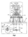
- Figure 1 illustrates the external appearance of a labeling apparatus constructed in accordance with the preferred embodiment of the invention.
- the labeling apparatus includes a sheet metal cabinet formed by a plurality of removable covers 10, 12, 14, 16.
- the control panel 18 contains a plurality of operator controls for controlling the operation of the apparatus.
- the disclosed labeling apparatus is adapted to apply tubular, flexible labels to either empty or filled containers such as "2-liter" soft drink bottles.
- the bottles 20 are brought to the machine on one of two conveyors, indicated by the reference characters 22a, 22b.
- a conveyor arrangement including one of the conveyors 22a, 22b brings the bottles 20 to a bottle presenting position indicated generally by the reference character 24.
- a bottle advancing mechanism indicated generally by the reference character 26 is operative to engage a bottle located at the label presenting position 24 and move it into a label applying position indicated generally by the reference character 28.
- the bottle is advanced out of the labeling position 28 by the product advancing mechanism 26 and onto an exit conveyor assembly 29 that carries the labeled bottles from the exit of the labeling apparatus.
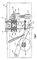
- a base or lower portion 30 of the apparatus supports and mounts a drive system constructed in accordance with the preferred embodiment of the invention.
- An upper portion 32 defines the labeling station indicated generally by the reference character 33.
- the upper portion 32 includes a supply of labels (not shown) preferably comprising a continuous tubular web 34 wound on a supply spindle (not shown), each individual label being defined by a pair of longitudinally spaced, transverse perforations 34a.
- the web of the labels is fed over a mandrel 40 (shown only in Figures 3 and 5) and then pulled over a product container 20a (shown in Figure 2) positioned below the mandrel 40.
- a product container 20a shown in Figure 2
- the label being applied is severed from the web 34 along the line of weakness 34a.
- the labeling station 33 is preferably similar in construction to the label assembly shown in U.S. Patent No. 4,620,888.
- the labeling station 33 includes a label position detector 42 and web braking devices 44.
- the detector 42 and other associated parts are omitted from Figure 5 in order to illustrate the details of the mandrel 40 and other related components.
- the web braking device 44 comprises a solenoid operated plunger 44a (shown in Figure 5) which when actuated clamps the web against the stationary mandrel 40 so that as the endmost label is pulled downwardly by a label applying assembly 46, the endmost label is severed from the remainder of the web along the label defining perforations 34a.
- the detector 42 is adjustably supported relative to the labeling station by a support assembly 48.
- the support assembly 48 includes slots 48a and link arm 48b by which the assembly is connected to the frame of the machine and which enables the support assembly to be adjustably positioned vertically and laterally as desired.
- the label applying assembly 46 is reciprocally movable in a vertical plane by carriage 50 operatively connected to the drive system located in the base 30 of the apparatus.
- the carriage 50 includes a pair of slide rods 52a, 52b that are slidably supported by upper and lower slide bearings 54, 55.
- Left and right hand halves 46a, 46b of the labeling applying assembly 46 are adjustably clamped to the left and right slide rods 52a, 52b, respectively.
- bottles to be labeled are advanced into the labeling position by the product advancing mechanism 26.
- the bottle advancing and stabilizing apparatus includes a pair of reciprocally mounted paddle-like star wheels 70, 72.
- the product advancing mechanism also includes an infeed star wheel 76 and a cooperating guide 78. The star wheel 76 advances a container from an entry conveyor to a bottle presenting position at which the paddle-like star wheels 70, 72 can engage the bottle and move it to the label applying position 28.
- the infeed star wheel 76 and the guide 78 are adapted to receive containers from either a side conveyor 22a (see Figure 1) or an inline conveyor 22b.
- the guide 78 comprises a substantially semi-circle shaped curved member (shown in Figure 8A).
- a smaller curved guide 78′ replaces the guide 78 that has an arc of approximately 90 degrees (see Figure 8A).
- the guide (whether it be guide 78 or guide 78′) is pivotally mounted to the machine on a pivot shaft 86.
- the opposite end of the guide is releasably held by a detent mechanism indicated generally by the reference character 88.
- the detent mechanism includes a spring loaded lever 90 having a roller 92 biased towards engagement with a detent notch 94 defined on the guide 78 by a tension spring 95.
- Both guides include a plurality of vertically disposed rollers 98 rotatably supported between top and bottom frame plates 99a, 99b. The rollers 98 facilitate movement of the container as the star wheel 76 is rotated.
- the detent mechanism 88 provides a malfunction sensor. In the event of a product jam in the vicinity of the star wheel 76, the guide 78 is forced out of the detent engaged position. An electrical switch 79 monitors movement and/or the position of the lever 90 or the guide 78 (or 78′) and terminates operation of the apparatus when a change in position or movement is sensed.
- the labeling machine as more fully described in U.S. Patent No. 4,620,888, may include a brake mechanism 81 (see Figure 4) for arresting motion in the drive system virtually instantaneously upon sensing a malfunction.
- the detent mechanism including the spring loaded arm 90, the roller 92 and the spring 95 are mounted to a base member 91.
- the base member 91 When switching between guide members 78 and 78′, the base member 91 is moved laterally with respect to the pivot 86 in order to engage the appropriate guide arm.
- the change in position of the base member 91 is clearly shown in Figures 8A and 8B.
- a conventional mounting arrangement for the base member is provided in the machine (not shown).
- the star wheels are mounted at the upper ends of rotatable slide shafts 102, 104.
- the lower ends of the slide shafts are rotatably coupled to a tie bar 106 which maintains the spacial distance between the slide shafts 102, 104 while allowing rotation of the shafts.
- Each slide shaft 102 passes through an associated bearing/drive gear assembly 108, 110.
- each the shaft 102, 104 is splined to the inside of its associated assembly.
- the tie bar 106 is operatively connected to an arm 112 which includes a cam follower 113 that rides on a drive cam 114.
- the arm 112 is biases towards the cam 114 by a pressurized actuator or cylinder 115.
- the engagement between the cam 114 and cam follower 113 is monitored. If separation is sensed as would occur due to a jam, the drive system is deactivated.
- the tie bar 106 is coupled to the drive arm 112 by means of a slot/pin engagement.
- a pin 116 forming part of the tie bar 106 extends through a slot 118 formed at a distal end of the arm 112.
- the arm is pivoted at a pivot 120.
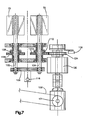
- the star wheels 70, 72 are intermittently rotated 90° by intermittent transmission 130.
- Such a transmission is available from Cyclo-Index Corporation and is sold under Model No. 2410-AV-90-1/4.
- the disclosed transmission 130 converts continuous rotary motion as conveyed to an input gear 131 by a chain 132 from the drive system, to intermit tent rotary motion in a output drive gear 134.
- the output gear 134 rotates 90 degrees and then dwells for 270 degrees.
- the drive gear 134 is connected to a gear operatively connected to the hub assembly 110 of the star wheel 72 which includes a gear 110a.
- the gear 110a is coupled to a gear 108a forming part of the hub assembly 108 of the star wheel 70 by means of a pair of idler gears 111a, 111b (shown in Figure 4). This interconnection produces synchronized, concurrent rotation in the star wheels 70, 72 when the output gear 134 rotates.
- the star wheels 70, 72 are shown in a lowered position which they assume near the end of the label applying cycle.
- the star wheels 70, 72 move downwardly to provide clearance for the gripper assemblies 46a, 46b (see Figure 3).
- the drive cam 114 for controlling movement in the star wheels 70, 72 is configured such that movement in the star wheels toward the lower position shown in Figure 6, does not begin until the label applying assembly 46 initially contacts the container located at the label applying position 28.
- the drive gear 134 includes a clutch mechanism which automatically declutches or decouples the transmission 130 from the star wheels should excessive torque be encountered.
- the clutch mechanism includes a sensor switch 136 (shown in Figure 6) for terminating or arresting motion in the drive system if excessive torque is encountered.
- a brake mechanism as described above may also be activated to arrest motion in the drive system virtually instantaneously.
- the infeed star wheel 76 is codriven with the star wheels 70, 72 but does not reciprocate vertically since it is located out of a path of movement of the label gripping assemblies 46.
- an idler gear 140 couples the star wheel 72 to a gear 142 forming part of or attached to, the star wheel 76.
- the cams and drive system are synchronized so that the label applying assembly and star wheels are vertically reciprocated in a synchronized relationship.
- the intermittent transmission is synchronized so that the star wheels 70, 72 and infeed star wheel 76 are intermittently rotated to advance a container from a product presenting position into the label applying position when the label applying assembly 46 is in the raised position.
- the drive motor 202 continuously drives the main drive shaft 200 to which the cams 58, 114 are mounted and which drives the intermittent transmission via the chain 132.
- continuous actuation of the drive motor 200 produces reciprocating, synchronized motion in the label applying assembly 46 and star wheels 70, 72 while at the same time producing intermittent rotation of the infeed star wheel and paired star wheels 70, 72 to effect advancement of a bottle or other product from an input conveyor to the label applying position 28 defined at the labeling station.
- the exit conveyor is power driven by a motor including a gearbox 150 through a chain 152.
- the exit conveyor assembly includes a continuous chain of rollers 154 having an upper run 154a and a lower run 154b.
- the chain of rollers comprises a pair of spaced apart, side-by-side chains 156, 158 reeved around associated sprockets 160, 162.
- the sprockets 160 are attached to a common shaft 164 which is driven by the chain 152 by means of an outboard sprocket (not shown).
- the other sprockets 162 constitute idler sprockets and our rotatably coupled to, or supported by an idler shaft 166.
- the chain of rollers includes a plurality of individual rollers 155 that are each rotatably supported on an associated shaft 155a.
- Each shaft 155a spans the chains 156, 158 and is held between individual chain links of the chains.
- the chain links include hollow pins which are adapted to receive ends 157 of the shaft 155a.
- the shafts 155a are held in position by retainers 168 mounted at the opposite ends 157 of the shaft 155a.
- the upper and lower runs 154a, 154b of the chains are supported by guide blocks 170, 172, respectively. The guide blocks slidably support the chains while maintaining their alignment.
- the shafts 164, 166 that support the sprockets 160, 162, respectively are rotatably supported by side plates 174, 176 forming part of the exit conveyor assembly.
- a base plate 178 interconnects the side plates 174, 176.
- Suitable fasteners 180 secure the assembly together.
- containers exiting the labeling station are allowed to move at a rate greater than the velocity of the conveyor.
- the conveyor is preferably continuously moving to transport labeled products from the product labeling machine to another location.
- a labeled container that is pushed out of the labeling station normally moves at a much more rapid rate than the conveyor velocity.
- the rolls 155 allow the container to easily move onto the conveyor (under the action of the star wheels 70, 72) even though the conveyor itself is moving at a slower linear speed. With the disclosed conveyor, transport of the label products from the machine are facilitated.
Landscapes
- Labeling Devices (AREA)
Applications Claiming Priority (2)
| Application Number | Priority Date | Filing Date | Title |
|---|---|---|---|
| US07/264,443 US4944825A (en) | 1988-10-28 | 1988-10-28 | Labeling apparatus |
| US264443 | 2008-11-04 |
Publications (1)
| Publication Number | Publication Date |
|---|---|
| EP0367401A1 true EP0367401A1 (en) | 1990-05-09 |
Family
ID=23006095
Family Applications (1)
| Application Number | Title | Priority Date | Filing Date |
|---|---|---|---|
| EP89309743A Withdrawn EP0367401A1 (en) | 1988-10-28 | 1989-09-25 | Labeling apparatus |
Country Status (4)
| Country | Link |
|---|---|
| US (1) | US4944825A (pt) |
| EP (1) | EP0367401A1 (pt) |
| CA (1) | CA1332161C (pt) |
| PT (1) | PT92143A (pt) |
Cited By (2)
| Publication number | Priority date | Publication date | Assignee | Title |
|---|---|---|---|---|
| CN103129788A (zh) * | 2011-12-05 | 2013-06-05 | 克朗斯股份公司 | 用于以弹性的标签套给容器贴标签的设备和方法 |
| CN107207112A (zh) * | 2015-01-29 | 2017-09-26 | 惠州市吉瑞科技有限公司 | 一种自动贴标机送料设备及采用该送料设备的送料方法 |
Families Citing this family (22)
| Publication number | Priority date | Publication date | Assignee | Title |
|---|---|---|---|---|
| US5232541A (en) * | 1991-05-31 | 1993-08-03 | Automated Packaging Systems, Inc. | Apparatus for registering bottles |
| DE69318233D1 (de) * | 1992-07-21 | 1998-06-04 | Venture Packaging Inc | Vorrichtung zum Aufbringen von hülsenförmigen Etiketten auf eine Vielzahl von Flaschen oder sonstigen Behältern |
| ZA954080B (en) * | 1994-05-23 | 1996-08-12 | Automated Label Syst Co | Method and apparatus for registering bottles |
| FR2783235B1 (fr) * | 1998-09-14 | 2000-11-10 | Prot Decoration Conditionnemen | Machine pour la pose de manchons d'etiquetage sur des bouteilles |
| US6263940B1 (en) | 1999-04-21 | 2001-07-24 | Axon Corporation | In-line continuous feed sleeve labeling machine and method |
| US6550226B1 (en) | 1999-10-27 | 2003-04-22 | Gates Automation, Inc. | Bag filling and sealing machine and method for handling bags |
| US6742321B2 (en) | 2002-09-30 | 2004-06-01 | Gates Automation, Inc. | Flange alignment and grasping assembly for bag handling apparatus |
| US7536767B2 (en) | 2005-05-27 | 2009-05-26 | Prairie Packaging, Inc. | Method of manufacturing a reinforced plastic foam cup |
| US7814647B2 (en) | 2005-05-27 | 2010-10-19 | Prairie Packaging, Inc. | Reinforced plastic foam cup, method of and apparatus for manufacturing same |
| US7694843B2 (en) | 2005-05-27 | 2010-04-13 | Prairie Packaging, Inc. | Reinforced plastic foam cup, method of and apparatus for manufacturing same |
| US7818866B2 (en) | 2005-05-27 | 2010-10-26 | Prairie Packaging, Inc. | Method of reinforcing a plastic foam cup |
| US7704347B2 (en) | 2005-05-27 | 2010-04-27 | Prairie Packaging, Inc. | Reinforced plastic foam cup, method of and apparatus for manufacturing same |
| US7552841B2 (en) | 2005-05-27 | 2009-06-30 | Prairie Packaging, Inc. | Reinforced plastic foam cup, method of and apparatus for manufacturing same |
| US7850003B2 (en) | 2006-03-17 | 2010-12-14 | Illinois Tool Works Inc. | Heat-shrinkable holder for articles, heat-shrinkable package of articles, and method of packaging articles |
| US7832553B2 (en) * | 2006-03-17 | 2010-11-16 | Illinois Tool Works Inc. | Heat-shrinkable holder for articles, heat-shrinkable package of articles, heat-shrinkable sleeve for articles, and method and device for packaging and sleeving articles |
| US7861490B2 (en) * | 2006-03-17 | 2011-01-04 | Illinois Tool Works Inc. | Method of packaging articles |
| US9623622B2 (en) * | 2010-02-24 | 2017-04-18 | Michael Baines | Packaging materials and methods |
| US8828170B2 (en) | 2010-03-04 | 2014-09-09 | Pactiv LLC | Apparatus and method for manufacturing reinforced containers |
| NL2010994C2 (en) * | 2013-06-17 | 2014-12-18 | Fuji Seal Europe Bv | Container sleeving method and device. |
| US9944422B2 (en) | 2014-04-04 | 2018-04-17 | Brady Worldwide, Inc. | Sleeve applicator machine and related method of operation |
| US10569399B1 (en) | 2017-11-03 | 2020-02-25 | Brady Worldwide, Inc. | Wire sleeve hand application tool |
| CN108946067A (zh) * | 2018-07-23 | 2018-12-07 | 东莞理工学院 | 一种弯头组装与贴标装置 |
Citations (4)
| Publication number | Priority date | Publication date | Assignee | Title |
|---|---|---|---|---|
| US2723743A (en) * | 1951-05-16 | 1955-11-15 | Meyer Geo J Mfg Co | Labeling machine having means for orienting an article through a predetermined angle |
| US2985283A (en) * | 1954-04-13 | 1961-05-23 | Meyer Geo J Mfg Co | Motor control means for spotting mechanism |
| US4102728A (en) * | 1977-05-19 | 1978-07-25 | Sterling Associates, Inc. | Label applying apparatus |
| US4412876A (en) * | 1981-07-07 | 1983-11-01 | Automated Packaging Systems, Inc. | Labeling apparatus |
Family Cites Families (9)
| Publication number | Priority date | Publication date | Assignee | Title |
|---|---|---|---|---|
| US2262799A (en) * | 1940-06-14 | 1941-11-18 | Pneumatic Seale Corp Ltd | Container feeding device |
| US2914894A (en) * | 1956-03-26 | 1959-12-01 | Hansen Oscar Anton | Process and apparatus for separating the foremost one of a stack of nested cup-shaped caps from the remainder of the stack and conveying it to a position at a distance from the stack |
| US2987313A (en) * | 1957-05-28 | 1961-06-06 | Owens Illinois Glass Co | Bottle holder |
| US4108705A (en) * | 1977-04-07 | 1978-08-22 | Owens-Illinois, Inc. | Bottle operated label feed switch mechanism |
| DE3143511A1 (de) * | 1981-11-03 | 1983-05-11 | Pirzer, Carl, 8402 Neutraubling | Ein- und auslaufstern |
| US4473429A (en) * | 1982-09-28 | 1984-09-25 | Label-Aire Inc. | High speed wrap around label applicator and method |
| US4565592A (en) * | 1984-07-02 | 1986-01-21 | Automated Packaging Systems, Inc. | Automated manufacturing monitoring |
| US4620888A (en) * | 1984-09-04 | 1986-11-04 | Automated Packaging Systems, Inc. | Labeling apparatus |
| DE3504555A1 (de) * | 1985-02-11 | 1986-10-30 | Jagenberg AG, 4000 Düsseldorf | Vorrichtung zum verteilen von gegenstaenden, insbesondere flaschen |
-
1988
- 1988-10-28 US US07/264,443 patent/US4944825A/en not_active Expired - Fee Related
-
1989
- 1989-09-18 CA CA000611793A patent/CA1332161C/en not_active Expired - Fee Related
- 1989-09-25 EP EP89309743A patent/EP0367401A1/en not_active Withdrawn
- 1989-10-27 PT PT92143A patent/PT92143A/pt unknown
Patent Citations (4)
| Publication number | Priority date | Publication date | Assignee | Title |
|---|---|---|---|---|
| US2723743A (en) * | 1951-05-16 | 1955-11-15 | Meyer Geo J Mfg Co | Labeling machine having means for orienting an article through a predetermined angle |
| US2985283A (en) * | 1954-04-13 | 1961-05-23 | Meyer Geo J Mfg Co | Motor control means for spotting mechanism |
| US4102728A (en) * | 1977-05-19 | 1978-07-25 | Sterling Associates, Inc. | Label applying apparatus |
| US4412876A (en) * | 1981-07-07 | 1983-11-01 | Automated Packaging Systems, Inc. | Labeling apparatus |
Cited By (3)
| Publication number | Priority date | Publication date | Assignee | Title |
|---|---|---|---|---|
| CN103129788A (zh) * | 2011-12-05 | 2013-06-05 | 克朗斯股份公司 | 用于以弹性的标签套给容器贴标签的设备和方法 |
| EP2602198A1 (de) * | 2011-12-05 | 2013-06-12 | Krones AG | Vorrichtung und Verfahren zum Etikettieren von Behältern mit elastischen Etikettenhülsen |
| CN107207112A (zh) * | 2015-01-29 | 2017-09-26 | 惠州市吉瑞科技有限公司 | 一种自动贴标机送料设备及采用该送料设备的送料方法 |
Also Published As
| Publication number | Publication date |
|---|---|
| CA1332161C (en) | 1994-09-27 |
| PT92143A (pt) | 1990-04-30 |
| US4944825A (en) | 1990-07-31 |
Similar Documents
| Publication | Publication Date | Title |
|---|---|---|
| US4944825A (en) | Labeling apparatus | |
| US4412876A (en) | Labeling apparatus | |
| US4544431A (en) | Roll fed labelling machine | |
| AU677018B2 (en) | Method and apparatus for decorating articles | |
| US3742677A (en) | Method and apparatus for applying a carrier to a cluster of containers | |
| EP0344932A1 (en) | Straight through labelling machine | |
| EP1113963B1 (en) | Process and apparatus to apply adhesive band on moving objects | |
| US5069016A (en) | Method and apparatus for continuously packaging batches of containers or the like | |
| GB2027410A (en) | Application of labels to articles | |
| US4283245A (en) | Bottle labelling apparatus | |
| US5477956A (en) | Vessel processing system and process | |
| EP1245491B1 (en) | Method and machine for forming a sealed air bag | |
| JPH0825529B2 (ja) | 物品包装装置および包装方法 | |
| GB2050322A (en) | High speed straight line container sealing machine | |
| US5820714A (en) | Method and apparatus for registering bottles | |
| US4068450A (en) | Container capping machine | |
| JPH0776330A (ja) | 採血管などの自動供給装置 | |
| CN216916612U (zh) | 一种卧式圆瓶贴标机 | |
| JPH03158318A (ja) | 物品受渡し装置 | |
| GB2336580A (en) | Labelling articles on a conveyor | |
| CA1333476C (en) | Sleeve label applicator with coordinated label position sensor and web retraction means | |
| US5536357A (en) | Bag gripping and transfer apparatus and method | |
| KR0139104Y1 (ko) | 음료용기에 대한 포장스트로우 부착장치 | |
| JPH0321421B2 (pt) | ||
| CN217599057U (zh) | 一种直线式不干胶贴标机 |
Legal Events
| Date | Code | Title | Description |
|---|---|---|---|
| PUAI | Public reference made under article 153(3) epc to a published international application that has entered the european phase |
Free format text: ORIGINAL CODE: 0009012 |
|
| AK | Designated contracting states |
Kind code of ref document: A1 Designated state(s): AT BE CH DE ES FR GB GR IT LI LU NL SE |
|
| STAA | Information on the status of an ep patent application or granted ep patent |
Free format text: STATUS: THE APPLICATION IS DEEMED TO BE WITHDRAWN |
|
| 18D | Application deemed to be withdrawn |
Effective date: 19901110 |