EP0367429B1 - Recreational vehicle door assembly - Google Patents
Recreational vehicle door assembly Download PDFInfo
- Publication number
- EP0367429B1 EP0367429B1 EP89310441A EP89310441A EP0367429B1 EP 0367429 B1 EP0367429 B1 EP 0367429B1 EP 89310441 A EP89310441 A EP 89310441A EP 89310441 A EP89310441 A EP 89310441A EP 0367429 B1 EP0367429 B1 EP 0367429B1
- Authority
- EP
- European Patent Office
- Prior art keywords
- door
- frame
- door member
- latch
- movement
- Prior art date
- Legal status (The legal status is an assumption and is not a legal conclusion. Google has not performed a legal analysis and makes no representation as to the accuracy of the status listed.)
- Expired - Lifetime
Links
Images



Classifications
-
- E—FIXED CONSTRUCTIONS
- E05—LOCKS; KEYS; WINDOW OR DOOR FITTINGS; SAFES
- E05D—HINGES OR SUSPENSION DEVICES FOR DOORS, WINDOWS OR WINGS
- E05D3/00—Hinges with pins
- E05D3/06—Hinges with pins with two or more pins
- E05D3/12—Hinges with pins with two or more pins with two parallel pins and one arm
-
- B—PERFORMING OPERATIONS; TRANSPORTING
- B60—VEHICLES IN GENERAL
- B60J—WINDOWS, WINDSCREENS, NON-FIXED ROOFS, DOORS, OR SIMILAR DEVICES FOR VEHICLES; REMOVABLE EXTERNAL PROTECTIVE COVERINGS SPECIALLY ADAPTED FOR VEHICLES
- B60J5/00—Doors
-
- B—PERFORMING OPERATIONS; TRANSPORTING
- B60—VEHICLES IN GENERAL
- B60J—WINDOWS, WINDSCREENS, NON-FIXED ROOFS, DOORS, OR SIMILAR DEVICES FOR VEHICLES; REMOVABLE EXTERNAL PROTECTIVE COVERINGS SPECIALLY ADAPTED FOR VEHICLES
- B60J5/00—Doors
- B60J5/04—Doors arranged at the vehicle sides
- B60J5/0486—Special type
- B60J5/049—Special type caravan door
-
- B—PERFORMING OPERATIONS; TRANSPORTING
- B60—VEHICLES IN GENERAL
- B60J—WINDOWS, WINDSCREENS, NON-FIXED ROOFS, DOORS, OR SIMILAR DEVICES FOR VEHICLES; REMOVABLE EXTERNAL PROTECTIVE COVERINGS SPECIALLY ADAPTED FOR VEHICLES
- B60J5/00—Doors
- B60J5/04—Doors arranged at the vehicle sides
- B60J5/0486—Special type
- B60J5/0491—Special type lid, e.g. for luggage compartment accessible at vehicle side
-
- E—FIXED CONSTRUCTIONS
- E05—LOCKS; KEYS; WINDOW OR DOOR FITTINGS; SAFES
- E05B—LOCKS; ACCESSORIES THEREFOR; HANDCUFFS
- E05B53/00—Operation or control of locks by mechanical transmissions, e.g. from a distance
-
- E—FIXED CONSTRUCTIONS
- E05—LOCKS; KEYS; WINDOW OR DOOR FITTINGS; SAFES
- E05B—LOCKS; ACCESSORIES THEREFOR; HANDCUFFS
- E05B77/00—Vehicle locks characterised by special functions or purposes
-
- E—FIXED CONSTRUCTIONS
- E05—LOCKS; KEYS; WINDOW OR DOOR FITTINGS; SAFES
- E05C—BOLTS OR FASTENING DEVICES FOR WINGS, SPECIALLY FOR DOORS OR WINDOWS
- E05C9/00—Arrangements of simultaneously actuated bolts or other securing devices at well-separated positions on the same wing
- E05C9/10—Actuating mechanisms for bars
- E05C9/16—Actuating mechanisms for bars with crank pins and connecting rods
-
- E—FIXED CONSTRUCTIONS
- E05—LOCKS; KEYS; WINDOW OR DOOR FITTINGS; SAFES
- E05B—LOCKS; ACCESSORIES THEREFOR; HANDCUFFS
- E05B83/00—Vehicle locks specially adapted for particular types of wing or vehicle
- E05B83/36—Locks for passenger or like doors
- E05B83/44—Locks for passenger or like doors for recreational vehicles, e.g. caravans or camper vans
-
- E—FIXED CONSTRUCTIONS
- E05—LOCKS; KEYS; WINDOW OR DOOR FITTINGS; SAFES
- E05C—BOLTS OR FASTENING DEVICES FOR WINGS, SPECIALLY FOR DOORS OR WINDOWS
- E05C9/00—Arrangements of simultaneously actuated bolts or other securing devices at well-separated positions on the same wing
- E05C9/06—Arrangements of simultaneously actuated bolts or other securing devices at well-separated positions on the same wing with three or more sliding bars
-
- E—FIXED CONSTRUCTIONS
- E05—LOCKS; KEYS; WINDOW OR DOOR FITTINGS; SAFES
- E05D—HINGES OR SUSPENSION DEVICES FOR DOORS, WINDOWS OR WINGS
- E05D11/00—Additional features or accessories of hinges
- E05D11/10—Devices for preventing movement between relatively-movable hinge parts
- E05D11/1007—Devices for preventing movement between relatively-movable hinge parts with positive locking
-
- E—FIXED CONSTRUCTIONS
- E05—LOCKS; KEYS; WINDOW OR DOOR FITTINGS; SAFES
- E05Y—INDEXING SCHEME ASSOCIATED WITH SUBCLASSES E05D AND E05F, RELATING TO CONSTRUCTION ELEMENTS, ELECTRIC CONTROL, POWER SUPPLY, POWER SIGNAL OR TRANSMISSION, USER INTERFACES, MOUNTING OR COUPLING, DETAILS, ACCESSORIES, AUXILIARY OPERATIONS NOT OTHERWISE PROVIDED FOR, APPLICATION THEREOF
- E05Y2900/00—Application of doors, windows, wings or fittings thereof
- E05Y2900/50—Application of doors, windows, wings or fittings thereof for vehicles
- E05Y2900/512—Application of doors, windows, wings or fittings thereof for vehicles for recreational vehicles
-
- E—FIXED CONSTRUCTIONS
- E05—LOCKS; KEYS; WINDOW OR DOOR FITTINGS; SAFES
- E05Y—INDEXING SCHEME ASSOCIATED WITH SUBCLASSES E05D AND E05F, RELATING TO CONSTRUCTION ELEMENTS, ELECTRIC CONTROL, POWER SUPPLY, POWER SIGNAL OR TRANSMISSION, USER INTERFACES, MOUNTING OR COUPLING, DETAILS, ACCESSORIES, AUXILIARY OPERATIONS NOT OTHERWISE PROVIDED FOR, APPLICATION THEREOF
- E05Y2900/00—Application of doors, windows, wings or fittings thereof
- E05Y2900/50—Application of doors, windows, wings or fittings thereof for vehicles
- E05Y2900/53—Type of wing
-
- Y—GENERAL TAGGING OF NEW TECHNOLOGICAL DEVELOPMENTS; GENERAL TAGGING OF CROSS-SECTIONAL TECHNOLOGIES SPANNING OVER SEVERAL SECTIONS OF THE IPC; TECHNICAL SUBJECTS COVERED BY FORMER USPC CROSS-REFERENCE ART COLLECTIONS [XRACs] AND DIGESTS
- Y10—TECHNICAL SUBJECTS COVERED BY FORMER USPC
- Y10S—TECHNICAL SUBJECTS COVERED BY FORMER USPC CROSS-REFERENCE ART COLLECTIONS [XRACs] AND DIGESTS
- Y10S292/00—Closure fasteners
- Y10S292/43—Rear deck lid latches
-
- Y—GENERAL TAGGING OF NEW TECHNOLOGICAL DEVELOPMENTS; GENERAL TAGGING OF CROSS-SECTIONAL TECHNOLOGIES SPANNING OVER SEVERAL SECTIONS OF THE IPC; TECHNICAL SUBJECTS COVERED BY FORMER USPC CROSS-REFERENCE ART COLLECTIONS [XRACs] AND DIGESTS
- Y10—TECHNICAL SUBJECTS COVERED BY FORMER USPC
- Y10T—TECHNICAL SUBJECTS COVERED BY FORMER US CLASSIFICATION
- Y10T292/00—Closure fasteners
- Y10T292/08—Bolts
- Y10T292/0801—Multiple
- Y10T292/0834—Sliding
- Y10T292/0836—Operating means
- Y10T292/0838—Lever and push or pull rod
-
- Y—GENERAL TAGGING OF NEW TECHNOLOGICAL DEVELOPMENTS; GENERAL TAGGING OF CROSS-SECTIONAL TECHNOLOGIES SPANNING OVER SEVERAL SECTIONS OF THE IPC; TECHNICAL SUBJECTS COVERED BY FORMER USPC CROSS-REFERENCE ART COLLECTIONS [XRACs] AND DIGESTS
- Y10—TECHNICAL SUBJECTS COVERED BY FORMER USPC
- Y10T—TECHNICAL SUBJECTS COVERED BY FORMER US CLASSIFICATION
- Y10T292/00—Closure fasteners
- Y10T292/175—Bolt releasers
- Y10T292/18—Free-end-engaging means
Definitions
- This invention relates generally to hinged doors for closing off and providing access to compartments and more particularly to an improved door assembly for a compartment in a recreational vehicle which is to be accessed from outside the vehicle.
- US-A-4 372 603 discloses a door assembly providing the basis for the prior art portion of claim 1.
- This prior door assembly is swingable about a vertical axis with a seal member being squeezed between the door and the door frame in its closed position.
- the resilient member is incapable of opening the door when the door in unlatched since the latching mechanism is a lever-operated mechanism which needs to laterally displace the door from a retaining flange before it can be swung open.
- the present invention is required to provide an easily openable door for a recreational vehicle which, when the door is appropriately mounted to the vehicle, can be swung about a horizontal axis without the need for a protruding latching mechanism in order to retain the aesthetic appearance of the recreational vehicle.
- a door assembly for a compartment in a vehicle which is to be accessed from outside the vehicle, said door assembly comprising a generally upright rectangular frame defining an access opening, a rectangular door member having an outer side and an inner side and being of a size to fit in said opening, hinge means mounting said door member on said frame for movement between an open position and a closed position fitting in said opening, substantially continuous seal means extending around said opening at a position between said door member and said frame in said closed position of said door member, said seal means being formed of a yieldable material and being compressed between said door member and said frame in said closed position of said door member, and means to maintain said door member in said closed position, characterised in that the door assembly is for use in a recreational vehicle with the door member being mounted for up and down swinging movement to and from the open position in which it is disposed above said opening, in that the means to maintain the door member in its closed position comprises latch means carried by said door member and engageable with said frame, and in that a latch release member is movably mounted on
- the latch structure on the inside of the door engages the frame to maintain the door in a closed position.
- the seal expands and moves the door outwardly at its bottom end so that it can readily be grasped and moved upwardly to its open position.
- a latch release member is movably mounted on the frame at a position above the door member and is operable to release the latch structure to enable the compressed seal to expand and urge the door member at its lower end to its open position.
- a separate lock member is associated with the latch release member so that, when desired, the door can be locked in its closed, latched position.
- the latch release member and the lock member are conveniently arranged side-by-side on the frame at a position above the door where they can readily be used by a person desiring access to the compartment.
- hinge members are provided for hingedly mounting the upper end of the door on the frame. These hinge members enable the door to be moved to an open position located above the door frame and in a plane substantially parallel to the door frame.
- the hinge members can be embodied in the door assembly so that only small portions of the hinge members are visible from outside the recreational vehicle to thereby avoid the undesirable result of having the door assembly detract from the overall appearance of the recreational vehicle.
- a unique latch operating mechanism is mounted on the inside of the door so that the door and frame assembly can be supplied as a unit to RV manufacturers.
- the overall result is an improved door assembly which provides desired results and also provides a clean appearance which does not detract from the overall appearance of the recreational vehicle in which it is installed.
- a pair of door assemblies of this invention are illustrated in Fig. 1 mounted in a side wall 12 of a recreational vehicle 14 which can either be a motor home or a travel trailer.
- the doors 10 provide access from outside the vehicle 14 to compartments which can be used for storage of cargo, luggage or the like or other similar purposes.
- a recreational vehicle (RV) in common use today can have as many as ten such doors 10 or can have a fewer number.
- the door assemblies 10 provide access to internal compartments and perform a useful and necessary function in the day-to-day use of the RV 14.
- a door assembly 10 consists principally of an upright rectangular frame 16 provided with a rectangular access opening 18 having an upper end 20 and a lower end 22.
- the door assembly 10 also includes a rectangular door 24 having an outer side 26 and an inner side 28 (Fig. 2) and of a size to fit in the rectangular opening 18.
- the door 24 is mounted on hinges 32 carried by the frame 16 so that the door 24 can be moved from its closed position shown in Fig. 1 to an upwardly extending open position illustrated in broken lines in Fig. 8.
- the frame 16 at a position above the door 24, is provided with a recess 34 in which a latch release member 36 is mounted in a side-by-side relation with a conventional lock member 38 operable by a key 40.
- the door 34 can be released from a latched closed position by merely actuating the latch release member 36 and the door 24 can be locked in a closed position or unlocked by merely actuating the lock member 38 with the key 40.
- the members 36 and 38 are conveniently located at a position above the door 24 and the embodiment of the latching and locking functions in the separate members 36 and 38 makes it unnecessary to continually use the key 40 in order to obtain access to the compartment behind the door 24.
- a seal member 42 extends continuously around the border of the door member 24 on the inside 28 of the door.
- the seal member 42 is hollow and is formed of a resilient material with a retaining leg 44 being retained in a retaining slot 46 formed in the door 24 adjacent its peripheral edge 48 (Fig. 6).
- the frame 16 is formed with a continuous inwardly extending flange 50 which, in the closed position of the door 24, is positioned to engage the seal member 42.
- the flange 50 is inclined, particularly at the top of the door 24 so that the seal 42 will abut the flange 50 rather than slide over the flange 50 as the door 24 is being closed.
- the engagement of the seal member 42 with the flange 50 provides for a weather tight and water tight engagement of the door 24 with the frame 16 when the door 24 is in its closed position. This insures the security of the contents of the compartment which is closed by the door 24.
- the latch members 54 are released by the application of manual thumb pressure on an actuating button portion 59 of the latch release member 36. Such pressure is operable to move a tubular body portion 60 of the member 36 inwardly of the door frame 16 to in turn rotate a bell crank member 62 in a clockwise direction (Fig. 4) about its supporting pivot 64.
- the bell crank member 62 has one leg 66 which is engaged with the member 36 and a second leg 68 which engages a downwardly extending actuator rod 70.
- the rod 70 projects into the door opening 20 where it is engagable with the upper end 72 (Fig. 2) of an upright post member 74 slidably mounted in bearing members 76 mounted on the inner side 28 of the door member 24.
- the post member 74 forms part of a latch operating mechanism 75 mounted on the inner side 28 of the door 24. At its lower end 78, the post member 74 is pivotally connected to a rotary force transmitting member 80 which is secured at diametrically opposite points to tension members 82 which extend in opposite directions from the member 80. At their opposite ends, the tension members 82 are pivotally connected to rotary members 84 that are rotatably mounted on the inner side 28 of the door 24.
- the rotary members 84 are also pivotally connected to downwardly extending actuators 86 (Fig. 6) which are in turn connected by pins 88 to spring pressed slide shafts 90 on which the latch members 54 are mounted.
- the bell crank member 62 is actuated to move the member 70 downwardly to in turn push the post 74 downwardly to rotate the force transmitting member 80 in a clockwise direction to place the tension members 82 in tension to in turn rotate the members 84 in a direction to lift the latch members 54 into release positions in which they are in a clearance relation with the flange 50 at the lower end 22 of the opening 20.
- a compression spring 92 on the door frame 16 applies a force to the latch release member 36 that is effective to move the member 36 back to its set position illustrated in Fig. 4 in which a stop 94 on the member 36 engages a stop 98 on the frame 16.
- the spring 92 maintains the 36 in its set position until it is again manually moved by thumb pressure as described above.
- each of the latch members 54 is provided with an inclined cam face so that when the door 24 is closed, the cam face 100 will engage the flange 50 at the lower end of the door opening 20 and the latch member 54 will be urged upwardly to a position in which it will clear the flange 50 and a spring 102 will urge the latch member 100 to its latching position behind the flange 50, as shown in Fig. 6.
- the lock member 38 is secured to the frame 16 by a conventional nut assembly so that the lock member body 106 is rotatable to a position in which a blocking member or bar 108 on the body 106 is adjacent the inner end of the latch release body portion 60 so as to block inward movement of the body portion 60 to actuate the bell crank 62. In this position of the blocking member 108, the door 24 is locked in a closed latched position.
- the key 40 is operable in the lock member 38 to rotate the body 106 to a position in which the blocking member 108 is in a clearance relation with the latch release member 36 so that the member 36 can be moved inwardly to actuate the latch operating mechanism 75 to lift the latch members 54.
- each of the hinge members 32 consists of an upright stem portion 110 which is long and narrow in a vertical direction so as to be relatively unobtrusive from an appearance standpoint when viewing the assembly 10 from outside the vehicle 14.
- Each hinge member 32 also includes a pair of oppositely extending shaft portions 112 at the upper and lower ends of the stem portion 110.
- the shaft portions 112 are located inwardly of the outer surface 114 of the stem portion 110 so that the shaft portions 112 are positioned rearwardly of the outer surface 26 of the door 24.
- each hinge member 32 is such that the stem portion 110 fits in a rectangular slot 118 in the door 24 so that the surface 114 of the stem portion 110 is flush with the surface 26 of the door 24.
- the shaft portions 112 are located rearwardly of the door surface 26 and are received in a receptacle 120 formed on the inner side 28, of the door 24.
- the receptacle 120 has a plurality of generally U-shape journal portions 122 in which the shaft portions 112 are rotatably supported.
- Cover members 124 have downwardly extending retainer portions 126 which engage the top sides of the shaft portions 112 so as to maintain them in bearing contact with the journal portions 122.
- Retainer screws 128 are provided for extending through openings 130 in the cover members 124 and into threaded openings 132 in the receptacle 120 for retaining the shaft portions 112 journalled in the receptacles 120.
- the lowermost shaft portions 112 on the hinges 32 are journalled on the door 24 adjacent the upper end thereof.
- the upper shaft portions are similarly journalled in receptacles 134 formed on the frame 16.
- Fig. 8 wherein it is seen that the door 24 is movable about the upper shaft portions 112 to a substantially horizontal position, shown in broken lines, and subsequently about the lower shaft portions 112 to an upright position disposed above the opening 18 in a substantially parallel relation with the frame 16.
- the door 24 is readily released from a latched position by thumb pressure on the latch release member 36 and is then readily grasped at the lower end of the door 24 and moved upwardly to a horizontal position or further upwardly to a vertical position in which full access to the compartment behind the door 24 is provided.
- the location of the latch release member 36 at a position above the door 24 provides for a convenient location for opening the door 24 to one standing beside the RV 14.
- use of the key 40 is not required at all times in order to place the door 24 in a closed latched position or to open the door 24.
- the locking member 38 is always available in the event locking of the door 24 is desired.
- the compartment behind the door 24 is constantly maintained in a weather tight condition so as to protect the contents.
Landscapes
- Engineering & Computer Science (AREA)
- Mechanical Engineering (AREA)
- Lock And Its Accessories (AREA)
- Specific Sealing Or Ventilating Devices For Doors And Windows (AREA)
- Body Structure For Vehicles (AREA)
Description
- This invention relates generally to hinged doors for closing off and providing access to compartments and more particularly to an improved door assembly for a compartment in a recreational vehicle which is to be accessed from outside the vehicle.
- Conventional doors for external compartments in recreational vehicles have been very rudimentary in nature, difficult to open and close, not at all weathertight, and somewhat unsightly. As a result, articles stored in RV compartments, such as luggage and cargo, are subject to weather damage, are likely to become soiled during transit and are subject to theft and vandalism.
- Furthermore, conventional doors are often unattractive and tend to detract from the overall appearance of the RV.
- It is the principal object of the present invention, therefore, to provide an improved door assembly for an outside compartment in a recreational vehicle which is weathertight, is easy to open and close, has separate latching and locking functions conveniently located to compartment users and does not detract from the appearance of the recreational vehicle.
- US-A-4 372 603 discloses a door assembly providing the basis for the prior art portion of claim 1. This prior door assembly is swingable about a vertical axis with a seal member being squeezed between the door and the door frame in its closed position. However, the resilient member is incapable of opening the door when the door in unlatched since the latching mechanism is a lever-operated mechanism which needs to laterally displace the door from a retaining flange before it can be swung open.
- The present invention is required to provide an easily openable door for a recreational vehicle which, when the door is appropriately mounted to the vehicle, can be swung about a horizontal axis without the need for a protruding latching mechanism in order to retain the aesthetic appearance of the recreational vehicle.
- According to the present invention there is provided a door assembly for a compartment in a vehicle which is to be accessed from outside the vehicle, said door assembly comprising a generally upright rectangular frame defining an access opening, a rectangular door member having an outer side and an inner side and being of a size to fit in said opening, hinge means mounting said door member on said frame for movement between an open position and a closed position fitting in said opening, substantially continuous seal means extending around said opening at a position between said door member and said frame in said closed position of said door member, said seal means being formed of a yieldable material and being compressed between said door member and said frame in said closed position of said door member, and means to maintain said door member in said closed position, characterised in that the door assembly is for use in a recreational vehicle with the door member being mounted for up and down swinging movement to and from the open position in which it is disposed above said opening, in that the means to maintain the door member in its closed position comprises latch means carried by said door member and engageable with said frame, and in that a latch release member is movably mounted on said frame and is operable to release said latch means to enable said compressed seal means to expand and urge said door member toward an open position, wherein when the door member is mounted for up and down swinging movement to and from an open position in which it is disposed above the opening the compressed seal means is arranged to urge the door member towards the open position at the lower end of said opening.
- When the door member is mounted to the vehicle for up and down swinging movement to and from an open position above the opening, upon operation of the latch release member the door member will be urged to an initially open position by the seal means whereby it can then be swung open from the bottom edge.
- In the illustrated embodiment the latch structure on the inside of the door engages the frame to maintain the door in a closed position. When the latch is released, the seal expands and moves the door outwardly at its bottom end so that it can readily be grasped and moved upwardly to its open position. A latch release member is movably mounted on the frame at a position above the door member and is operable to release the latch structure to enable the compressed seal to expand and urge the door member at its lower end to its open position. A separate lock member is associated with the latch release member so that, when desired, the door can be locked in its closed, latched position. The embodying of the latching and locking features in separate structures enables the door to be opened and closed at will, without the necessity for a key but also enables the locking of the door in its closed position for security purposes.
- In the illustrated embodiment the latch release member and the lock member are conveniently arranged side-by-side on the frame at a position above the door where they can readily be used by a person desiring access to the compartment.
- Special hinge members are provided for hingedly mounting the upper end of the door on the frame. These hinge members enable the door to be moved to an open position located above the door frame and in a plane substantially parallel to the door frame. In addition, the hinge members can be embodied in the door assembly so that only small portions of the hinge members are visible from outside the recreational vehicle to thereby avoid the undesirable result of having the door assembly detract from the overall appearance of the recreational vehicle. Further, a unique latch operating mechanism is mounted on the inside of the door so that the door and frame assembly can be supplied as a unit to RV manufacturers.
- The overall result is an improved door assembly which provides desired results and also provides a clean appearance which does not detract from the overall appearance of the recreational vehicle in which it is installed.
- Further objects, features and advantages of the invention will become apparent from a consideration of the following description and the appended claims when taken in connection with the accompanying drawing in which:
- Fig. 1 is a fragmentary perspective view of a portion of an RV equipped with a pair of the door assemblies of this invention;
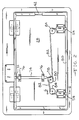
- Fig. 2 is an elevational view of the inward side of the door assembly of this invention;
- Fig. 3 is a fragmentary elevational view of the door latching and locking actuators in the door assembly of this invention as viewed from the inward side of the door;
- Fig. 4 is a fragmentary sectional view of the latch actuator as seen from substantially the line 4-4 in Fig. 3;
- Fig. 5 is a sectional view of the latching and locking actuators shown in Fig. 3 as viewed from substantially the line 5-5 in Fig. 3;
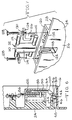
- Fig. 6 is an enlarged fragmentary sectional view of a portion of the latching mechanism in the door assembly of this invention as seen from substantially the line 6-6 in Fig. 2;
- Fig. 7 is a fragmentary exploded perspective view of a hinge assembly in the door assembly of this invention; and
- Fig. 8 is a vertical sectional view of the door assembly of this invention illustrating the door in both its open and closed positions.
- With reference to the drawing, a pair of door assemblies of this invention, indicated generally at 10, are illustrated in Fig. 1 mounted in a
side wall 12 of arecreational vehicle 14 which can either be a motor home or a travel trailer. Thedoors 10 provide access from outside thevehicle 14 to compartments which can be used for storage of cargo, luggage or the like or other similar purposes. A recreational vehicle (RV) in common use today can have as many as tensuch doors 10 or can have a fewer number. In any event, thedoor assemblies 10 provide access to internal compartments and perform a useful and necessary function in the day-to-day use of theRV 14. - A
door assembly 10 consists principally of an uprightrectangular frame 16 provided with a rectangular access opening 18 having anupper end 20 and alower end 22. Thedoor assembly 10 also includes arectangular door 24 having anouter side 26 and an inner side 28 (Fig. 2) and of a size to fit in therectangular opening 18. - At its
upper end 30, thedoor 24 is mounted onhinges 32 carried by theframe 16 so that thedoor 24 can be moved from its closed position shown in Fig. 1 to an upwardly extending open position illustrated in broken lines in Fig. 8. - The
frame 16, at a position above thedoor 24, is provided with arecess 34 in which a latch release member 36 is mounted in a side-by-side relation with aconventional lock member 38 operable by akey 40. As a result, thedoor 34 can be released from a latched closed position by merely actuating the latch release member 36 and thedoor 24 can be locked in a closed position or unlocked by merely actuating thelock member 38 with thekey 40. Themembers 36 and 38 are conveniently located at a position above thedoor 24 and the embodiment of the latching and locking functions in theseparate members 36 and 38 makes it unnecessary to continually use thekey 40 in order to obtain access to the compartment behind thedoor 24. - As shown in Fig. 2, a
seal member 42 extends continuously around the border of thedoor member 24 on theinside 28 of the door. Theseal member 42 is hollow and is formed of a resilient material with aretaining leg 44 being retained in aretaining slot 46 formed in thedoor 24 adjacent its peripheral edge 48 (Fig. 6). - As shown in Figs. 4 and 6, the
frame 16 is formed with a continuous inwardly extendingflange 50 which, in the closed position of thedoor 24, is positioned to engage theseal member 42. Theflange 50 is inclined, particularly at the top of thedoor 24 so that theseal 42 will abut theflange 50 rather than slide over theflange 50 as thedoor 24 is being closed. The engagement of theseal member 42 with theflange 50 provides for a weather tight and water tight engagement of thedoor 24 with theframe 16 when thedoor 24 is in its closed position. This insures the security of the contents of the compartment which is closed by thedoor 24. - As a result of the resilience of the
seal 42, when thedoor 24 is fully closed and latched in a closed position, theseal 42 is compressed, as shown in Figs. 4 and 6, so that theseal 42 exerts an outwardly directed force on thedoor 24 tending to open the door. Thedoor 24 is retained in its latched closed position by a pair of latch members 54 (Figs. 2 and 6) which are carried by the door and engage theinner side 56 of theflange 50 at thelower end 22 of the door opening 20 to maintain the door in a closed position. When thelatch members 54 are released from theflange 50, theseal member 42 will start to decompress and expand so as to push thedoor 24 toward an open position at thelower end 22 of the opening 20. As a result, the user desiring access to the compartment closed by thedoor 24 can readily grasp thelower edge 48 of the door and move the door from its closed position upwardly to its open position in Fig. 8. - The
latch members 54 are released by the application of manual thumb pressure on an actuating button portion 59 of the latch release member 36. Such pressure is operable to move atubular body portion 60 of the member 36 inwardly of thedoor frame 16 to in turn rotate abell crank member 62 in a clockwise direction (Fig. 4) about its supportingpivot 64. Thebell crank member 62 has oneleg 66 which is engaged with the member 36 and asecond leg 68 which engages a downwardly extendingactuator rod 70. Therod 70 projects into the door opening 20 where it is engagable with the upper end 72 (Fig. 2) of an upright post member 74 slidably mounted in bearingmembers 76 mounted on theinner side 28 of thedoor member 24. The post member 74 forms part of a latch operating mechanism 75 mounted on theinner side 28 of thedoor 24. At itslower end 78, the post member 74 is pivotally connected to a rotaryforce transmitting member 80 which is secured at diametrically opposite points totension members 82 which extend in opposite directions from themember 80. At their opposite ends, thetension members 82 are pivotally connected torotary members 84 that are rotatably mounted on theinner side 28 of thedoor 24. - The
rotary members 84 are also pivotally connected to downwardly extending actuators 86 (Fig. 6) which are in turn connected bypins 88 to spring pressedslide shafts 90 on which thelatch members 54 are mounted. As a result, when the latch release member 36 is pushed inwardly by thumb pressure on the outer button portion 59, thebell crank member 62 is actuated to move themember 70 downwardly to in turn push the post 74 downwardly to rotate theforce transmitting member 80 in a clockwise direction to place thetension members 82 in tension to in turn rotate themembers 84 in a direction to lift thelatch members 54 into release positions in which they are in a clearance relation with theflange 50 at thelower end 22 of the opening 20. - As soon as thumb pressure on the latch release member 36 is released, a
compression spring 92 on thedoor frame 16 applies a force to the latch release member 36 that is effective to move the member 36 back to its set position illustrated in Fig. 4 in which astop 94 on the member 36 engages astop 98 on theframe 16. Thespring 92 maintains the 36 in its set position until it is again manually moved by thumb pressure as described above. - As shown in Fig. 6, the
inner side 100 of each of thelatch members 54 is provided with an inclined cam face so that when thedoor 24 is closed, thecam face 100 will engage theflange 50 at the lower end of the door opening 20 and thelatch member 54 will be urged upwardly to a position in which it will clear theflange 50 and aspring 102 will urge thelatch member 100 to its latching position behind theflange 50, as shown in Fig. 6. - The
lock member 38 is secured to theframe 16 by a conventional nut assembly so that thelock member body 106 is rotatable to a position in which a blocking member orbar 108 on thebody 106 is adjacent the inner end of the latchrelease body portion 60 so as to block inward movement of thebody portion 60 to actuate thebell crank 62. In this position of the blockingmember 108, thedoor 24 is locked in a closed latched position. The key 40 is operable in thelock member 38 to rotate thebody 106 to a position in which the blockingmember 108 is in a clearance relation with the latch release member 36 so that the member 36 can be moved inwardly to actuate the latch operating mechanism 75 to lift thelatch members 54. - As shown in Fig. 7, each of the
hinge members 32 consists of anupright stem portion 110 which is long and narrow in a vertical direction so as to be relatively unobtrusive from an appearance standpoint when viewing theassembly 10 from outside thevehicle 14. Eachhinge member 32 also includes a pair of oppositely extendingshaft portions 112 at the upper and lower ends of thestem portion 110. Importantly, theshaft portions 112 are located inwardly of theouter surface 114 of thestem portion 110 so that theshaft portions 112 are positioned rearwardly of theouter surface 26 of thedoor 24. - As shown in Fig. 7, the assembly of each
hinge member 32 with thedoor 24 is such that thestem portion 110 fits in arectangular slot 118 in thedoor 24 so that thesurface 114 of thestem portion 110 is flush with thesurface 26 of thedoor 24. Theshaft portions 112 are located rearwardly of thedoor surface 26 and are received in areceptacle 120 formed on theinner side 28, of thedoor 24. Thereceptacle 120 has a plurality of generallyU-shape journal portions 122 in which theshaft portions 112 are rotatably supported. Cover members 124 have downwardly extendingretainer portions 126 which engage the top sides of theshaft portions 112 so as to maintain them in bearing contact with thejournal portions 122. Retainer screws 128 are provided for extending throughopenings 130 in the cover members 124 and into threadedopenings 132 in thereceptacle 120 for retaining theshaft portions 112 journalled in thereceptacles 120. - The
lowermost shaft portions 112 on thehinges 32 are journalled on thedoor 24 adjacent the upper end thereof. The upper shaft portions are similarly journalled inreceptacles 134 formed on theframe 16. The result is best illustrated in Fig. 8 wherein it is seen that thedoor 24 is movable about theupper shaft portions 112 to a substantially horizontal position, shown in broken lines, and subsequently about thelower shaft portions 112 to an upright position disposed above theopening 18 in a substantially parallel relation with theframe 16. Thus, thedoor 24 is readily released from a latched position by thumb pressure on the latch release member 36 and is then readily grasped at the lower end of thedoor 24 and moved upwardly to a horizontal position or further upwardly to a vertical position in which full access to the compartment behind thedoor 24 is provided. - The location of the latch release member 36 at a position above the
door 24 provides for a convenient location for opening thedoor 24 to one standing beside theRV 14. By virtue of the separation of the latching and locking functions between the latch release member 36 and the lockingmember 38, use of the key 40 is not required at all times in order to place thedoor 24 in a closed latched position or to open thedoor 24. However, the lockingmember 38 is always available in the event locking of thedoor 24 is desired. - By virtue of the
continuous seal 42 and the mounting of theseal 42 on thedoor 24 so that it moves into sealing engagement with thecontinuous flange 50, the compartment behind thedoor 24 is constantly maintained in a weather tight condition so as to protect the contents.
Claims (11)
- A door assembly for a compartment in a vehicle (14) which is to be accessed from outside the vehicle, said door assembly (10) comprising a generally upright rectangular frame (16) defining an access opening (18), a rectangular door member (24) having an outer side (26) and an inner side (28) and being of a size to fit in said opening (18), hinge means (32) mounting said door member (24) on said frame (16) for movement between an open position and a closed position fitting in said opening (18), substantially continuous seal means (42) extending around said opening (18) at a position between said door member (24) and said frame (16) in said closed position of said door member (24), said seal means (42) being formed of a yieldable material and being compressed between said door member (24) and said frame (16) in said closed position of said door member (24), and means (54) to maintain said door member (24) in said closed position, characterised in that the door assembly (10) is for use in a recreational vehicle (14) with the door member (24) being mounted for up and down swinging movement to and from the open position in which it is disposed above said opening (18), in that the means to maintain the door member in its closed position comprises latch means (54) carried by said door member (24) and engageable with said frame (16), and in that a latch release member (59) is movably mounted on said frame (16) and is operable to release said latch means (54) to enable said compressed seal means (42) to expand and urge said door member (24) toward an open position, wherein when the door member (24) is mounted for up and down swinging movement to and from an open position in which it is disposed above the opening (18) the compressed seal means (42) is arranged to urge the door member (24) towards the open position at the lower end of said opening (18).
- A door assembly according to claim 1, wherein a lock assembly (38) is arranged in a side-by-side relation on said frame (16) with said latch release member (59) and is operable in one actuated position to block actuation of said latch release member (59), thereby to enable said door member (24) to be locked in said closed position.
- A door assembly according to claim 2, wherein said latch release member has an actuating button portion (59) and a body portion (60) projecting inwardly relative to said door member (24), said body portion (60) being mounted on said frame for inward movement in response to manual pressure on said button portion (59), and said lock assembly (38) has a blocking member (108) operable in said one position of said lock assembly (38) to block inward movement of said body portion (60) to release said latching means (54).
- A door assembly according to claim 1, 2 or 3, wherein said latch release member (59) projects inwardly relative to said door member (24) and is mounted on said frame (16) for inward movement from a set position in response to manual pressure, a pivotally mounted bell crank member (62) is mounted on said frame and engaged with said latch release member (59) so that said bell crank member (62) is rotatable in response to inward movement of said latch release member (59), and a compression spring (92) is mounted on said frame (16) and operatively associated with said latch release member (59) and said bell crank member (62) so as yieldably to resist said inward movement of said latch release member (59) and so as to return said latch release member (59) to said set position when said manual pressure is discontinued.
- A door assembly according to any preceding claim, wherein when the door member (24) is mounted for up and down swinging movement to and from an open position in which it is displaced above the opening (18) said hinge means comprises at least one hinge member (32) mounted on said frame (16) and pivotally engaged with said door member (24), said hinge member having an upright step portion (110) and a pair of vertically spaced shaft portions (112) extending in opposite substantially horizontal directions from said stem portion (110), said stem portion (110) having a front side (114) and said shaft portions (112) being located rearwardly of said front side (114) to enable said hinge member (32) to be mounted on the front side of said door assembly so that only said stem portion (110) is visible from the front side of said door assembly because said shaft portions (112) are located rearwardly of the front of said door (24).
- A door assembly according to claim 5, wherein substantially vertically aligned slots (118) are provided in said frame (16) and the upper end of said door (24), said hinge stem portion (110) being positioned in said aligned slots (118).
- A door assembly according to claim 5 or 6, wherein one of said shaft portions (112) is pivotally mounted on said frame (16) and the other is pivotally mounted on said door member (24) thereby to enable pivotal upward movement of said door member (24) about both of said shaft portions (112) to an open position in which said door member (24) is substantially parallel to and extends upwardly at a position outwardly of said frame (16).
- A door assembly according to claim 7, further including means on said frame (16) and on said door member (24) providing journal receptacles (120) for receiving said shaft portions (112) of said hinge member (32), and shaft retainer covers (126) for said receptacles (120) to maintain said shaft portions (112) in journalled positions in said receptacles (120), said covers (126) being releasably secured to said receptacles (120).
- A door assembly according to any preceding claim, wherein said seal means (42) is mounted on said door member (24) and said frame (16) is provided with inwardly extending flanges (50) engageable by said seal means (42) in the closed position of said door member (24).
- A door assembly according to claim 9, wherein said flanges (50) are inclined to improve the capability of the flanges (50) to abut said seal means (42) during pivotable closing movement of said door member (24).
- A door assembly according to any preceding claim, further including a latch operating mechanism mounted on the inner side (28) of said door member (24) for operating said latch means (54) in response to actuation of said latch release member (59), said mechanism comprising a post member (74) mounted for movement on said door member (24), a rotary force transmitting member (80) mounted on said door member (24) and connected to said post member (74) for rotation in response to movement of said post member (74), and at least one tension member (82) connected to said rotary member (80) for transmitting a pulling force to said latch means (54) operable to release said latch means (54), wherein when the door member (24) is mounted for up and down swinging movement to and from an open position in which it is disposed above the opening (18) said post member (74) is upright and is mounted for up and down movement on said door member and said rotary force transmitting member (80) is arranged for rotation in response to downward movement of said upright post member (74).
Applications Claiming Priority (2)
| Application Number | Priority Date | Filing Date | Title |
|---|---|---|---|
| US07/266,398 US4906033A (en) | 1988-11-02 | 1988-11-02 | RV door assembly |
| US266398 | 1994-06-27 |
Publications (3)
| Publication Number | Publication Date |
|---|---|
| EP0367429A2 EP0367429A2 (en) | 1990-05-09 |
| EP0367429A3 EP0367429A3 (en) | 1991-10-02 |
| EP0367429B1 true EP0367429B1 (en) | 1995-03-22 |
Family
ID=23014411
Family Applications (1)
| Application Number | Title | Priority Date | Filing Date |
|---|---|---|---|
| EP89310441A Expired - Lifetime EP0367429B1 (en) | 1988-11-02 | 1989-10-12 | Recreational vehicle door assembly |
Country Status (4)
| Country | Link |
|---|---|
| US (1) | US4906033A (en) |
| EP (1) | EP0367429B1 (en) |
| AU (1) | AU609370B2 (en) |
| DE (1) | DE68921843T2 (en) |
Families Citing this family (18)
| Publication number | Priority date | Publication date | Assignee | Title |
|---|---|---|---|---|
| US4998758A (en) * | 1990-04-10 | 1991-03-12 | General Motors Corporation | Low effort remote latch actuator |
| US5072963A (en) * | 1990-06-15 | 1991-12-17 | Avillez De Basto Luiz J M | Recreation boat/trailer vehicle |
| US5172519A (en) * | 1991-07-16 | 1992-12-22 | Fleetwood Enterprises, Inc. | Compartment door for recreational vehicles |
| US5222287A (en) * | 1991-07-16 | 1993-06-29 | Fleetwood Enterprises, Inc. | Method of making a compartment door for recreational vehicles |
| USD390525S (en) | 1996-04-02 | 1998-02-10 | Thetford Corporation | RV door unit |
| US5746466A (en) * | 1996-04-02 | 1998-05-05 | Thetford Corporation | Flush service door for RV |
| US6079766A (en) * | 1998-05-06 | 2000-06-27 | National Rv, Inc. | Durable doors for a recreational vehicle |
| EP1087087A3 (en) * | 1999-09-21 | 2004-05-26 | Thetford Corporation | Rv mounted service door having concealed hinges |
| US6334277B1 (en) | 1999-12-14 | 2002-01-01 | Amerimax Building Products, Inc. | Recreational vehicle door |
| NL1014220C2 (en) * | 2000-01-28 | 2001-07-31 | Reynolds Aluminium Bv | Cargo space with door and vehicle provided with such a cargo space. |
| US6938665B2 (en) | 2001-10-16 | 2005-09-06 | Philips Products, Inc | Door |
| US6688657B2 (en) * | 2001-10-30 | 2004-02-10 | International Business Machines Corporation | Selectable door and panel access mechanism |
| US6793270B2 (en) * | 2002-05-13 | 2004-09-21 | Thetford Corporation | Service door for a motor vehicle |
| US6793260B2 (en) * | 2002-07-24 | 2004-09-21 | Alfa Leisure, Inc. | Locking mechanism for recreational vehicle baggage door |
| DE602004024480D1 (en) | 2003-09-03 | 2010-01-21 | Thetford Corp | Service door for motor vehicle |
| US10246911B2 (en) * | 2016-06-02 | 2019-04-02 | Albert Marasco | Recreational or utility vehicle door opening system |
| US12227230B2 (en) * | 2021-10-29 | 2025-02-18 | Edward P Grech | Recreational vehicle with camouflaged utility hook-up compartment |
| DE102023101547A1 (en) * | 2023-01-23 | 2024-07-25 | Emka Beschlagteile Gmbh & Co. Kg | Locking device |
Family Cites Families (13)
| Publication number | Priority date | Publication date | Assignee | Title |
|---|---|---|---|---|
| US2229321A (en) * | 1939-10-11 | 1941-01-21 | Chrysler Corp | Latch mechanism |
| US2608428A (en) * | 1948-09-14 | 1952-08-26 | Rudolph I Schonitzer | Latch mechanism |
| US2688865A (en) * | 1951-04-17 | 1954-09-14 | Roderick J Foster | Hand operated hydraulic lock |
| US2680639A (en) * | 1951-06-22 | 1954-06-08 | Briggs Mfg Co | Deck lid lock |
| US3134603A (en) * | 1962-02-26 | 1964-05-26 | Clark Equipment Co | Tank enclosure for a vehicle |
| US3183548A (en) * | 1962-09-24 | 1965-05-18 | Douglas Aircraft Co Inc | Dual pintle flush mounting hinge |
| US3934925A (en) * | 1974-02-14 | 1976-01-27 | Fetsch Joseph T | System for locking doors of buses |
| US4266816A (en) * | 1978-07-20 | 1981-05-12 | Toyo Kogyo Co., Ltd. | Lock remote control |
| US4372603A (en) * | 1978-12-18 | 1983-02-08 | Fruehauf Corporation | Double pivot door for cargo vehicles |
| JPS6015487B2 (en) * | 1979-11-17 | 1985-04-19 | 日産自動車株式会社 | Car back door opening device |
| US4549671A (en) * | 1984-07-03 | 1985-10-29 | Harsco Corporation | Flush mounted hinge assembly having a floating link |
| FR2582342B1 (en) * | 1985-05-24 | 1987-07-17 | Guidotti Dante | HINGE FOR JOINING ARTICULATED OR SIMILAR PANELS |
| ATE54990T1 (en) * | 1985-11-09 | 1990-08-15 | Dieter Ramsauer | 180O DISAPPEARING HINGE FOR RAILWAY CABINETS. |
-
1988
- 1988-11-02 US US07/266,398 patent/US4906033A/en not_active Expired - Fee Related
-
1989
- 1989-10-12 DE DE68921843T patent/DE68921843T2/en not_active Expired - Fee Related
- 1989-10-12 EP EP89310441A patent/EP0367429B1/en not_active Expired - Lifetime
- 1989-10-13 AU AU42892/89A patent/AU609370B2/en not_active Ceased
Also Published As
| Publication number | Publication date |
|---|---|
| AU4289289A (en) | 1990-05-10 |
| US4906033A (en) | 1990-03-06 |
| DE68921843T2 (en) | 1995-08-03 |
| AU609370B2 (en) | 1991-04-26 |
| EP0367429A2 (en) | 1990-05-09 |
| EP0367429A3 (en) | 1991-10-02 |
| DE68921843D1 (en) | 1995-04-27 |
Similar Documents
| Publication | Publication Date | Title |
|---|---|---|
| US4906033A (en) | RV door assembly | |
| US5058937A (en) | Flush door latch assembly | |
| AU704957B2 (en) | Slam latch | |
| US5375894A (en) | Slide lock fastener | |
| US5638709A (en) | Trigger latch | |
| US3893722A (en) | Latch and lock structure | |
| US5063764A (en) | Roll-up door lock | |
| US3081617A (en) | Door lock | |
| US4782674A (en) | Locking means for the doors of trucks vans and the like | |
| US20040012468A1 (en) | Electrically operated ratcheting pawl latch | |
| US20080105012A1 (en) | Remotely controlled tool box lock apparatus | |
| US5054826A (en) | Compartment latch remote release with folding member for disabling the remote release | |
| US20040123636A1 (en) | Double action push button locking system | |
| US20170350171A1 (en) | Recreational or utility vehicle door opening system | |
| US6293130B1 (en) | Swivelling lever control that can be padlocked for closing switchboard cabinet doors or the like | |
| US4997118A (en) | Roof trunk | |
| EP3511492B1 (en) | Closure mechanism for doors of goods vehicles | |
| US6997129B2 (en) | Apparatus, and associated method, for operating a lid to a hatch | |
| US4635397A (en) | Combination lock and concealed latch mechanism for a door panel | |
| WO2004060720A2 (en) | Trunk compartment latch cover | |
| US20030038504A1 (en) | Recreational vehicle with latch assemblies for storage spaces | |
| JP2747407B2 (en) | Delivery box switchgear | |
| JP4251381B2 (en) | Sliding door lock | |
| JP2772616B2 (en) | Anti-theft locking device for packing box doors in van type vehicles | |
| JPH0624097Y2 (en) | Switch in case |
Legal Events
| Date | Code | Title | Description |
|---|---|---|---|
| PUAI | Public reference made under article 153(3) epc to a published international application that has entered the european phase |
Free format text: ORIGINAL CODE: 0009012 |
|
| AK | Designated contracting states |
Kind code of ref document: A2 Designated state(s): DE ES FR GB IT NL SE |
|
| PUAL | Search report despatched |
Free format text: ORIGINAL CODE: 0009013 |
|
| AK | Designated contracting states |
Kind code of ref document: A3 Designated state(s): DE ES FR GB IT NL SE |
|
| 17P | Request for examination filed |
Effective date: 19920302 |
|
| 17Q | First examination report despatched |
Effective date: 19930205 |
|
| GRAA | (expected) grant |
Free format text: ORIGINAL CODE: 0009210 |
|
| AK | Designated contracting states |
Kind code of ref document: B1 Designated state(s): DE ES FR GB IT NL SE |
|
| PG25 | Lapsed in a contracting state [announced via postgrant information from national office to epo] |
Ref country code: NL Free format text: LAPSE BECAUSE OF NON-PAYMENT OF DUE FEES Effective date: 19950322 Ref country code: FR Effective date: 19950322 Ref country code: ES Free format text: THE PATENT HAS BEEN ANNULLED BY A DECISION OF A NATIONAL AUTHORITY Effective date: 19950322 |
|
| REF | Corresponds to: |
Ref document number: 68921843 Country of ref document: DE Date of ref document: 19950427 |
|
| ITF | It: translation for a ep patent filed | ||
| PG25 | Lapsed in a contracting state [announced via postgrant information from national office to epo] |
Ref country code: SE Effective date: 19950622 |
|
| EN | Fr: translation not filed | ||
| NLV1 | Nl: lapsed or annulled due to failure to fulfill the requirements of art. 29p and 29m of the patents act | ||
| PLBE | No opposition filed within time limit |
Free format text: ORIGINAL CODE: 0009261 |
|
| STAA | Information on the status of an ep patent application or granted ep patent |
Free format text: STATUS: NO OPPOSITION FILED WITHIN TIME LIMIT |
|
| 26N | No opposition filed | ||
| REG | Reference to a national code |
Ref country code: GB Ref legal event code: IF02 |
|
| PGFP | Annual fee paid to national office [announced via postgrant information from national office to epo] |
Ref country code: GB Payment date: 20030915 Year of fee payment: 15 |
|
| PGFP | Annual fee paid to national office [announced via postgrant information from national office to epo] |
Ref country code: DE Payment date: 20031031 Year of fee payment: 15 |
|
| PG25 | Lapsed in a contracting state [announced via postgrant information from national office to epo] |
Ref country code: GB Free format text: LAPSE BECAUSE OF NON-PAYMENT OF DUE FEES Effective date: 20041012 |
|
| PG25 | Lapsed in a contracting state [announced via postgrant information from national office to epo] |
Ref country code: DE Free format text: LAPSE BECAUSE OF NON-PAYMENT OF DUE FEES Effective date: 20050503 |
|
| GBPC | Gb: european patent ceased through non-payment of renewal fee |
Effective date: 20041012 |
|
| PG25 | Lapsed in a contracting state [announced via postgrant information from national office to epo] |
Ref country code: IT Free format text: LAPSE BECAUSE OF NON-PAYMENT OF DUE FEES Effective date: 20051012 |