EP0367439A2 - Magnetkopf mit supraleitenden Abschirmungen - Google Patents
Magnetkopf mit supraleitenden Abschirmungen Download PDFInfo
- Publication number
- EP0367439A2 EP0367439A2 EP89310623A EP89310623A EP0367439A2 EP 0367439 A2 EP0367439 A2 EP 0367439A2 EP 89310623 A EP89310623 A EP 89310623A EP 89310623 A EP89310623 A EP 89310623A EP 0367439 A2 EP0367439 A2 EP 0367439A2
- Authority
- EP
- European Patent Office
- Prior art keywords
- magnetic
- core
- gap
- pole
- head
- Prior art date
- Legal status (The legal status is an assumption and is not a legal conclusion. Google has not performed a legal analysis and makes no representation as to the accuracy of the status listed.)
- Withdrawn
Links
Images




Classifications
-
- G—PHYSICS
- G11—INFORMATION STORAGE
- G11B—INFORMATION STORAGE BASED ON RELATIVE MOVEMENT BETWEEN RECORD CARRIER AND TRANSDUCER
- G11B5/00—Recording by magnetisation or demagnetisation of a record carrier; Reproducing by magnetic means; Record carriers therefor
- G11B5/127—Structure or manufacture of heads, e.g. inductive
- G11B5/31—Structure or manufacture of heads, e.g. inductive using thin films
- G11B5/3109—Details
- G11B5/313—Disposition of layers
- G11B5/3143—Disposition of layers including additional layers for improving the electromagnetic transducing properties of the basic structure, e.g. for flux coupling, guiding or shielding
- G11B5/3159—Disposition of layers including additional layers for improving the electromagnetic transducing properties of the basic structure, e.g. for flux coupling, guiding or shielding superconductive layers
-
- G—PHYSICS
- G11—INFORMATION STORAGE
- G11B—INFORMATION STORAGE BASED ON RELATIVE MOVEMENT BETWEEN RECORD CARRIER AND TRANSDUCER
- G11B5/00—Recording by magnetisation or demagnetisation of a record carrier; Reproducing by magnetic means; Record carriers therefor
- G11B5/10—Structure or manufacture of housings or shields for heads
- G11B5/11—Shielding of head against electric or magnetic fields
- G11B5/115—Shielding devices arranged between heads or windings
-
- G—PHYSICS
- G11—INFORMATION STORAGE
- G11B—INFORMATION STORAGE BASED ON RELATIVE MOVEMENT BETWEEN RECORD CARRIER AND TRANSDUCER
- G11B5/00—Recording by magnetisation or demagnetisation of a record carrier; Reproducing by magnetic means; Record carriers therefor
- G11B5/127—Structure or manufacture of heads, e.g. inductive
- G11B5/1278—Structure or manufacture of heads, e.g. inductive specially adapted for magnetisations perpendicular to the surface of the record carrier
-
- G—PHYSICS
- G11—INFORMATION STORAGE
- G11B—INFORMATION STORAGE BASED ON RELATIVE MOVEMENT BETWEEN RECORD CARRIER AND TRANSDUCER
- G11B5/00—Recording by magnetisation or demagnetisation of a record carrier; Reproducing by magnetic means; Record carriers therefor
- G11B5/127—Structure or manufacture of heads, e.g. inductive
- G11B5/187—Structure or manufacture of the surface of the head in physical contact with, or immediately adjacent to the recording medium; Pole pieces; Gap features
-
- G—PHYSICS
- G11—INFORMATION STORAGE
- G11B—INFORMATION STORAGE BASED ON RELATIVE MOVEMENT BETWEEN RECORD CARRIER AND TRANSDUCER
- G11B5/00—Recording by magnetisation or demagnetisation of a record carrier; Reproducing by magnetic means; Record carriers therefor
- G11B5/127—Structure or manufacture of heads, e.g. inductive
- G11B5/187—Structure or manufacture of the surface of the head in physical contact with, or immediately adjacent to the recording medium; Pole pieces; Gap features
- G11B5/23—Gap features
-
- G—PHYSICS
- G11—INFORMATION STORAGE
- G11B—INFORMATION STORAGE BASED ON RELATIVE MOVEMENT BETWEEN RECORD CARRIER AND TRANSDUCER
- G11B5/00—Recording by magnetisation or demagnetisation of a record carrier; Reproducing by magnetic means; Record carriers therefor
- G11B5/127—Structure or manufacture of heads, e.g. inductive
- G11B5/29—Structure or manufacture of unitary devices formed of plural heads for more than one track
-
- G—PHYSICS
- G11—INFORMATION STORAGE
- G11B—INFORMATION STORAGE BASED ON RELATIVE MOVEMENT BETWEEN RECORD CARRIER AND TRANSDUCER
- G11B5/00—Recording by magnetisation or demagnetisation of a record carrier; Reproducing by magnetic means; Record carriers therefor
- G11B5/127—Structure or manufacture of heads, e.g. inductive
- G11B5/31—Structure or manufacture of heads, e.g. inductive using thin films
- G11B5/3109—Details
- G11B5/312—Details for reducing flux leakage between the electrical coil layers and the magnetic cores or poles or between the magnetic cores or poles
- G11B5/3123—Details for reducing flux leakage between the electrical coil layers and the magnetic cores or poles or between the magnetic cores or poles by using special coil configurations or conductors
- G11B5/3126—Details for reducing flux leakage between the electrical coil layers and the magnetic cores or poles or between the magnetic cores or poles by using special coil configurations or conductors using superconductors
-
- G—PHYSICS
- G11—INFORMATION STORAGE
- G11B—INFORMATION STORAGE BASED ON RELATIVE MOVEMENT BETWEEN RECORD CARRIER AND TRANSDUCER
- G11B5/00—Recording by magnetisation or demagnetisation of a record carrier; Reproducing by magnetic means; Record carriers therefor
- G11B5/10—Structure or manufacture of housings or shields for heads
- G11B5/11—Shielding of head against electric or magnetic fields
Definitions
- the present invention relates to magnetic recording and playback heads having superconductor shields for spatially directing magnetic fields used in recording and playback operations.
- Magnetic heads are in wide use for the recording and/or playing back of analog or digital data stored on magnetic recording medium such as tapes or disks.
- Prior art recording heads typically consist of a ferromagnetic core defining a magnetic flux path which is closed except for a gap.
- a conductor such as a coil is electromagnetically coupled to the core.
- a current is passed through the conductor to produce the flux in the core and to produce at the gap a fringing field which impinges a portion of the magnetic medium immediately adjacent the gap.
- the fringing field locally magnetizes the medium.
- a magnetized region of the medium moving past the gap causes a flux change in the core. This flux change induces a current in a conductor which provides a data signal.
- the present invention generally provides a magnetic head for use with a magnetic recording medium, comprising: a core including a first and a second deposited layer of ferromagnetic material, each layer having a pole portion, each pole portion lying in a plane generally parallel to the other and generally perpendicular to an intended direction of motion of the recording medium, said pole portions being separated by a gap; a conductor, electromagnetically coupled to said core; and a layer of superconductor material located between the pole portions in the gap for excluding magnetic flux from the gap.
- a multi-track magnetic head comprises a plurality of magnetic cores each associated with a recording track and each having a gap in an exposed face thereof, wherein the exposed faces of the cores are adapted to be located adjacent corresponding tracks on recording medium; and at least one intertrack shield of superconducting material disposed between adjacent magnetic cores and extending to the exposed face of said cores.
- a magnetic head for recording data on a moving magnetic medium comprises a core having a magnetic flux path which is closed except for a gap between a leading pole portion and a trailing pole portion of said core, the pole portions each having surfaces in generally the same plane, the surfaces being adapted for positioning adjacent the magnetic medium; a conductor for inducing a magnetic flux in said core in response to an electric current applied to the conductor; and a pole shield composed of superconductor material for the trailing portion of the core, said pole shield having a surface generally in the plane of the pole portion surfaces, and being located between the recording medium and the bulk of the trailing pole portion except for an exposed trailing pole tip located adjacent the gap, whereby the magnetic field of the head is concentrated at the trailing pole tip to restrict spreading of magnetization of the magnetic medium in the direction of movement of the medium.
- a longitudinal magnetic head for use with a magnetic recording medium which moves in a plane adjacent to the head, comprises a magnetic core having a magnetic flux path which has a gap between the pole portions of said core, wherein surfaces of said pole portions disposed nearest the plane of the recording medium slope away from the plane of the recording medium as their distance from the gap increases; and superconductor pole tips located such that the said surfaces of the pole portions of the core are covered by the superconductor pole tips except for narrow exposed regions adjacent the gap, whereby the magnetic field of the head is concentrated in the narrow exposed regions of said pole portions.
- a thin film magnetic recording head with a shielded throat portion for use with a magnetic recording medium comprises a thin film core defining a magnetic flux path which has a gap between generally parallel pole portions of the core; a conductor, electromagnetically coupled to said core; and a layer of superconductor material located in the gap for excluding magnetic flux from the gap; wherein said pole portions and superconductor layer define a throat portion of the head which terminates at a surface adapted to be disposed adjacent to the magnetic recording medium whereby said layer of superconductor excludes magnetic flux from the gap thereby reinforcing a fringing field emanating from the pole portions of said core which impinges on the magnetic recording medium.
- the magnetic recording head may include a core of ferromagnetic material deposited as two overlying thin film layers.
- a coil preferably a deposited spiral of a metallic thin film, is provided for electromagnetic coupling to the core.
- the core defines a magnetic flux path which is closed except for a gap between generally parallel pole portions of the core. These pole portions may be disposed generally perpendicularly to a direction of motion of the recording medium. The pole portions are separated by a gap in which a layer of superconductor material is located.
- the pole portions and superconductor layer of the thin film recording head define a throat portion of the head which terminates at a surface where pole tips are exposed. This throat portion is adapted to be disposed in operation adjacent and parallel to the magnetic recording medium.
- the layer of superconductor material in the gap acts to exclude magnetic flux from the gap. In recording, the presence of the superconductor layer provides an infinite reluctance path in the gap which eliminates gap shunting. Similarly, in playback, the superconductor layer provides an infinite reluctance path in the gap. In contrast, conventional conductive inserts in the gap still provide a path for some flux.
- the thin film magnetic recording head described above may also include layers of the core pole portions opposite the gap.
- the thickness of the core may be reduced at the pole portions of the core.
- the layers of superconducting material located on faces of the pole portions facilitate the concentration of the fringing field of the head at exposed pole tips to restrict spreading of magnetization of the magnetic medium away from the gap and to reduce intertrack coupling.
- the structure may further include an etched planar member defining a least one channel for conducting a refrigerant in the vicinity of the throat to maintain the superconducting layers at a emperature where they exhibit the Meissner effect.
- the gap and throat portion of the head may extend more than 0.001 inch (25 microns) in a direction generally perpendicular to the motion of the recording medium. This dimension is commonly referred to as throat height or gap depth. Since the superconductor material in the gap excludes magnetic flux from the gap, the thin film head may be formed with a throat portion which is longer than would be practical without the superconductor shield in the gap.
- cores of a multi-track magnetic recording head are shielded from one another by a layer of superconductor.
- a plurality of magnetic cores each associated with a recording track and each having a gap in an exposed face thereof, are located adjacent one another.
- At least one intertrack shield of superconducting material is disposed between adjacent magnetic cores.
- the superconducting material shield extends to the exposed face of the cores.
- Such a multi-track recording head may further comprise an outer shield of superconducting material which surrounds the plurality of magnetic cores and the intertrack shields.
- a magnetic head for recording data on a moving magnetic medium which includes pole shields made of superconductor material.
- Such a magnetic head may include a core having a magnetic flux path which is closed except for a gap between a leading pole portion and a trailing pole portion of the core.
- leading and trailing refers to the position of a head structure relative to the direction of motion of the magnetic medium.
- the pole first encountered by a particular portion of the magnetic medium is the leading pole and the last encountered by the portion of the magnetic medium is the trailing pole.
- the leading and trailing pole portions in the current embodiment each have exposed surfaces in generally the same plane, the surfaces being adapted for positioning adjacent the moving magnetic medium.
- a conductor is provided for inducing a magnetic flux in the core in response to an electric current applied to the conductor.
- a pole shield made of superconductor material may be applied to at least the trailing portion of the core.
- the pole shield may have a surface generally in the plane of the exposed pole portion surface and be located between the recording medium and the bulk of the trailing pole portion except for an exposed trailing pole tip located adjacent the gap. This configuration facilitates the production of a magnetic field which is concentrated at the trailing pole tip to restrict spreading of magnetization of the magnetic medium in the direction of movement of the medium.
- a pole shield may be provided for the leading and trailing pole portions of the core of a magnetic recording head.
- surfaces of the pole portions disposed nearest the plane of the recording medium may be chamfered so that the surfaces slope away from the plane of the recording medium as distance from the gap increases.
- the superconductor pole shields may be located on the chamfered surfaces of the pole portion of the core. In this arrangement the chamfered surfaces of the pole portions of the core are covered by the superconductor pole shields except for narrow regions adjacent the gap, whereby the magnetic field of the head is concentrated in the narrow exposed regions of the pole portions.
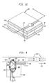
- Figure 1a is a cross-sectional perspective view of a thin film magnetic head 10 with superconducting shielding configured in accordance with the preferred embodiment of the present invention.
- the magnetic head 10 has a principal plane b-b which is perpendicular to the plane of the drawing and which is perpendicular to the principal plane of a magnetic recording medium 12 such as a magnetic disk or magnetic tape.
- a cross-sectional view of the head taken along plane b-b is presented as Figure 1b.
- Figure 1b illustrates the arrangement of a spiral conductor used in both a prior art thin film magnetic recording head and in the thin film recording head of a preferred embodiment of the present invention.
- a plane view of the device of Figure 1a, taken along plane c-c is presented as Figure 1c.
- the thin film magnetic recording head has a core 13 which may consist of a first layer 14 of ferromagnetic alloy, such as permalloy, and a second layer of such material 16. These two layers may be in direct contact with one another in the area identified by numeral 18. As one moves toward the magnetic recording medium 12, the layers 14 and 16 separate to provide a region for a conductor array or coil 20 between the layers.
- the conductor array or coil may be formed on a silicon or ceramic substrate 21 and may be separated from the core by organic or inorganic insulators. Moving closer yet to the magnetic recording medium 12, the layers 14 and 16 are located closer together to define a gap 22.
- the structure of the prior art gap region is best illustrated with reference to Figure 1d.
- the first core layer 14 and second core layer 16 come together to define gap 22.
- Pole portions 24 and 26 of each of the layers of the core are separated by a non-magneticmaterial 23 in the gap, such as SiO2 or Al2O3 and together constitute a throat portion of the head.
- the linear dimension of the throat in a direction perpendicular to the direction of motion of the recording medium is indicated by the dimension D in Figure 1d.
- the linear dimension of the throat in a direction parallel to the motion of the recording medium is indicated by the dimension L (gap length) in Figure 1d and is typically of the order of one micron.
- the various constituent layers 14, 16, 20, 21 and 23 may be formed as thin films using conventional deposition and photolithographic technology.
- the throat depth D has been reduced to the minimum possible length, advantageously less than 25 microns. Otherwise the magnetic energy generated in the head will be largely dissipated through magnetic flux between the pole portions 24 and 26 in the gap.
- the reduction of the throat depth D permits a greater amount of the magnetic flux in the system to appear as a fringing flux indicated by the arrows identified by the numeral 28.
- data may be recorded on or played back from the magnetic recording medium 12.
- an electric current may be applied to the conductor 20 in a direction generally perpendicular to the plane of Figure 1a, as indicated by the arrow head 30. This current may induce a flux in the core of the recording head as indicated by arrows 32.
- a fringing flux 34 may be produced in the vicinity of a local region in the recording medium 12.
- Successive application of current to the recording head and movement of the magnetic recording head and movement of the magnetic recording medium in the direction indicated by the arrow 36 may be used to produce the pattern of magnetization in the medium as in this pattern of magnetization.
- patterns of magnetization sequentially move past the gap 22 of the magnetic recording head.
- a demagnetizing field extending above the recording medium, produces a flux in the core of the recording head and induces a voltage in the conductor 20.
- This induced voltage in the conductor may be employed as a signal indicative of the data encoded in the magnetic recording medium.
- the embodiment of the present invention illustrated in Figures 1a, 1c and 1e employs one or more superconductor shields to produce higher flux densities and improve the efficiency and manufacturability of the thin film magnetic recording head.
- the separation between the layers of core material 14 and 16 narrows in a gap region of the magnetic head defined by pole portions 40 and 42.
- a layer of superconductor material 44 is located in the gap region.
- layers of superconducting material 46 and 48 are located on faces of the pole portions 40 and 42 opposite the gap 22. In the is configuration the pole portions are shielded except for their exposed surfaces or tips and the magnetic flux lines are shunted across the gap into the plane of the recording medium.
- the gap has an extremely high reluctance
- the gap depth becomes a much less critical parameter in the efficiency of the head.
- manufacturing yield should increase significantly.
- the inductance of this head will be lower than that of a typical prior art thin film head. This allows much higher signal bandwidth.
- the thickness of core layer 14 is reduced in the throat region of the magnetic head. This region of reduced thickness constitutes the pole portion of the core layer 14.
- the layer of superconducting material 46 which lies on the face of the layer 14 opposite the gap, tends to concentrate the fringing field of the head at the exposed tip 50 of the trailing pole portion 40 thereby restricting spreading of magnetization of the magnetic medium in the direction of movement of the medium.
- Figure 1c illustrates the structure of the face of the magnetic recording head of Figure 1a.
- the pole portions 40 and 42 are illustrated along with the layers of superconducting shielding material 44, 46 and 48, described above.
- superconducting material is located adjacent to edges 52 of the pole tips. The provision of the superconductor material on the edges of the pole portions of the core tends to reduce intertrack cross-talk and to concentrate the fringing field of the magnetic head in the desired small portion of the magnetic recording medium.
- the superconductor layers are made of a high temperature superconductor such as a yttrium barium copper oxide superconductor material which may exhibit the Meissner effect at the ambient temperature of the head without requiring direct contact with cryogenic liquified gases.
- a high temperature superconductor such as a yttrium barium copper oxide superconductor material which may exhibit the Meissner effect at the ambient temperature of the head without requiring direct contact with cryogenic liquified gases.
- a high temperature superconductor such as a yttrium barium copper oxide superconductor material which may exhibit the Meissner effect at the ambient temperature of the head without requiring direct contact with cryogenic liquified gases.
- FIG. 1e An alternative embodiment employing a lower temperature superconductor material is illustrated in Figure 1e.
- the throat region of the magnetic tape head is illustrated.
- walls 54 and 56 Adjacent the superconductor layers 46 and 48, walls 54 and 56 may be provided for confining a refrigerant.
- the walls 54 and 56 are formed from layers having regions 58 and 60 etched therein.
- the core and superconductor shields are located between the walls 54 and 56.
- a cryogenic liquid may be introduced into regions 58 and 60 of the structure of Figure 1e to maintain the superconducting layers of the head at a temperature where the superconductor materials exhibit the Meissner effect.
- liquid nitrogen may be supplied to the regions 58 and 60 to provide adiabatic cooling of the superconductors.
- Walls 54 and 56 prevent the refrigerant from contacting the recording medium.
- the playback preamplifiers that are employed in magnetic reproduction machines exhibit thermal noise.
- the preamplifier can be located in an area that is cooled by the cryogenic liquid, to thereby reduce the noise inherent to these devices.
- the depth of the throat D of the magnetic head is not a critical dimension.
- a planar surface 62 which is disposed adjacent the magnetic recording material may be formed by lapping the edge of the thin film recording head. It will be understood that the exact amount of material removed in the lapping process is not important because the dimension D of the throat is not critical to the performance of the magnetic head in this embodiment of the present invention. In addition, because a greater throat depth can be tolerated, it is possible to provide members 54 and 56 and channels 58 and 60 to introduce a cryogenic refrigerant in the vicinity of the gap to maintain the superconducting material at the requisite temperature.
- Figures 2a and 2b illustrate a multi-track magnetic head constituting another embodiment of the invention.
- Multi-track heads are known in the prior art. In such heads a plurality of magnetic cores are arrayed adjacent one another. To reduce cross-talk caused by flux leakage (interhead coupling) in the prior art, magnetic shielding was sometimes provided between the cores. In one prior art embodiment, a copper laminated magnetic shielding was provided between the respective multi-track cores. To prevent the shields from shorting the gap flux of the cores, a nonconducting ceramic fillet was provided to separate the shield from the respective cores between which it was positioned. This prior art arrangement had the disadvantage that it did not sufficiently reduce cross-talk caused by flux leakage for all applications. In addition, the copper shields are soft in comparison to the cores and ceramic fillets used to make up the head. This in turn caused uneven machining of the head and uneven wear during use.
- FIG. 2a Another embodiment of a multi-track magnetic head shown in Figure 2a and is denoted by the numeral 70.
- the head consists of a plurality of magnetic cores 72 each having an electrical conductor or coil 74 associated therewith.
- adjacent cores are separated by a ceramic superconductor inter-track shield 76.
- These shields may be separated from the core 72 by a lanthanum titanate or similar ceramic fillet as shown in Figures 2a and 2b or the cores can be put in direct contact with the superconductor since the superconductor excludes the magnetic field and would therefore not short the gap flux of the cores.
- a face of the magnetic recording head adapted to be disposed adjacent to the magnetic recording material is shown in plan view of Figure 2b.
- Each core 72 is associated with a track illustrated schematically at numerals 78.
- a fringing field produced at gaps 80 of the core 72 may be used to selectively magnetize the recording material to impart data onto the tracks 78.
- the intertrack shields 76 exclude magnetic flux and thereby reduce cross-talk between the cores 72 of the multi-track head. This in turn permits the use of narrower tracs, and consequently, the recording of a higher density of data on the magnetic medium.
- an outer box shield 82 of superconductor material may be provided.
- the shield layers 82 may be formed on surfaces such as surface 84 and surface 86 which extend away from the recording medium.
- the superconductor shields employed in the device of Figures 2a and 2b can be fabricated in thin layers by conventional hot pressing, dicing and grinding technology used in ceramic fabrication.
- the heads can be assembled by alternating superconductor shield layers, ceramic spacers or shims, and the cores to form magnetic head stacks.
- Figure 2c illustrates the use of shielding techniques employed in the multi-track head of Figures 2a and 2b in the production of a zero side-reading head 90.
- a head is useful in applications where narrow, closely spaced tracks are employed. In such environments, the head may tend to link with flux from adjacent tracks in playback operations.
- superconductor material layers 92 and 94 are placed on either side of the core 96.
- a coil 97 is wrapped around core poles 99 and the associated layers of superconductor material.
- the superconductor layers will reject all flux from the adjacent tracks thereby eliminating the side reading effect. In addition, the superconductor layers will reduce the leakage of flux from the head gap 98 and result in lower inductance.
- Figure 3 depicts a ring head for longitudinal recording employing a pole shield of superconducting material in accordance with another embodiment of the present invention.
- a core 100 is provided having a magnetic flux path indicated by arrows 102 which is closed except for a gap 104.
- the gap 104 lies between a leading pole portion 106 and a trailing pole portion 108 of the core.
- Each of the pole portions 106 and 108 has a surface, 110 and 112, respectively, in generally the same plane, the surfaces 110 and 112 being adapted for positioning adjacent the magnetic medium.
- a conductor, in the form of a coil of wire 113, is provided for inducing a magnetic flux in the core in response to an electric current applied to the conductor.
- a pole shield 114 made of superconductor material is provided on the trailing portion of the core.
- the pole shield 114 has a surface 116 which is in the plane of the pole surfaces 110 and 112. Additionally, the pole shield 114 is adapted to be located between the recording medium 115 and the bulk of the trailing pole portion 108 except for an exposed trailing pole tip 118 whose surface is indicated by the numeral 112.
- the magnetic field of the head is concentrated at the trailing pole tip 118 as indicated by the arrows. This restricts the spreading of magnetization of the magnetic medium in the direction of movement of the medium, indicated by arrow 119. As a result the recording field sharply decays at the trailing pole tip 118 and is capable of producing higher degree of definition between areas of magnetization 121 on the recording medium as the recording medium passes away from the head.
- the length of the trailing pole surface 112 i.e., its linear dimension in the direction of motion of the recording medium
- the corresponding length of the leading pole surface 110 may be 50 times that of the trailing pole surface 112.
- Figure 4 illustrates a probe magnetic head known in the prior art for perpendicular recording.
- a vertical recording field 120 is produced by the recording head 122.
- the vertical recording field impinges upon a recording medium 124 and may be employed to induce magnetization in selected regions of the recording material 124.
- An example of the vertical orientation of the magnetization of the recording medium is illustrated by the arrows 126 in Figure 4.
- a coil 128 and core 130 are employed as indicated. Between halves of the core a probe member 132 is positioned. The probe member 132 tends to concentrate the fringing field of the head outward from the face of the head into the magnetic recording medium to facilitate perpendicular recording.
- the head includes superconductor shields 140, 142 and 144 having exposed surfaces lying adjacent the recording medium.
- the Meissner effect of the superconductor layers confines the head flux to the probe member 138 and to a small region 146 of the pole portion 148 of the core. This provides a substantially vertical field in the vicinity of the recording media while maintaining an efficient flux closure path.
- Figure 6 illustrates another embodiment of the present invention.
- a magnetic head 150 for longitudinal recording includes core halves 152 and 154 separated at a gap 156 and a coil 158, electromagnetically coupled to the core.
- low frequency modulations head bumps
- flux adds to the gap flux, either constructively or destructively, producing unwanted modulation.
- superconductor pole tips 160 and 162 are placed on the core to prevent "head bumps”.
- Surfaces 164 and 166 of the pole halves 152 and 154 closest to the recording medium 168 are chamfered so that the surfaces slope away from the plane e-e of the recording medium as the distance from the gap 156 increases.
- the chamfered surfaces 164 and 166 are covered by the superconductor pole tip shield 160 and 162, respectively whose thickness decreases as one moves toward the gap.
- Narrow regions 170 of the pole halves 152 and 154 are exposed adjacent the gap.
- the magnetic field of the head is concentrated in the narrow exposed regions 170 of the core, so that the tape flux is coupled to the core only at the gap area.
- the flux coupling to other parts of the core is virtually eliminated and a smoother low frequency response results.
Landscapes
- Engineering & Computer Science (AREA)
- Manufacturing & Machinery (AREA)
- Physics & Mathematics (AREA)
- Electromagnetism (AREA)
- Magnetic Heads (AREA)
Applications Claiming Priority (2)
| Application Number | Priority Date | Filing Date | Title |
|---|---|---|---|
| US07/265,620 US5075280A (en) | 1988-11-01 | 1988-11-01 | Thin film magnetic head with improved flux concentration for high density recording/playback utilizing superconductors |
| US265620 | 1988-11-01 |
Publications (2)
| Publication Number | Publication Date |
|---|---|
| EP0367439A2 true EP0367439A2 (de) | 1990-05-09 |
| EP0367439A3 EP0367439A3 (de) | 1991-11-13 |
Family
ID=23011210
Family Applications (1)
| Application Number | Title | Priority Date | Filing Date |
|---|---|---|---|
| EP19890310623 Withdrawn EP0367439A3 (de) | 1988-11-01 | 1989-10-17 | Magnetkopf mit supraleitenden Abschirmungen |
Country Status (3)
| Country | Link |
|---|---|
| US (1) | US5075280A (de) |
| EP (1) | EP0367439A3 (de) |
| JP (1) | JPH02162510A (de) |
Families Citing this family (18)
| Publication number | Priority date | Publication date | Assignee | Title |
|---|---|---|---|---|
| US5379018A (en) * | 1989-01-27 | 1995-01-03 | Rockwell International Corporation | High temperature superconductor magnetic-switch |
| US5541563A (en) * | 1995-01-11 | 1996-07-30 | The United States Of America As Represented By The Secretary Of The Army | Magnet iron structure |
| US5717552A (en) * | 1996-09-10 | 1998-02-10 | Ampex Corporation | Magnetic core with field confinement structure |
| US6031695A (en) * | 1997-09-05 | 2000-02-29 | International Business Machines Corporation | Combined read head and write head with non-magnetic electrically conductive layer on upper pole tip thereof |
| US6111724A (en) * | 1998-04-10 | 2000-08-29 | International Business Machines Corporation | Method of making a magnetic write head with plated self-aligned zero throat height defining layer without reflective notching of a second pole tip |
| JP3373181B2 (ja) * | 1999-09-17 | 2003-02-04 | ティーディーケイ株式会社 | 薄膜磁気ヘッドおよびその製造方法 |
| US6667848B1 (en) * | 2000-01-10 | 2003-12-23 | Seagate Technology Llc | Perpendicular magnetic recording head with means for suppressing noise from soft magnetic underlayer of recording media |
| JP3593312B2 (ja) * | 2000-12-26 | 2004-11-24 | アルプス電気株式会社 | 垂直磁気記録ヘッドおよびその製造方法 |
| US6687085B2 (en) * | 2001-07-17 | 2004-02-03 | Seagate Technology Llc | Perpendicular write head with high magnetization pole material and method of fabricating the write head |
| DE10345043A1 (de) | 2003-09-27 | 2005-04-21 | Rhein Chemie Rheinau Gmbh | Mikrogel-enthaltende Zusammensetzung |
| US7599152B2 (en) * | 2005-04-28 | 2009-10-06 | Headway Technologies, Inc. | Magnetic read-write head shield that prevents flux concentration at edges close to the ABS |
| US20060245113A1 (en) * | 2005-04-28 | 2006-11-02 | Headway Technologies, Inc. | Method to reduce sensitivity of a perpendicular recording head to external fields |
| US7538976B2 (en) * | 2006-04-25 | 2009-05-26 | Hitachi Global Storage Technologies B.V. | Trailing shield design for reducing wide area track erasure (water) in a perpendicular recording system |
| US7768741B2 (en) * | 2006-05-22 | 2010-08-03 | Hitachi Global Storage Technologies Netherlands B.V. | Magnetic write head design for reducing wide area track erasure |
| US8804283B2 (en) | 2011-06-22 | 2014-08-12 | Seagate Technology Llc | Chamfered magnetic write pole |
| US9142226B2 (en) * | 2012-06-29 | 2015-09-22 | Seagate Technology Llc | Thin film with tuned grain size |
| US8837084B2 (en) | 2012-11-29 | 2014-09-16 | HGST Netherlands B.V. | Perpendicular magnetic write head having a hull shaped stitched pole |
| US11031032B1 (en) | 2017-04-03 | 2021-06-08 | Seagate Technology Llc | Cryogenic magnetic alloys with less grain refinement dopants |
Family Cites Families (26)
| Publication number | Priority date | Publication date | Assignee | Title |
|---|---|---|---|---|
| US2966647A (en) * | 1959-04-29 | 1960-12-27 | Ibm | Shielded superconductor circuits |
| NL231789A (de) * | 1957-09-30 | |||
| US3156850A (en) * | 1958-12-31 | 1964-11-10 | Texas Instruments Inc | Method of providing a regulated magnetic field |
| US3361940A (en) * | 1959-09-29 | 1968-01-02 | Rand Corp | Process of forming a super-conductive magnetic shield |
| US3098181A (en) * | 1960-08-29 | 1963-07-16 | Bell Telephone Labor Inc | Magnetic circuit using superconductor properties |
| US3187229A (en) * | 1961-11-01 | 1965-06-01 | Bell Telephone Labor Inc | Superconducting magnet utilizing superconductive shielding at lead junctions |
| NL297703A (de) * | 1962-09-25 | |||
| NL300191A (de) * | 1962-11-29 | |||
| US3234435A (en) * | 1963-07-09 | 1966-02-08 | Bell Telephone Labor Inc | Magnetic field stabilizer for a superconductive device |
| US3378691A (en) * | 1963-09-26 | 1968-04-16 | Gen Electric | Superconductive shield |
| US3253193A (en) * | 1963-10-21 | 1966-05-24 | Westinghouse Electric Corp | Superconducting means for concentrating magnetic flux |
| US3384809A (en) * | 1964-07-17 | 1968-05-21 | Burroughs Corp | Controlled inductance device utilizing an apertured superconductive plane |
| GB1121559A (en) * | 1965-12-10 | 1968-07-31 | Gen Electric Co Ltd | Improvements in or relating to methods of and apparatus for the production of magnetic fields using superconducting magnets |
| DE1522971A1 (de) * | 1967-03-29 | 1969-10-30 | Altenkirch Karl Adolf | Gegenstand der Erfindung ist ein Verfahren zur Verbesserung der Dynamik und des Stoerabstandes eines Magnettonkopfes vermittels Schraeganordnung des Spaltes und Verwendung diamagnetischer Stoffe |
| JPS57120221A (en) * | 1981-01-14 | 1982-07-27 | Seiko Epson Corp | Ring head for vertical magnetization recording and reproduction |
| JPS60151315A (ja) * | 1984-01-18 | 1985-08-09 | Nippon Ester Co Ltd | ポリエステル原着糸の製造法 |
| JPS63249983A (ja) * | 1987-04-06 | 1988-10-17 | Hitachi Ltd | 磁気記録装置 |
| JPS63251905A (ja) * | 1987-04-08 | 1988-10-19 | Hitachi Ltd | 磁気ヘツド |
| JPS63253509A (ja) * | 1987-04-10 | 1988-10-20 | Hitachi Ltd | 磁電変換装置 |
| JPS63259817A (ja) * | 1987-04-17 | 1988-10-26 | Matsushita Electric Ind Co Ltd | 薄膜磁気ヘツド |
| JPS63259813A (ja) * | 1987-04-17 | 1988-10-26 | Matsushita Electric Ind Co Ltd | 薄膜磁気ヘツド |
| JPS63263620A (ja) * | 1987-04-21 | 1988-10-31 | Mitsubishi Electric Corp | 記録又は再生用磁気ヘツド |
| NL8701667A (nl) * | 1987-07-15 | 1989-02-01 | Philips Nv | Dunne film transformator en magneetkop voorzien van een dergelijke transformator. |
| NL8701664A (nl) * | 1987-07-15 | 1989-02-01 | Philips Nv | Dunne film magneetkop met inductief overdrachtselement. |
| FR2622341A1 (fr) * | 1987-10-27 | 1989-04-28 | Thomson Csf | Tete magnetique d'enregistrement/lecture comportant un materiau supraconducteur |
| JPH01211205A (ja) * | 1988-02-17 | 1989-08-24 | Fujitsu Ltd | 磁気記録再生用磁気ヘッド |
-
1988
- 1988-11-01 US US07/265,620 patent/US5075280A/en not_active Expired - Lifetime
-
1989
- 1989-10-17 EP EP19890310623 patent/EP0367439A3/de not_active Withdrawn
- 1989-10-31 JP JP1284636A patent/JPH02162510A/ja active Pending
Also Published As
| Publication number | Publication date |
|---|---|
| US5075280A (en) | 1991-12-24 |
| EP0367439A3 (de) | 1991-11-13 |
| JPH02162510A (ja) | 1990-06-22 |
Similar Documents
| Publication | Publication Date | Title |
|---|---|---|
| US5075280A (en) | Thin film magnetic head with improved flux concentration for high density recording/playback utilizing superconductors | |
| US5296993A (en) | Magnetic head with magnetic substrate and an enhanced poletip thereon | |
| US5394285A (en) | Multi-track longitudinal, metal-in-gap head | |
| US6801379B2 (en) | Multi-magnetic recording head, and magnetic recording method and magnetic recording apparatus using the same | |
| EP0675486A2 (de) | Magnetoresistiver Wandler mit integriertem Joch und magnetischem Nebenschluss | |
| US5423116A (en) | Method of manufacturing a multi-track longitudinal, metal-in-gap head | |
| US5153798A (en) | Magnetic head including a core having a non-magnetic gap | |
| EP0531516B1 (de) | Dünnfilmlaminierter aufnahme/wiedergabe magnetkopf für hohe schreibdichten und datentransferraten | |
| US4907115A (en) | Super conducting thin-film magnetic head including a magnetoresistive element | |
| JPH01165010A (ja) | 複合型磁気ヘッド | |
| Brock et al. | Batch-fabricated heads from an operational standpoint | |
| JPH0319119A (ja) | 浮動型磁気ヘッド | |
| JPS63317910A (ja) | 磁気ヘッド | |
| KR100244187B1 (ko) | 복합 자기헤드 및 그 제조방법 | |
| JPS63259813A (ja) | 薄膜磁気ヘツド | |
| JPH079204Y2 (ja) | 磁気ヘツド | |
| JPH01199311A (ja) | 薄膜磁気ヘッド | |
| JPS63311606A (ja) | 垂直磁気ヘッド | |
| JPH01158608A (ja) | 浮動型磁気ヘッド | |
| JPS62145512A (ja) | 磁気消去ヘツド | |
| JPS61168117A (ja) | 磁気ヘツド | |
| JPH05325140A (ja) | 複合型薄膜磁気ヘッド | |
| JPH0684157A (ja) | 磁気ヘッド | |
| JPH0278003A (ja) | 垂直記録磁気ヘッド | |
| JPH0415523B2 (de) |
Legal Events
| Date | Code | Title | Description |
|---|---|---|---|
| PUAI | Public reference made under article 153(3) epc to a published international application that has entered the european phase |
Free format text: ORIGINAL CODE: 0009012 |
|
| AK | Designated contracting states |
Kind code of ref document: A2 Designated state(s): CH DE FR LI NL |
|
| PUAL | Search report despatched |
Free format text: ORIGINAL CODE: 0009013 |
|
| AK | Designated contracting states |
Kind code of ref document: A3 Designated state(s): CH DE FR LI NL |
|
| 17P | Request for examination filed |
Effective date: 19920123 |
|
| 17Q | First examination report despatched |
Effective date: 19930512 |
|
| STAA | Information on the status of an ep patent application or granted ep patent |
Free format text: STATUS: THE APPLICATION HAS BEEN WITHDRAWN |
|
| RAP1 | Party data changed (applicant data changed or rights of an application transferred) |
Owner name: AMPEX SYSTEMS CORPORATION |
|
| 18W | Application withdrawn |
Withdrawal date: 19940221 |