EP0367448A1 - Ventilsteuerungsvorrichtung für Brennkraftmaschinen - Google Patents
Ventilsteuerungsvorrichtung für Brennkraftmaschinen Download PDFInfo
- Publication number
- EP0367448A1 EP0367448A1 EP89310746A EP89310746A EP0367448A1 EP 0367448 A1 EP0367448 A1 EP 0367448A1 EP 89310746 A EP89310746 A EP 89310746A EP 89310746 A EP89310746 A EP 89310746A EP 0367448 A1 EP0367448 A1 EP 0367448A1
- Authority
- EP
- European Patent Office
- Prior art keywords
- internal combustion
- engine
- combustion engine
- intake
- control system
- Prior art date
- Legal status (The legal status is an assumption and is not a legal conclusion. Google has not performed a legal analysis and makes no representation as to the accuracy of the status listed.)
- Granted
Links
Images

Classifications
-
- F—MECHANICAL ENGINEERING; LIGHTING; HEATING; WEAPONS; BLASTING
- F02—COMBUSTION ENGINES; HOT-GAS OR COMBUSTION-PRODUCT ENGINE PLANTS
- F02D—CONTROLLING COMBUSTION ENGINES
- F02D13/00—Controlling the engine output power by varying inlet or exhaust valve operating characteristics, e.g. timing
- F02D13/02—Controlling the engine output power by varying inlet or exhaust valve operating characteristics, e.g. timing during engine operation
- F02D13/0253—Fully variable control of valve lift and timing using camless actuation systems such as hydraulic, pneumatic or electromagnetic actuators, e.g. solenoid valves
-
- F—MECHANICAL ENGINEERING; LIGHTING; HEATING; WEAPONS; BLASTING
- F01—MACHINES OR ENGINES IN GENERAL; ENGINE PLANTS IN GENERAL; STEAM ENGINES
- F01L—CYCLICALLY OPERATING VALVES FOR MACHINES OR ENGINES
- F01L9/00—Valve-gear or valve arrangements actuated non-mechanically
- F01L9/20—Valve-gear or valve arrangements actuated non-mechanically by electric means
-
- F—MECHANICAL ENGINEERING; LIGHTING; HEATING; WEAPONS; BLASTING
- F02—COMBUSTION ENGINES; HOT-GAS OR COMBUSTION-PRODUCT ENGINE PLANTS
- F02D—CONTROLLING COMBUSTION ENGINES
- F02D13/00—Controlling the engine output power by varying inlet or exhaust valve operating characteristics, e.g. timing
- F02D13/02—Controlling the engine output power by varying inlet or exhaust valve operating characteristics, e.g. timing during engine operation
- F02D13/0203—Variable control of intake and exhaust valves
-
- F—MECHANICAL ENGINEERING; LIGHTING; HEATING; WEAPONS; BLASTING
- F02—COMBUSTION ENGINES; HOT-GAS OR COMBUSTION-PRODUCT ENGINE PLANTS
- F02D—CONTROLLING COMBUSTION ENGINES
- F02D17/00—Controlling engines by cutting out individual cylinders; Rendering engines inoperative or idling
- F02D17/02—Cutting-out
-
- F—MECHANICAL ENGINEERING; LIGHTING; HEATING; WEAPONS; BLASTING
- F02—COMBUSTION ENGINES; HOT-GAS OR COMBUSTION-PRODUCT ENGINE PLANTS
- F02D—CONTROLLING COMBUSTION ENGINES
- F02D41/00—Electrical control of supply of combustible mixture or its constituents
- F02D41/008—Controlling each cylinder individually
- F02D41/0087—Selective cylinder activation, i.e. partial cylinder operation
-
- F—MECHANICAL ENGINEERING; LIGHTING; HEATING; WEAPONS; BLASTING
- F01—MACHINES OR ENGINES IN GENERAL; ENGINE PLANTS IN GENERAL; STEAM ENGINES
- F01L—CYCLICALLY OPERATING VALVES FOR MACHINES OR ENGINES
- F01L2201/00—Electronic control systems; Apparatus or methods therefor
-
- F—MECHANICAL ENGINEERING; LIGHTING; HEATING; WEAPONS; BLASTING
- F02—COMBUSTION ENGINES; HOT-GAS OR COMBUSTION-PRODUCT ENGINE PLANTS
- F02D—CONTROLLING COMBUSTION ENGINES
- F02D41/00—Electrical control of supply of combustible mixture or its constituents
- F02D41/0002—Controlling intake air
- F02D2041/001—Controlling intake air for engines with variable valve actuation
-
- F—MECHANICAL ENGINEERING; LIGHTING; HEATING; WEAPONS; BLASTING
- F02—COMBUSTION ENGINES; HOT-GAS OR COMBUSTION-PRODUCT ENGINE PLANTS
- F02D—CONTROLLING COMBUSTION ENGINES
- F02D41/00—Electrical control of supply of combustible mixture or its constituents
- F02D41/0002—Controlling intake air
- F02D2041/001—Controlling intake air for engines with variable valve actuation
- F02D2041/0012—Controlling intake air for engines with variable valve actuation with selective deactivation of cylinders
-
- Y—GENERAL TAGGING OF NEW TECHNOLOGICAL DEVELOPMENTS; GENERAL TAGGING OF CROSS-SECTIONAL TECHNOLOGIES SPANNING OVER SEVERAL SECTIONS OF THE IPC; TECHNICAL SUBJECTS COVERED BY FORMER USPC CROSS-REFERENCE ART COLLECTIONS [XRACs] AND DIGESTS
- Y02—TECHNOLOGIES OR APPLICATIONS FOR MITIGATION OR ADAPTATION AGAINST CLIMATE CHANGE
- Y02T—CLIMATE CHANGE MITIGATION TECHNOLOGIES RELATED TO TRANSPORTATION
- Y02T10/00—Road transport of goods or passengers
- Y02T10/10—Internal combustion engine [ICE] based vehicles
- Y02T10/12—Improving ICE efficiencies
Definitions
- the present invention relates to a valve control system for electromagnetically actuating intake and exhaust valves of an internal combustion engine.
- Intake and exhaust valves of an internal combustion engine are generally opened and closed by a valve operating mechanism according to a cam profile of a camshaft which rotates in synchronism with the crankshaft of the engine.
- Various arrangements for stopping the operation of some intake and exhaust valves have been proposed. According to one design, the operation of an intake or exhaust valve is stopped by moving the fulcrum of a rocker arm which transmits the motion of a cam to the valve. According to another scheme, the operation of an intake or exhaust valve is stopped by releasing hydraulic pressure from a hydraulic tappet.
- valve disabling devices are structurally complex, and are not satisfactorily reliable when the valve is to be disabled while the engine is in operation.
- Another object of the present invention is to provide a control system for controlling the intake and exhaust valves of an internal combustion engine, which control system being arranged to prevent lubricating oil from remaining the cylinders by successively disabling the cylinders each time the engine makes a predetermined number of rotations.
- a control system for controlling intake and exhaust valves of an internal combustion engine comprising electromagnetic actuator means for opening and closing the intake and exhaust valves, control means for applying drive signals to the electromagnetic actuator means, an engine speed sensor for detecting the rotational speed of the internal combustion engine, an accelerator pedal movement sensor for detecting the amount of depression of an accelerator pedal which controls a load on the internal combustion engine, and cylinder control means for determining that the internal combustion engine is idling and cutting off drive signals to the electromagnetic actuator means for selected cylinders of the internal combustion engine, when the engine speed based on a detected signal from the engine speed sensor is lower than a preset speed and the amount of depression of the accelerator pedal based on a detected signal from the accelerator pedal movement sensor is smaller than a preset amount.
- FIGS. 1 and 2 show a valve control system for an internal combustion engine according to the present invention.
- an internal combustion engine 1 which is shown as a four-cylinder engine in this embodiment, has an intake valve 8 and an exhaust valve 9 in each of the cylinders. Expansive forces produced by burning fuel in each of the cylinders are transmitted from a piston 3 through a connecting rod 4 to a crankshaft 2 to rotate the crankshaft 2 about its own axis.
- the rotative power transmitted to the crankshaft 2 is transmitted through power transmitting mechanisms such as a clutch 5, a transmission 6, etc. to road wheels 7 to propel a motor vehicle on which the engine 1 is mounted.
- the amount by which an accelerator pedal 11 is depressed by an accelerator pedal movement sensor 10, and the rotational speed of the engine 1 is detected by an engine speed sensor 55.
- Detected signals from these sensors are supplied to a control unit 56.
- the control unit 56 produces a drive signal based on the detected signals from the sensors 11, 55, and applies the produced drive signal to valve actuator means for actuating the intake and exhaust valves 8, 9.
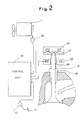
- the valve actuator means for actuating the intake valve 8 will be described below with reference to FIG. 2.
- the intake valve 8 is made of a ceramic material such as silicon nitride or silicon carbide, and is slidably fitted in a valve guide 51 mounted in a cylinder head and made of a ceramic material such as silicon nitride or silicon carbide.
- a movable member 57 of a magnetic material is fixedly fitted over the upper end of the stem of the intake valve 8.
- An upper electromagnet 52 and a lower electromagnet 53 are disposed above and below, respectively, the movable member 57 in spaced-apart relation thereto.
- a coil spring 58 for normally urging the intake valve 8 to close the intake port so that the intake valve 8 is prevented from being unseated when the upper and lower electromagnets 52, 53 are de-energized.
- the coil of the upper electromagnet 52 When the valve 8 is closed, the coil of the upper electromagnet 52 is continuously energized to attract the movable member 57 upwardly, thereby keeping the valve 8 closed.
- the coil of the upper electro-magnet 52 is de-energized to release the movable member 57 off the upward attractive force, and the coil of the lower electromagnet 53 is simultaneously energized to produce a downward attractive force.
- the movable member 57 is therefore attracted to the lower electromagnet 53 to move the valve 8 downwardly, thus opening the intake port.
- the coil of the lower electromagnet 53 is de-energized to free the movable member 57 from the downward attractive force and the coil of the upper electromagnet 52 is energized to attract the movable member 57 upwardly.
- valve control system of the present invention will be described below.
- the control unit 56 determines, from the detected signals from the engine speed sensor 55 and the accelerator pedal movement sensor 10, that the engine is idling, and controls the engine cylinders, when the engine speed is lower than a predetermined speed and the amount of depression of the accelerator pedal 11 is smaller than a predetermined amount.
- the four-cycle four-cylinder engine burns fuel successively in the first, second, third, and fourth cylinders, in the order named, each times the crankshaft 2 makes half of one rotation.
- the valve control system of the present invention first enables the first and fourth cylinders only, and then enables the second and third cylinders only after the crankshaft 2 has made a certain number of rotations.
- the valve control system operates the engine cyclically between a mode in which only the first and fourth cylinders are enabled and a mode in which only the second and third cylinders are enabled.
- the cylinders are successively enabled in this manner in order to prevent lubricating oil from remaining in those cylinders which are disabled and also to uniformize wear of the cylinders.
- An engine cylinder is disabled by stopping the operation of the intake and exhaust valves of the cylinder and cutting off fuel supply to the cylinder.
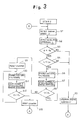
- control unit 56 A control sequence executed by the control unit 56 will be described below with reference to FIG. 3.
- the control unit 56 reads an engine speed N detected by the engine speed sensor 55 in a step 1, and reads an amount of depression L of the accelerator pedal 11 detected by the accelerator pedal movement sensor 10 in a step 2. Then, the control unit 56 compares the engine speed N and a preset speed Na in a step 3. If the engine speed N is lower than the preset speed Na, then the control unit 56 compares the amount of depression L with a preset amount of depression La in a step 4. If the amount of depression L is smaller than the preset amount of depression La, then the control unit 56 determines that the engine is idling, and control goes to a step 6 for cylinder control.
- control system 56 determines that the engine is not idling, and control goes to a step 5 in which the engine is operated normally.
- step 6 only the first and fourth cylinders of the engine are enabled by cutting off drive signals applied to the lower electromagnets 53 of the valve actuator means for the second and third cylinders.
- the number n of accumulated rotations of the engine is counted in a step 7, which is followed by a step 8 which determines whether the number n of accumulated engine rotations has reached a preset count n1 or not. If the number n of accumulated engine rotations is smaller than the present count n1, then the first and fourth cylinders remain enabled until the number n of accumulated engine rotations reaches the preset count n1.
- control proceeds to a step 9 in which the counter for counting the number of accumulated engine rotations is reset. Then, control goes to a step 10 in which only the second and third cylinders are enabled in a step 10. More specifically, the drive signals applied to the lower electromagnets 53 of the valve actuator means for the first and fourth cylinders are cut off, and drive signals are applied to the upper and lower electromagnets 52, 53 of the valve actuator means for the second and third cylinders. The second and third cylinders remain enabled until the number n of accumulated engine rotations reaches the preset count n1 (see steps 10 and 11). After the number n of accumulated engine rotations has reached the preset count n1 (see a step 12), the counter is reset in a step 13, and the process from the step 1 is repeated.
- the intake and exhaust valves are made of a ceramic material, they are lighter than metallic valves, and are subjected to smaller forces of inertia during operation. Accordingly, the intake and exhaust valves operate smoothly, and the forces required by the electromagnetic actuator means to actuate the valves may be reduced.
Landscapes
- Engineering & Computer Science (AREA)
- Mechanical Engineering (AREA)
- General Engineering & Computer Science (AREA)
- Chemical & Material Sciences (AREA)
- Combustion & Propulsion (AREA)
- Physics & Mathematics (AREA)
- Electromagnetism (AREA)
- Valve Device For Special Equipments (AREA)
- Output Control And Ontrol Of Special Type Engine (AREA)
Applications Claiming Priority (2)
| Application Number | Priority Date | Filing Date | Title |
|---|---|---|---|
| JP275308/88 | 1988-10-31 | ||
| JP63275308A JPH02123212A (ja) | 1988-10-31 | 1988-10-31 | バルブ制御装置 |
Publications (2)
| Publication Number | Publication Date |
|---|---|
| EP0367448A1 true EP0367448A1 (de) | 1990-05-09 |
| EP0367448B1 EP0367448B1 (de) | 1993-12-15 |
Family
ID=17553628
Family Applications (1)
| Application Number | Title | Priority Date | Filing Date |
|---|---|---|---|
| EP89310746A Revoked EP0367448B1 (de) | 1988-10-31 | 1989-10-19 | Ventilsteuerungsvorrichtung für Brennkraftmaschinen |
Country Status (4)
| Country | Link |
|---|---|
| US (1) | US4976228A (de) |
| EP (1) | EP0367448B1 (de) |
| JP (1) | JPH02123212A (de) |
| DE (1) | DE68911484T2 (de) |
Cited By (8)
| Publication number | Priority date | Publication date | Assignee | Title |
|---|---|---|---|---|
| EP0703357A3 (de) * | 1994-09-20 | 1996-07-24 | Honda Motor Co Ltd | Brennkraftmaschine mit Steuerung der Zahl der aktiven Zylinder |
| EP0661427A3 (de) * | 1993-12-23 | 1996-08-28 | Ford Motor Co | Brennkraftmaschine. |
| DE19742969A1 (de) * | 1997-09-29 | 1999-04-08 | Siemens Ag | Verfahren zum Starten einer Mehrzylinderbrennkraftmaschine |
| WO2000026534A1 (de) * | 1998-10-30 | 2000-05-11 | Continental Isad Electronic Systems Gmbh & Co. Ohg | Verbrennungsmotor, insbesondere für ein kraftfahrzeug, sowie verfahren zum starten desselben |
| EP1010865A1 (de) * | 1998-11-19 | 2000-06-21 | Nissan Motor Co., Ltd. | Vorrichtung und Verfahren zur Steuerung einer Brennkraftmaschine |
| WO2000040847A1 (de) * | 1999-01-08 | 2000-07-13 | Siemens Aktiengesellschaft | Verfahren zur wiederinbetriebnahme eines zylinders einer mehrzylindrigen brennkraftmaschine |
| WO2002050406A1 (de) * | 2000-12-21 | 2002-06-27 | Robert Bosch Gmbh | Verfahren und vorrichtung zum betreiben einer brennkraftmaschine |
| EP1361352A4 (de) * | 2001-02-14 | 2005-01-26 | Mikuni Kogyo Kk | Treiber für direkt wirkendes ventil für brennkraftmaschine |
Families Citing this family (37)
| Publication number | Priority date | Publication date | Assignee | Title |
|---|---|---|---|---|
| US5190013A (en) * | 1992-01-10 | 1993-03-02 | Siemens Automotive L.P. | Engine intake valve selective deactivation system and method |
| US5408966A (en) * | 1993-12-23 | 1995-04-25 | Ford Motor Company | System and method for synchronously activating cylinders within a variable displacement engine |
| US5431139A (en) * | 1993-12-23 | 1995-07-11 | Ford Motor Company | Air induction control system for variable displacement internal combustion engine |
| US5398544A (en) * | 1993-12-23 | 1995-03-21 | Ford Motor Company | Method and system for determining cylinder air charge for variable displacement internal combustion engine |
| US5374224A (en) * | 1993-12-23 | 1994-12-20 | Ford Motor Company | System and method for controlling the transient torque output of a variable displacement internal combustion engine |
| US5490486A (en) * | 1994-10-05 | 1996-02-13 | Ford Motor Company | Eight cylinder internal combustion engine with variable displacement |
| US5617829A (en) * | 1995-11-20 | 1997-04-08 | Ford Motor Company | Method for maintaining clean spark plugs in a variable displacement engine |
| JP3846070B2 (ja) * | 1998-10-29 | 2006-11-15 | トヨタ自動車株式会社 | 電磁駆動弁の制御装置 |
| JP3562415B2 (ja) * | 1999-12-24 | 2004-09-08 | トヨタ自動車株式会社 | 可変動弁機構を有する内燃機関 |
| US6931839B2 (en) | 2002-11-25 | 2005-08-23 | Delphi Technologies, Inc. | Apparatus and method for reduced cold start emissions |
| US7107947B2 (en) | 2004-03-19 | 2006-09-19 | Ford Global Technologies, Llc | Multi-stroke cylinder operation in an internal combustion engine |
| US7559309B2 (en) | 2004-03-19 | 2009-07-14 | Ford Global Technologies, Llc | Method to start electromechanical valves on an internal combustion engine |
| US7107946B2 (en) * | 2004-03-19 | 2006-09-19 | Ford Global Technologies, Llc | Electromechanically actuated valve control for an internal combustion engine |
| US7017539B2 (en) | 2004-03-19 | 2006-03-28 | Ford Global Technologies Llc | Engine breathing in an engine with mechanical and electromechanical valves |
| US7240663B2 (en) | 2004-03-19 | 2007-07-10 | Ford Global Technologies, Llc | Internal combustion engine shut-down for engine having adjustable valves |
| US7140355B2 (en) | 2004-03-19 | 2006-11-28 | Ford Global Technologies, Llc | Valve control to reduce modal frequencies that may cause vibration |
| US7066121B2 (en) | 2004-03-19 | 2006-06-27 | Ford Global Technologies, Llc | Cylinder and valve mode control for an engine with valves that may be deactivated |
| US7032545B2 (en) | 2004-03-19 | 2006-04-25 | Ford Global Technologies, Llc | Multi-stroke cylinder operation in an internal combustion engine |
| US7165391B2 (en) | 2004-03-19 | 2007-01-23 | Ford Global Technologies, Llc | Method to reduce engine emissions for an engine capable of multi-stroke operation and having a catalyst |
| US7128043B2 (en) | 2004-03-19 | 2006-10-31 | Ford Global Technologies, Llc | Electromechanically actuated valve control based on a vehicle electrical system |
| US7555896B2 (en) | 2004-03-19 | 2009-07-07 | Ford Global Technologies, Llc | Cylinder deactivation for an internal combustion engine |
| US7055483B2 (en) | 2004-03-19 | 2006-06-06 | Ford Global Technologies, Llc | Quick starting engine with electromechanical valves |
| US7072758B2 (en) | 2004-03-19 | 2006-07-04 | Ford Global Technologies, Llc | Method of torque control for an engine with valves that may be deactivated |
| US7194993B2 (en) | 2004-03-19 | 2007-03-27 | Ford Global Technologies, Llc | Starting an engine with valves that may be deactivated |
| US7383820B2 (en) | 2004-03-19 | 2008-06-10 | Ford Global Technologies, Llc | Electromechanical valve timing during a start |
| US7063062B2 (en) | 2004-03-19 | 2006-06-20 | Ford Global Technologies, Llc | Valve selection for an engine operating in a multi-stroke cylinder mode |
| US7031821B2 (en) | 2004-03-19 | 2006-04-18 | Ford Global Technologies, Llc | Electromagnetic valve control in an internal combustion engine with an asymmetric exhaust system design |
| US7128687B2 (en) | 2004-03-19 | 2006-10-31 | Ford Global Technologies, Llc | Electromechanically actuated valve control for an internal combustion engine |
| US7079935B2 (en) | 2004-03-19 | 2006-07-18 | Ford Global Technologies, Llc | Valve control for an engine with electromechanically actuated valves |
| US7032581B2 (en) | 2004-03-19 | 2006-04-25 | Ford Global Technologies, Llc | Engine air-fuel control for an engine with valves that may be deactivated |
| US7028650B2 (en) * | 2004-03-19 | 2006-04-18 | Ford Global Technologies, Llc | Electromechanical valve operating conditions by control method |
| US6938598B1 (en) | 2004-03-19 | 2005-09-06 | Ford Global Technologies, Llc | Starting an engine with electromechanical valves |
| US7021289B2 (en) | 2004-03-19 | 2006-04-04 | Ford Global Technology, Llc | Reducing engine emissions on an engine with electromechanical valves |
| CN104081022B (zh) | 2011-11-10 | 2018-03-23 | 福特环球技术公司 | 一种具有两个可停用汽缸的四缸发动机 |
| US10161325B2 (en) * | 2013-01-09 | 2018-12-25 | Cummins Ip, Inc. | Thermal management control using limited bank operation |
| CN106609710A (zh) * | 2015-10-26 | 2017-05-03 | 枣庄学院 | 四缸汽油发动机的节油方法及其实现该方法的系统 |
| US20230243315A1 (en) * | 2023-03-17 | 2023-08-03 | Michael J. Holihan | Method to mitigate reverse oil flow to the combustion chamber via hybrid cylinder cutout for internal combustion engines |
Citations (7)
| Publication number | Priority date | Publication date | Assignee | Title |
|---|---|---|---|---|
| FR2307958A1 (fr) * | 1975-04-18 | 1976-11-12 | Robert Edmond | Moteur a explosions a distribution electromecanique |
| DE2737613A1 (de) * | 1976-08-23 | 1978-03-02 | Ford Werke Ag | Einrichtung zum zeitweisen ausserbetriebsetzen eines oder mehrerer zylinder in einer vielzylinder-brennkraftmaschine |
| US4227505A (en) * | 1977-04-27 | 1980-10-14 | Eaton Corporation | Valve selector control system |
| FR2502248A1 (fr) * | 1981-03-23 | 1982-09-24 | Mitsubishi Motors Corp | Moteur a combustion interne multi-cylindres |
| US4522179A (en) * | 1983-08-23 | 1985-06-11 | Mazda Motor Corporation | Engine speed detecting system for multiple-displacement engine |
| DE8701505U1 (de) * | 1987-01-31 | 1987-07-23 | Doraciak, Frank, 7831 Riegel | Verbrennungsmotor mit Scheibenventilen |
| FR2601413A1 (fr) * | 1986-07-09 | 1988-01-15 | Bosch Gmbh Robert | Procede d'injection de carburant dans un moteur a combustion interne |
Family Cites Families (8)
| Publication number | Priority date | Publication date | Assignee | Title |
|---|---|---|---|---|
| DE1916167A1 (de) * | 1969-03-28 | 1970-10-15 | Daimler Benz Ag | Vorrichtung zum Regeln eines Verbrennungsmotors |
| US4423709A (en) * | 1977-12-02 | 1984-01-03 | Arrieta Francisco A | Method and apparatus for economizing fuel consumption in operating a multicylinder internal combustion engine |
| DE2814096A1 (de) * | 1978-04-01 | 1979-10-11 | Daimler Benz Ag | Mehrzylindrige brennkraftmaschine mit ventilabschaltung |
| US4305355A (en) * | 1979-07-25 | 1981-12-15 | Lpk, Inc. | Control system for variable displacement engine |
| JPS5623507A (en) * | 1979-08-02 | 1981-03-05 | Toshiba Corp | Exhaust valve |
| DE3307070C2 (de) * | 1983-03-01 | 1985-11-28 | FEV Forschungsgesellschaft für Energietechnik und Verbrennungsmotoren mbH, 5100 Aachen | Stelleinrichtung für ein zwischen zwei Endstellungen verstellbares Schaltelement |
| DE3307683C1 (de) * | 1983-03-04 | 1984-07-26 | Klöckner, Wolfgang, Dr., 8033 Krailling | Verfahren zum Aktivieren einer elektromagnetisch arbeitenden Stelleinrichtung sowie Vorrichtung zum Durchfuehren des Verfahrens |
| JP2679970B2 (ja) * | 1985-10-21 | 1997-11-19 | 株式会社日立製作所 | アイドル回転速度制御装置 |
-
1988
- 1988-10-31 JP JP63275308A patent/JPH02123212A/ja active Pending
-
1989
- 1989-10-13 US US07/420,953 patent/US4976228A/en not_active Expired - Fee Related
- 1989-10-19 DE DE68911484T patent/DE68911484T2/de not_active Expired - Fee Related
- 1989-10-19 EP EP89310746A patent/EP0367448B1/de not_active Revoked
Patent Citations (7)
| Publication number | Priority date | Publication date | Assignee | Title |
|---|---|---|---|---|
| FR2307958A1 (fr) * | 1975-04-18 | 1976-11-12 | Robert Edmond | Moteur a explosions a distribution electromecanique |
| DE2737613A1 (de) * | 1976-08-23 | 1978-03-02 | Ford Werke Ag | Einrichtung zum zeitweisen ausserbetriebsetzen eines oder mehrerer zylinder in einer vielzylinder-brennkraftmaschine |
| US4227505A (en) * | 1977-04-27 | 1980-10-14 | Eaton Corporation | Valve selector control system |
| FR2502248A1 (fr) * | 1981-03-23 | 1982-09-24 | Mitsubishi Motors Corp | Moteur a combustion interne multi-cylindres |
| US4522179A (en) * | 1983-08-23 | 1985-06-11 | Mazda Motor Corporation | Engine speed detecting system for multiple-displacement engine |
| FR2601413A1 (fr) * | 1986-07-09 | 1988-01-15 | Bosch Gmbh Robert | Procede d'injection de carburant dans un moteur a combustion interne |
| DE8701505U1 (de) * | 1987-01-31 | 1987-07-23 | Doraciak, Frank, 7831 Riegel | Verbrennungsmotor mit Scheibenventilen |
Non-Patent Citations (2)
| Title |
|---|
| PATENT ABSTRACTS OF JAPAN, vol. 8, no. 220 (M-330)[1657] 6th October 1984 & JP-A-59 103 934 (SANWA SEIKI) 15-06-1984 * |
| PATENT ABSTRACTS OF JAPAN, vol. 9, no. 14 (M-352)[1737] 22nd Januari 1985 & JP-A-59 162 312 (MIKUNI KOGYO), 13-09-1984 * |
Cited By (15)
| Publication number | Priority date | Publication date | Assignee | Title |
|---|---|---|---|---|
| EP0661427A3 (de) * | 1993-12-23 | 1996-08-28 | Ford Motor Co | Brennkraftmaschine. |
| US5636609A (en) * | 1994-09-20 | 1997-06-10 | Honda Giken Kogyo Kabushiki Kaisha | Variable cylinder-operation controlled internal combustion engine |
| EP0955458A1 (de) * | 1994-09-20 | 1999-11-10 | Honda Giken Kogyo Kabushiki Kaisha | Brennkraftmaschine mit Steuerung der Zahl der aktiven Zylinder |
| EP0703357A3 (de) * | 1994-09-20 | 1996-07-24 | Honda Motor Co Ltd | Brennkraftmaschine mit Steuerung der Zahl der aktiven Zylinder |
| DE19742969C2 (de) * | 1997-09-29 | 2002-08-14 | Siemens Ag | Verfahren zum Starten einer Mehrzylinderbrennkraftmaschine |
| DE19742969A1 (de) * | 1997-09-29 | 1999-04-08 | Siemens Ag | Verfahren zum Starten einer Mehrzylinderbrennkraftmaschine |
| WO2000026534A1 (de) * | 1998-10-30 | 2000-05-11 | Continental Isad Electronic Systems Gmbh & Co. Ohg | Verbrennungsmotor, insbesondere für ein kraftfahrzeug, sowie verfahren zum starten desselben |
| EP1010865A1 (de) * | 1998-11-19 | 2000-06-21 | Nissan Motor Co., Ltd. | Vorrichtung und Verfahren zur Steuerung einer Brennkraftmaschine |
| US6178934B1 (en) | 1998-11-19 | 2001-01-30 | Nissan Motor Co., Ltd. | System and method for controlling internal combustion engine |
| US6371075B2 (en) | 1999-01-08 | 2002-04-16 | Siemens Aktiengesellschaft | Method for reactivating a cylinder of a multicylinder internal combustion engine |
| WO2000040847A1 (de) * | 1999-01-08 | 2000-07-13 | Siemens Aktiengesellschaft | Verfahren zur wiederinbetriebnahme eines zylinders einer mehrzylindrigen brennkraftmaschine |
| WO2002050406A1 (de) * | 2000-12-21 | 2002-06-27 | Robert Bosch Gmbh | Verfahren und vorrichtung zum betreiben einer brennkraftmaschine |
| US7124717B2 (en) | 2000-12-21 | 2006-10-24 | Robert Bosch Gmbh | Method and device for operating an internal combustion engine |
| EP1361352A4 (de) * | 2001-02-14 | 2005-01-26 | Mikuni Kogyo Kk | Treiber für direkt wirkendes ventil für brennkraftmaschine |
| US6920848B2 (en) | 2001-02-14 | 2005-07-26 | Mikuni Corporation | Driver or direct acting valve for internal combustion engine |
Also Published As
| Publication number | Publication date |
|---|---|
| US4976228A (en) | 1990-12-11 |
| DE68911484D1 (de) | 1994-01-27 |
| DE68911484T2 (de) | 1994-05-19 |
| JPH02123212A (ja) | 1990-05-10 |
| EP0367448B1 (de) | 1993-12-15 |
Similar Documents
| Publication | Publication Date | Title |
|---|---|---|
| EP0367448B1 (de) | Ventilsteuerungsvorrichtung für Brennkraftmaschinen | |
| US5007382A (en) | Cycle changeable engine | |
| EP0493634B1 (de) | Elektromagnetisches Ventilsteuersystem | |
| US5050543A (en) | Valve control system for internal combustion engine | |
| US5479890A (en) | Compression release engine brakes with electronically controlled, multi-coil hydraulic valves | |
| EP1153211B1 (de) | Ausfallsicheres überwachungssystem und -verfahren einer elektromagnetischen ventilsteuerung | |
| USRE40439E1 (en) | Method to control electromechanical valves | |
| US5730091A (en) | Soft landing electromechanically actuated engine valve | |
| JPH0777074A (ja) | コンプレッションリリースエンジンブレーキ | |
| JP4420493B2 (ja) | 圧縮エンジンブレーキ装置 | |
| JP3876589B2 (ja) | 気筒制御式エンジンの弁休止機構 | |
| IE851359L (en) | Compression release engine retarding | |
| EP0397361A1 (de) | Wärmeisolierte Zweitaktmaschine | |
| US5889476A (en) | Method of reducing the speed of a vehicle having a collision avoidance system | |
| US5765513A (en) | Electromechanically actuated valve | |
| EP0394492B1 (de) | Elektromagnetisch angetriebene ventilregelungseinheit | |
| US4938179A (en) | Valve control system for internal combustion engine | |
| EP0367552A1 (de) | Ventilsteuerungsvorrichtung für Brennkraftmaschinen | |
| EP0406443A1 (de) | Elektromagnetischer ventilbetätiger | |
| US20010001387A1 (en) | Reverseable internal combustion engine | |
| US20020104495A1 (en) | Control device for switching intake and exhaust valves of internal combustion engines | |
| JPS58183805A (ja) | 内燃機関のバルブ機構 | |
| US5273006A (en) | Deactivatable valve control arrangement for internal combustion engines | |
| US7007643B2 (en) | Engine valve actuation system | |
| KR102749810B1 (ko) | 내연 엔진을 위한 전기 작동식 밸브 액츄에이터 |
Legal Events
| Date | Code | Title | Description |
|---|---|---|---|
| PUAI | Public reference made under article 153(3) epc to a published international application that has entered the european phase |
Free format text: ORIGINAL CODE: 0009012 |
|
| AK | Designated contracting states |
Kind code of ref document: A1 Designated state(s): DE FR GB |
|
| 17P | Request for examination filed |
Effective date: 19901019 |
|
| 17Q | First examination report despatched |
Effective date: 19920124 |
|
| GRAA | (expected) grant |
Free format text: ORIGINAL CODE: 0009210 |
|
| AK | Designated contracting states |
Kind code of ref document: B1 Designated state(s): DE FR GB |
|
| REF | Corresponds to: |
Ref document number: 68911484 Country of ref document: DE Date of ref document: 19940127 |
|
| ET | Fr: translation filed | ||
| PLBI | Opposition filed |
Free format text: ORIGINAL CODE: 0009260 |
|
| PLAB | Opposition data, opponent's data or that of the opponent's representative modified |
Free format text: ORIGINAL CODE: 0009299OPPO |
|
| PGFP | Annual fee paid to national office [announced via postgrant information from national office to epo] |
Ref country code: GB Payment date: 19941011 Year of fee payment: 6 Ref country code: FR Payment date: 19941011 Year of fee payment: 6 |
|
| PGFP | Annual fee paid to national office [announced via postgrant information from national office to epo] |
Ref country code: DE Payment date: 19941021 Year of fee payment: 6 |
|
| 26 | Opposition filed |
Opponent name: FEV MOTORENTECHNIK GMBH & CO. KG Effective date: 19940913 |
|
| R26 | Opposition filed (corrected) |
Opponent name: FEV MOTORENTECHNIK GMBH & CO. KG Effective date: 19940913 |
|
| PG25 | Lapsed in a contracting state [announced via postgrant information from national office to epo] |
Ref country code: GB Effective date: 19951019 |
|
| PLBO | Opposition rejected |
Free format text: ORIGINAL CODE: EPIDOS REJO |
|
| APAC | Appeal dossier modified |
Free format text: ORIGINAL CODE: EPIDOS NOAPO |
|
| APAA | Appeal reference recorded |
Free format text: ORIGINAL CODE: EPIDOS REFN |
|
| GBPC | Gb: european patent ceased through non-payment of renewal fee |
Effective date: 19951019 |
|
| PG25 | Lapsed in a contracting state [announced via postgrant information from national office to epo] |
Ref country code: FR Effective date: 19960628 |
|
| PG25 | Lapsed in a contracting state [announced via postgrant information from national office to epo] |
Ref country code: DE Effective date: 19960702 |
|
| REG | Reference to a national code |
Ref country code: FR Ref legal event code: ST |
|
| APAC | Appeal dossier modified |
Free format text: ORIGINAL CODE: EPIDOS NOAPO |
|
| RDAH | Patent revoked |
Free format text: ORIGINAL CODE: EPIDOS REVO |
|
| RDAG | Patent revoked |
Free format text: ORIGINAL CODE: 0009271 |
|
| STAA | Information on the status of an ep patent application or granted ep patent |
Free format text: STATUS: PATENT REVOKED |
|
| 27W | Patent revoked |
Effective date: 19961222 |
|
| APAH | Appeal reference modified |
Free format text: ORIGINAL CODE: EPIDOSCREFNO |