EP0367461B1 - Clapet de contrôle de pression - Google Patents
Clapet de contrôle de pression Download PDFInfo
- Publication number
- EP0367461B1 EP0367461B1 EP89310836A EP89310836A EP0367461B1 EP 0367461 B1 EP0367461 B1 EP 0367461B1 EP 89310836 A EP89310836 A EP 89310836A EP 89310836 A EP89310836 A EP 89310836A EP 0367461 B1 EP0367461 B1 EP 0367461B1
- Authority
- EP
- European Patent Office
- Prior art keywords
- valve
- piston
- port
- pressure
- spring
- Prior art date
- Legal status (The legal status is an assumption and is not a legal conclusion. Google has not performed a legal analysis and makes no representation as to the accuracy of the status listed.)
- Expired - Lifetime
Links
- 239000012530 fluid Substances 0.000 claims description 17
- 238000005192 partition Methods 0.000 claims description 8
- 239000004809 Teflon Substances 0.000 description 1
- 229920006362 Teflon® Polymers 0.000 description 1
- 244000145845 chattering Species 0.000 description 1
- 239000002783 friction material Substances 0.000 description 1
- 238000007789 sealing Methods 0.000 description 1
- 238000011144 upstream manufacturing Methods 0.000 description 1
Images
Classifications
-
- F—MECHANICAL ENGINEERING; LIGHTING; HEATING; WEAPONS; BLASTING
- F16—ENGINEERING ELEMENTS AND UNITS; GENERAL MEASURES FOR PRODUCING AND MAINTAINING EFFECTIVE FUNCTIONING OF MACHINES OR INSTALLATIONS; THERMAL INSULATION IN GENERAL
- F16K—VALVES; TAPS; COCKS; ACTUATING-FLOATS; DEVICES FOR VENTING OR AERATING
- F16K17/00—Safety valves; Equalising valves, e.g. pressure relief valves
- F16K17/02—Safety valves; Equalising valves, e.g. pressure relief valves opening on surplus pressure on one side; closing on insufficient pressure on one side
- F16K17/04—Safety valves; Equalising valves, e.g. pressure relief valves opening on surplus pressure on one side; closing on insufficient pressure on one side spring-loaded
- F16K17/06—Safety valves; Equalising valves, e.g. pressure relief valves opening on surplus pressure on one side; closing on insufficient pressure on one side spring-loaded with special arrangements for adjusting the opening pressure
- F16K17/065—Safety valves; Equalising valves, e.g. pressure relief valves opening on surplus pressure on one side; closing on insufficient pressure on one side spring-loaded with special arrangements for adjusting the opening pressure with differential piston
-
- F—MECHANICAL ENGINEERING; LIGHTING; HEATING; WEAPONS; BLASTING
- F16—ENGINEERING ELEMENTS AND UNITS; GENERAL MEASURES FOR PRODUCING AND MAINTAINING EFFECTIVE FUNCTIONING OF MACHINES OR INSTALLATIONS; THERMAL INSULATION IN GENERAL
- F16K—VALVES; TAPS; COCKS; ACTUATING-FLOATS; DEVICES FOR VENTING OR AERATING
- F16K15/00—Check valves
- F16K15/18—Check valves with actuating mechanism; Combined check valves and actuated valves
- F16K15/182—Check valves with actuating mechanism; Combined check valves and actuated valves with actuating mechanism
-
- Y—GENERAL TAGGING OF NEW TECHNOLOGICAL DEVELOPMENTS; GENERAL TAGGING OF CROSS-SECTIONAL TECHNOLOGIES SPANNING OVER SEVERAL SECTIONS OF THE IPC; TECHNICAL SUBJECTS COVERED BY FORMER USPC CROSS-REFERENCE ART COLLECTIONS [XRACs] AND DIGESTS
- Y10—TECHNICAL SUBJECTS COVERED BY FORMER USPC
- Y10T—TECHNICAL SUBJECTS COVERED BY FORMER US CLASSIFICATION
- Y10T137/00—Fluid handling
- Y10T137/7722—Line condition change responsive valves
- Y10T137/7738—Pop valves
-
- Y—GENERAL TAGGING OF NEW TECHNOLOGICAL DEVELOPMENTS; GENERAL TAGGING OF CROSS-SECTIONAL TECHNOLOGIES SPANNING OVER SEVERAL SECTIONS OF THE IPC; TECHNICAL SUBJECTS COVERED BY FORMER USPC CROSS-REFERENCE ART COLLECTIONS [XRACs] AND DIGESTS
- Y10—TECHNICAL SUBJECTS COVERED BY FORMER USPC
- Y10T—TECHNICAL SUBJECTS COVERED BY FORMER US CLASSIFICATION
- Y10T137/00—Fluid handling
- Y10T137/7722—Line condition change responsive valves
- Y10T137/7771—Bi-directional flow valves
- Y10T137/778—Axes of ports co-axial
-
- Y—GENERAL TAGGING OF NEW TECHNOLOGICAL DEVELOPMENTS; GENERAL TAGGING OF CROSS-SECTIONAL TECHNOLOGIES SPANNING OVER SEVERAL SECTIONS OF THE IPC; TECHNICAL SUBJECTS COVERED BY FORMER USPC CROSS-REFERENCE ART COLLECTIONS [XRACs] AND DIGESTS
- Y10—TECHNICAL SUBJECTS COVERED BY FORMER USPC
- Y10T—TECHNICAL SUBJECTS COVERED BY FORMER US CLASSIFICATION
- Y10T137/00—Fluid handling
- Y10T137/7722—Line condition change responsive valves
- Y10T137/7837—Direct response valves [i.e., check valve type]
- Y10T137/785—With retarder or dashpot
- Y10T137/7852—End of valve moves inside dashpot chamber
-
- Y—GENERAL TAGGING OF NEW TECHNOLOGICAL DEVELOPMENTS; GENERAL TAGGING OF CROSS-SECTIONAL TECHNOLOGIES SPANNING OVER SEVERAL SECTIONS OF THE IPC; TECHNICAL SUBJECTS COVERED BY FORMER USPC CROSS-REFERENCE ART COLLECTIONS [XRACs] AND DIGESTS
- Y10—TECHNICAL SUBJECTS COVERED BY FORMER USPC
- Y10T—TECHNICAL SUBJECTS COVERED BY FORMER US CLASSIFICATION
- Y10T137/00—Fluid handling
- Y10T137/7722—Line condition change responsive valves
- Y10T137/7837—Direct response valves [i.e., check valve type]
- Y10T137/7876—With external means for opposing bias
Definitions
- This invention relates generally to hydraulic pressure control valves, and more particularly to such valves having an absolute set pressure which function as a direct-acting sequence valve and a vented counterbalance valve.
- the two pressure control valves of this invention are insensitive to downstream pressure. That is, they can be set to open at a desired upstream pressure, and this pressure will not vary regardless of the downstream pressure.
- DE-A-1 254 925 discloses a relief valve assembly with a piston mounted for longitudinal movement in a cylindrical housing.
- the outlet port is annular, and is closed by a cylindrical face of the piston head.
- the pressure in the inlet which is axial, acts on the free front face of the piston head and urges the piston in a direction to open the valve, while a spring urges the piston in a direction to close the valve.
- an annular chamber behind the piston head is in communication with the inlet pressure via an axial passage through the piston, so that the pressure in the annular chamber partly cancels the force of the inlet pressure acting on the valve.
- the present invention as defined in claim 1 provides a pressure control valve having an absolute set pressure, comprising: a longitudinally extending valve housing; a valve seat defining a primary port at one end of said housing; a control spring chamber in said housing; a control spring in said control spring chamber; a longitudinally adjustable spring chamber closure at the other end of said housing closing one end of said control spring chamber; a piston assembly mounted for longitudinal movement in said housing; said piston assembly having a piston driver, a piston head and a piston shaft; said piston driver disposed at the other end of said control spring chamber; said piston head having a first diameter and a longitudinal annular extension; said longitudinal annular extension of said piston head having an edge forming a seal with said valve seat when said valve is closed; said seal having a diameter equal to said first diameter of said piston head; a secondary port through said housing adjacent to said valve seat, whereby a passage is provided from said primary port to said secondary port when said valve is open; said piston shaft connecting said piston driver and said piston head; an annular spring force reduction chamber between said piston driver
- a pressure control valve comprising a longitudinally extending valve housing; a piston assembly mounted for longitudinal movement in said housing; said piston assembly having a piston head at one end, a piston driver at the other end and a piston shaft connecting said piston head and said piston driver; a valve seat mounted in said housing adjacent to said piston head; said valve seat defining a primary port of said valve at one end of said valve housing; a fixed partition between said piston head and said piston driver surrounding said piston shaft; a spring force reduction chamber between said piston head and said fixed partition; a passage between said spring force reduction chamber and said primary port, whereby hydraulic fluid at primary port pressure can enter said spring force reduction chamber and partially offset the hydraulic force on said piston head; a control spring chamber in said housing; a control spring in said control spring chamber; a longitudinally adjustable spring chamber closure at one end of said control spring; said piston driver at the other end of said control spring; and a secondary port in said housing adjacent to said valve seat, whereby a passage is provided from said primary port to said secondary port when said valve
- Pressure control valves having a spring force reduction chamber between the piston head of the valve and the piston driver which is acted upon by the control spring.
- the spring force reduction chamber is connected to a passage through the piston head so that hydraulic fluid acting on the piston face will enter the spring force reduction chamber.
- An area of the piston head is acted on by the hydraulic fluid within this chamber to provide a closing force to partially offset the opening force produced by hydraulic pressure at the primary port on the piston face. This offsetting force permits the use of a smaller control spring in the valve so that a valve which is physically small can control hydraulic fluid at high pressures.
- the valves are made insensitive to pressure at the secondary port by having no net piston area exposed to secondary port pressure.
- the direct-acting sequence valve has a passage to connect the control spring chamber to low constant reservoir pressure. This reference pressure is also applied to the valves net pressure area.
- the counterbalance valve differs from the sequence valve by having a third port for introducing a pilot hydraulic pressure to a pilot chamber to assist the primary port hydraulic pressure in opening the valve.
- a vent to atmosphere passage is also provided to the spring chamber.
- a fourth port may be provided to reservoir pressure so that a predictable, low pressure reference is available.
- Both valves may further include a free reverse flow feature in which pressure at the secondary port can act to displace the primary port valve seat. Both valves also use the low friction features of the previously referred to U.S. Patent 4,742,846.
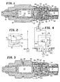
- valve 10 is depicted having primary port 12 which is connected to secondary port 14 when piston head 16 is displaced.
- Valve 10 has a main housing 18 which includes control spring chamber 20 in which control spring 22 is disposed.
- Spring guides 24 and 26 are positioned at the ends of control spring 22.
- Spring guide 24 has a rounded end, which may be a press fitted ball 28, which bears against a depression in piston driver 30.
- Spring guide 26 has a similar rounded end 32 which bears against a depression in spring chamber closure 34.
- Spring chamber closure 34 is made longitudinally adjustable by having a threaded portion 36 which can be screwed in and out to change the spring force.
- a T-shaped slot extends through piston driver 30 to receive and lock for longitudinal movement piston head extension 38.
- Piston head 16 has a radially outwardly extending portion with a longitudinal annular extension 40.
- the inner edge of annular extension 40 forms a seal against valve seat 42.
- Passage 44 leads from secondary port 14 to chamber 46 so that the pressure in chamber 46 is the same as secondary port pressure.
- diameter 47 of piston head 16 is made the same as the seal diameter. This balance of areas makes the valve insensitive to secondary port pressure.
- Direct-acting sequence valve 10 includes a spring force reduction chamber 48 which is connected by passage 50 through piston head 16 to primary port 12.
- the piston face area exposed to primary port hydraulic pressure creates an opening force which is partially offset by an area in spring force reduction chamber 48 which resists the opening force.
- the area which is not offset is represented by the minor diameter, indicated by arrows, of piston shaft 52.
- Low friction two way seals which include an O-ring and an annular ring of a low friction material such as Teflon are used as appropriate to provide a seal at sliding surfaces.
- valve seat 42 is slideably mounted in valve extension 54 and is normally held by spring 56 assisted by pressure at the primary port in sealing position.
- Spring 56 is selected to have a low spring constant so as to permit valve seat 42 to move open when pressure at secondary port 14 exceeds that at primary port 12 by the spring force plus the net force exerted on the seat by primary port pressure by a small, nominal amount.
- the primary port hydraulic fluid can enter the chamber which contains spring 56. This pressure acts on the seat wall surface in this chamber to produce a force which is only partially offset by pressure at the opposite end of the seat acting on a smaller wall area.
- a third port is included which is defined by annular external groove 58. This third port is a drain to reservoir. This provides a necessary low, reference pressure so that valve opening pressure will be predictable.
- Passage 60 connects groove 58 to gap 62 between piston driver 30 and fixed partition 64. Consequently, primary port pressure acting on an area defined by the diameter of piston shaft 52 produces force which is opposed only by control spring 22.
- Direct-acting sequence valve also includes passage 66 between spring chamber 20 and third reservoir port 58.
- the passages to the third port are large enough to provide free drainage for hydraulic fluid to reservoir so as not to restrict valve opening.
- pump 68 supplies hydraulic fluid at the desired pressure to primary port 12 of direct-acting sequence valve 10.
- Check valve 70 represents the free reverse flow characteristic from secondary port 14 to primary port 12.
- Broken line 72 represents the fact that primary port pressure opposes spring force to open the valve.
- Broken line 74 indicates that only spring force opposes opening force - as indicated above, both the spring chamber and the gap 62 are connected to reservoir.
- a sequence of operations controlled by valves can be ordered by connecting the valves in parallel to the line supplied by pump 68 and assigning different set pressures to the valves. In this manner, as the pressure in the line increases, the valve with the lowest set pressure will open first. This minimum pressure always is assured in the line supplied by pump 68.
- a pilot pressure port is provided in this valve using port 58 and passage 60 to introduce hydraulic fluid to act as a pilot pressure.
- This pressure is applied in gap 62 and acts on the large area of piston driver 30 in this gap as well as the small area of piston shaft 52 resulting in a net force to aid in opening the valve.
- Seals 80 and 82 serve to prevent loss of this hydraulic pressure by leakage into spring chamber 20.
- Spring chamber 20 is provided with vent passage 86 which has O-ring 88 covering the opening to prevent contaminents from entering the spring chamber. Vent passage 86 is designed to vent to atmosphere.
- An alternate embodiment substitutes fourth port 89 (shown in broken lines) which is piped directly to reservoir for vent passage 86.
- pilot pressure When directional control valve 110 is shifted to the LOWER position, pump 112 oil flow is directed to the piston rod side of cylinder 114 and also to pilot port 60 of counterbalance valve 76. The net force exerted by this pilot pressure assists the load pressure in opening the valve. Since some pressure is always required at the pilot port to keep the valve open, the load can never "run away” from the pump. Flow from the cylinder is restrained, preventing cavitation which would occur if the load ran ahead of the pump. When the directional control valve is again centered, pilot pressure goes to zero and the counterbalance valve closes, smoothly decelerating and locking the load.
Landscapes
- Engineering & Computer Science (AREA)
- General Engineering & Computer Science (AREA)
- Mechanical Engineering (AREA)
- Safety Valves (AREA)
Claims (11)
- Clapet ou valve de régulation de pression à pression absolue de consigne, comprenant : un corps de valve disposé longitudinalement (18); un siège de valve (42) définissant un orifice primaire (12) à une extrémité dudit corps; une chambre de ressort de régulation (20) dans ledit corps; un ressort de régulation (22) dans ladite chambre de ressort de régulation; une fermeture de chambre de ressort, réglable longitudinalement (34) à l'autre extrémité dudit corps, fermant une extrémité de ladite chambre de ressort de régulation; un ensemble de piston (30, 52, 16) monté de manière à effectuer un déplacement longitudinal dans ledit corps; ledit ensemble de piston comprenant des moyens d'entraînement de piston (30), une tête de piston (16) et une tige de piston (52); lesdits moyens d'entraînement de piston étant disposés à l'autre extrémité de ladite chambre de ressort de régulation; ladite tête de piston comprenant un premier diamètre et une extension annulaire longitudinale (40); ladite extension annulaire longitudinale de ladite tête de piston comprenant un bord formant un joint avec ledit siège de valve lorsque ladite valve est fermée; ledit joint ayant un diamètre égal audit premier diamètre de ladite tête de piston; un orifice secondaire (14) traversant ledit corps, adjacent audit siège de valve, de manière à ménager un passage à partir dudit orifice primaire jusqu'audit orifice secondaire lorsque ladite valve est ouverte; ladite tige de piston reliant lesdits moyens d'entraînement de piston et ladite tête de piston; une chambre annulaire de réduction de force de tension du ressort (48) entre lesdits moyens d'entraînement de piston et ladite tête de piston; et un passage (47) entre ladite chambre de réduction de force de tension et ledit orifice primaire, de manière que le fluide hydraulique à la pression de l'orifice primaire puisse pénétrer dans ladite chambre de réduction de force de tension de ressort et absorber partiellement la force exercée par le fluide hydraulique sur ledit orifice primaire, caractérisée en ce que ledit bord de ladite extension annulaire longitudinale (40) est un bord intérieur formant ledit joint avec ledit siège de valve (42) lorsque ladite valve est fermée; ladite extension annulaire longitudinale (40) de ladite tête de piston (16) comprend une face annulaire s'étendant à partir dudit bord intérieur exposé au fluide hydraulique dans ledit orifice secondaire; ledit siège de valve est monté pour effectuer un déplacement longitudinal dans ledit corps de valve; qu'un ressort sollicite ledit siège en position fermée; et que la pression hydraulique dans ledit orifice secondaire déplace ledit siège de valve de sa position fermée, de manière que ladite valve possède une caractéristique d'inversion de courant libre.
- Valve de régulation de pression selon la revendication 1, dans laquelle : la tête de piston comprend une surface disposée en opposition par rapport à la face annulaire et de dimension égale à celle de ladite face annulaire, également exposée au fluide hydraulique à partir dudit orifice secondaire, de manière que les forces exercées par le fluide hydraulique sur ledit orifice secondaire soient égales et opposées.
- Valve de régulation de pression selon la revendication 1, comprenant en outre : une cloison fixe, étanche aux fuites (64) entre lesdits moyens d'entraînement de piston (30) et ladite tête de piston (16) entourant ladite tige de piston (52); un intervalle (62) entre ladite cloison (64) et lesdits moyens d'entraînement de piston (30); et un troisième orifice (58, 60), relié audit intervalle.
- Valve de régulation de pression selon la revendication 3, comprenant en outre : un passage (66) entre ladite chambre de ressort de régulation et ledit troisième orifice.
- Valve de régulation de pression selon la revendication 3, comprenant en outre : un passage traversant ledit corps à partir de ladite chambre de commande de ressort; et ladite fermeture de chambre de ressort réglable (34) fermant ledit passage traversant ledit corps de façon réglable.
- Valve de régulation de pression comprenant : un corps de valve s'étendant longitudinalement; un ensemble de piston (30, 52, 16) monté de manière à effectuer un déplacement longitudinal dans ledit corps; ledit ensemble de piston comprenant une tête de piston (16) à une extrémité, des moyens d'entraînement de piston (30) à l'autre extrémité et une tige de piston (52) reliant ladite tête de piston et lesdits moyens d'entraînement de piston; un siège de valve (42) monté dans ledit corps, adjacent à ladite tête de piston; ledit siège de valve définissant un orifice primaire (12) de ladite valve à une extrémité dudit corps de valve; une cloison fixe (64) entre ladite tête de piston et lesdits moyens d'entraînement de piston, entourant ladite tige de piston; une chambre de réduction de tension de ressort (48) entre ladite tête de piston et ladite cloison fixe; un passage (47) entre ladite chambre de réduction de tension de ressort et ledit orifice primaire, de manière que le fluide hydraulique à la pression de l'orifice primaire puisse entrer dans ladite chambre de réduction de tension de ressort et compenser partiellement la force hydraulique sur ladite tête de piston; une chambre de ressort de régulation (20) dans ledit corps; un ressort de réglage (22) dans ladite chambre de ressort de régulation; une fermeture de chambre de tension de ressort réglable longitudinalement (34) à une extrémité dudit ressort de régulation; lesdits moyens d'entraînement de piston à l'autre extrémité dudit ressort de commande; et un orifice secondaire (14) dans ledit corps, adjacent audit siège de valve, de manière à ménager un passage à partir dudit orifice primaire jusqu'audit orifice secondaire lorsque ladite valve est ouverte; caractérisé en ce qu'un orifice de détente (86) relié à ladite chambre de ressort, de manière que la pression hydraulique dans ladite chambre de ressort soit négligeable; que ledit siège de valve est monté pour effectuer un déplacement longitudinal dans une extension de valve; qu'un ressort sollicite ledit siège de valve en position fermée; et que la pression hydraulique dudit orifice secondaire déplace ledit siège de valve de sa position fermée; de manière que ladite valve possède une caractéristique d'inversion de courant libre.
- Valve de régulation de pression selon la revendication 6, dans laquelle : ladite tête de piston comprend une première surface exposée à la pression dans ledit orifice secondaire, tendant à provoquer l'ouverture de ladite valve; ladite tête de piston comprend une seconde surface égale, exposée à la pression dans ledit orifice secondaire, tendant à provoquer la fermeture de ladite valve, de manière que ladite valve soit insensible à la pression de l'orifice secondaire.
- Valve de régulation de pression selon la revendication 7, comprenant en outre : un troisième orifice (58, 60); un intervalle (62) entre ladite cloison fixe (64) et lesdits moyens d'entraînement de piston (30); et un passage reliant ledit intervalle et ledit troisième orifice.
- Valve de régulation de pression selon la revendication 7, comprenant en outre : un passage (66) entre ladite chambre de ressort de régulation et ledit troisième orifice.
- Valve de commande de pression selon la revendication 8, comprenant en outre : un passage traversant ledit corps de valve à partir de ladite chambre de ressort de régulation; et ladite fermeture de chambre de ressort de régulation (34) fermant de façon réglable ledit passage à travers ledit corps.
- Valve de régulation de pression selon la revendication 4 ou 5 ou 8, comprenant en outre : un premier guide de ressort (26) disposé entre ledit ressort de réglage (22) et ladite fermeture de chambre de ressort (34); un deuxième guide de ressort (24) disposé entre ledit ressort de réglage et lesdits moyens d'entraînement de piston (30); lesdits premier et deuxième guides de ressort étant pourvus d'une surface arrondie venant en butée, respectivement, contre ladite fermeture de chambre de ressort et lesdits moyens d'entraînement de piston.
Applications Claiming Priority (2)
| Application Number | Priority Date | Filing Date | Title |
|---|---|---|---|
| US07/266,168 US4834135A (en) | 1988-11-01 | 1988-11-01 | Pressure control valve |
| US266168 | 1988-11-01 |
Publications (2)
| Publication Number | Publication Date |
|---|---|
| EP0367461A1 EP0367461A1 (fr) | 1990-05-09 |
| EP0367461B1 true EP0367461B1 (fr) | 1994-03-02 |
Family
ID=23013465
Family Applications (1)
| Application Number | Title | Priority Date | Filing Date |
|---|---|---|---|
| EP89310836A Expired - Lifetime EP0367461B1 (fr) | 1988-11-01 | 1989-10-20 | Clapet de contrôle de pression |
Country Status (3)
| Country | Link |
|---|---|
| US (1) | US4834135A (fr) |
| EP (1) | EP0367461B1 (fr) |
| DE (1) | DE68913425T2 (fr) |
Families Citing this family (9)
| Publication number | Priority date | Publication date | Assignee | Title |
|---|---|---|---|---|
| US5275086A (en) * | 1992-08-27 | 1994-01-04 | Unlimited Solutions, Inc. | Fluid actuator with internal pressure relief valve |
| EP1511954B1 (fr) | 2002-06-12 | 2006-01-11 | FSP Fluid Systems Partners Holding AG | Soupape a visser |
| US7467642B2 (en) * | 2005-03-11 | 2008-12-23 | Sun Hydraulics Corp. | Soft ventable relief valve |
| US9091355B2 (en) | 2013-03-15 | 2015-07-28 | David Albrecht | Main stage in-line pressure control cartridge with optional reverse flow function |
| US9850919B2 (en) | 2014-09-16 | 2017-12-26 | Sun Hydraulics Corporation | Counterbalance valve with dual or triple pilot ratio |
| US11353127B2 (en) * | 2020-04-28 | 2022-06-07 | Sun Hydraulics, Llc | Vented counterbalance valve with two setting springs in parallel |
| US11384857B1 (en) * | 2021-07-02 | 2022-07-12 | Sun Hydraulics, Llc | Bidirectional pressure relief valve |
| US12271212B2 (en) | 2023-07-10 | 2025-04-08 | Sun Hydraulics, Llc | Counterbalance valve with enhanced pressure sensing features |
| US20250347174A1 (en) * | 2024-05-13 | 2025-11-13 | Caterpillar Inc. | System for moving mast of drilling machine |
Family Cites Families (9)
| Publication number | Priority date | Publication date | Assignee | Title |
|---|---|---|---|---|
| GB649014A (en) * | 1948-07-07 | 1951-01-17 | Uni Gun Lubricating Equipment | Improvements in or relating to pressure relief valves |
| DE1254925B (de) * | 1965-06-12 | 1967-11-23 | Voith Gmbh J M | Federbelastetes UEberdruckventil, insbesondere fuer Druckraeume |
| DE1800524A1 (de) * | 1968-10-02 | 1970-05-14 | Voith Gmbh J M | Federbelastetes UEberdruckventil,insbesondere fuer Druckraeume |
| DE2537715C3 (de) * | 1975-08-23 | 1980-11-06 | Saarbergwerke Ag, 6600 Saarbruecken | Druckminderventilanordnung und -ausbildung für die Verbindung der beiden Druckräume eines zweistufigen teleskopischen Grubenstempels |
| US4428396A (en) * | 1978-07-19 | 1984-01-31 | City Tank Corporation | Adjustable valve assembly |
| US4591314A (en) * | 1984-07-09 | 1986-05-27 | Sundstrand Corporation | Hydraulic power supply system utilizing a solid propellant gas generator |
| EP0211074B1 (fr) * | 1985-02-08 | 1992-04-29 | DiBARTOLO, Ernest, A. | Clapet de detente pour piston differentiel, a action directe |
| US4597410A (en) * | 1985-08-30 | 1986-07-01 | Husco International | Cross line relief valve mechanism |
| DE3742722A1 (de) * | 1987-12-17 | 1989-07-06 | Babcock Werke Ag | Direkt wirkendes sicherheitsventil |
-
1988
- 1988-11-01 US US07/266,168 patent/US4834135A/en not_active Expired - Lifetime
-
1989
- 1989-10-20 DE DE68913425T patent/DE68913425T2/de not_active Expired - Fee Related
- 1989-10-20 EP EP89310836A patent/EP0367461B1/fr not_active Expired - Lifetime
Also Published As
| Publication number | Publication date |
|---|---|
| DE68913425D1 (de) | 1994-04-07 |
| DE68913425T2 (de) | 1994-08-25 |
| EP0367461A1 (fr) | 1990-05-09 |
| US4834135A (en) | 1989-05-30 |
Similar Documents
| Publication | Publication Date | Title |
|---|---|---|
| US5873561A (en) | Two-port cartridge seat valve | |
| US5036877A (en) | Pilot controlled pressure relief valve | |
| US4836240A (en) | Pilot-assisted pressure relief valve | |
| WO2002012732A3 (fr) | Systeme de vanne de regulation hydraulique a regulation de debit par compensation de pression | |
| US3583431A (en) | Pressure relief valve | |
| EP0367461B1 (fr) | Clapet de contrôle de pression | |
| CA2444454C (fr) | Clapet anti-retour commande par pilote avec compensation de pression | |
| US4649957A (en) | Fluid assisted spring return for pilot operated, spool valve | |
| US4997159A (en) | Logic valve | |
| US6095177A (en) | Precontrolled 3-way pressure control valve | |
| EP1255044B1 (fr) | Dispositif de contrôle de pression variable | |
| US4795129A (en) | Normally closed fluid switching logic element | |
| GB1574649A (en) | Pressure limiting and make-up valve | |
| CN101652735B (zh) | 压力阀 | |
| US2498542A (en) | Relief valve for power transmissions | |
| SE442765B (sv) | Lasthallningsventil | |
| AU2010203119B2 (en) | Hydraulic valves | |
| US5080129A (en) | Pilot operated pressure reducing valve | |
| US3272227A (en) | Pilot operated pressure regulator | |
| US20080000534A1 (en) | Cartridge valve assembly | |
| JP3175066B2 (ja) | パイロット操作形リリーフ弁 | |
| GB2197433A (en) | Fluid control valves | |
| JP2912620B2 (ja) | 切換弁 | |
| JPS63145804A (ja) | パイロツト作動式開閉弁 | |
| CN109555745B (zh) | 压力控制阀 |
Legal Events
| Date | Code | Title | Description |
|---|---|---|---|
| PUAI | Public reference made under article 153(3) epc to a published international application that has entered the european phase |
Free format text: ORIGINAL CODE: 0009012 |
|
| AK | Designated contracting states |
Kind code of ref document: A1 Designated state(s): DE FR GB IT SE |
|
| 17P | Request for examination filed |
Effective date: 19901015 |
|
| 17Q | First examination report despatched |
Effective date: 19920423 |
|
| GRAA | (expected) grant |
Free format text: ORIGINAL CODE: 0009210 |
|
| AK | Designated contracting states |
Kind code of ref document: B1 Designated state(s): DE FR GB IT SE |
|
| PG25 | Lapsed in a contracting state [announced via postgrant information from national office to epo] |
Ref country code: IT Free format text: LAPSE BECAUSE OF FAILURE TO SUBMIT A TRANSLATION OF THE DESCRIPTION OR TO PAY THE FEE WITHIN THE PRE;WARNING: LAPSES OF ITALIAN PATENTS WITH EFFECTIVE DATE BEFORE 2007 MAY HAVE OCCURRED AT ANY TIME BEFORE 2007. THE CORRECT EFFECTIVE DATE MAY BE DIFFERENT FROM THE ONE RECORDED.SCRIBED TIME-LIMIT Effective date: 19940302 Ref country code: SE Free format text: THE PATENT HAS BEEN ANNULLED BY A DECISION OF A NATIONAL AUTHORITY Effective date: 19940302 Ref country code: FR Free format text: THE PATENT HAS BEEN ANNULLED BY A DECISION OF A NATIONAL AUTHORITY Effective date: 19940302 |
|
| REF | Corresponds to: |
Ref document number: 68913425 Country of ref document: DE Date of ref document: 19940407 |
|
| EN | Fr: translation not filed | ||
| PLBE | No opposition filed within time limit |
Free format text: ORIGINAL CODE: 0009261 |
|
| STAA | Information on the status of an ep patent application or granted ep patent |
Free format text: STATUS: NO OPPOSITION FILED WITHIN TIME LIMIT |
|
| 26N | No opposition filed | ||
| REG | Reference to a national code |
Ref country code: GB Ref legal event code: IF02 |
|
| PGFP | Annual fee paid to national office [announced via postgrant information from national office to epo] |
Ref country code: GB Payment date: 20031016 Year of fee payment: 15 |
|
| PGFP | Annual fee paid to national office [announced via postgrant information from national office to epo] |
Ref country code: DE Payment date: 20031030 Year of fee payment: 15 |
|
| PG25 | Lapsed in a contracting state [announced via postgrant information from national office to epo] |
Ref country code: GB Free format text: LAPSE BECAUSE OF NON-PAYMENT OF DUE FEES Effective date: 20041020 |
|
| PG25 | Lapsed in a contracting state [announced via postgrant information from national office to epo] |
Ref country code: DE Free format text: LAPSE BECAUSE OF NON-PAYMENT OF DUE FEES Effective date: 20050503 |
|
| GBPC | Gb: european patent ceased through non-payment of renewal fee |
Effective date: 20041020 |