EP0367495B1 - Öl- und Gasexplorationsverfahren und -anordnung - Google Patents
Öl- und Gasexplorationsverfahren und -anordnung Download PDFInfo
- Publication number
- EP0367495B1 EP0367495B1 EP89311046A EP89311046A EP0367495B1 EP 0367495 B1 EP0367495 B1 EP 0367495B1 EP 89311046 A EP89311046 A EP 89311046A EP 89311046 A EP89311046 A EP 89311046A EP 0367495 B1 EP0367495 B1 EP 0367495B1
- Authority
- EP
- European Patent Office
- Prior art keywords
- sample
- measurement
- station
- code
- physical properties
- Prior art date
- Legal status (The legal status is an assumption and is not a legal conclusion. Google has not performed a legal analysis and makes no representation as to the accuracy of the status listed.)
- Expired - Lifetime
Links
- 238000000034 method Methods 0.000 title claims description 42
- 238000005259 measurement Methods 0.000 claims description 106
- 230000000704 physical effect Effects 0.000 claims description 88
- 230000015572 biosynthetic process Effects 0.000 claims description 85
- 238000005755 formation reaction Methods 0.000 claims description 85
- 238000012545 processing Methods 0.000 claims description 22
- 238000011065 in-situ storage Methods 0.000 claims description 14
- 238000009499 grossing Methods 0.000 claims description 4
- 230000000977 initiatory effect Effects 0.000 claims description 4
- 238000002372 labelling Methods 0.000 claims description 4
- 239000007789 gas Substances 0.000 description 14
- 229920006395 saturated elastomer Polymers 0.000 description 11
- 239000011435 rock Substances 0.000 description 9
- 238000005553 drilling Methods 0.000 description 8
- 239000012530 fluid Substances 0.000 description 8
- 230000006870 function Effects 0.000 description 7
- 230000008569 process Effects 0.000 description 7
- 238000004458 analytical method Methods 0.000 description 6
- 238000005341 cation exchange Methods 0.000 description 5
- 230000005251 gamma ray Effects 0.000 description 5
- 238000005070 sampling Methods 0.000 description 5
- 230000005855 radiation Effects 0.000 description 3
- 238000013179 statistical model Methods 0.000 description 3
- 238000003860 storage Methods 0.000 description 3
- 230000002596 correlated effect Effects 0.000 description 2
- 238000006073 displacement reaction Methods 0.000 description 2
- 230000005484 gravity Effects 0.000 description 2
- 238000005404 magnetometry Methods 0.000 description 2
- 239000011148 porous material Substances 0.000 description 2
- 230000004044 response Effects 0.000 description 2
- ZSLUVFAKFWKJRC-IGMARMGPSA-N 232Th Chemical compound [232Th] ZSLUVFAKFWKJRC-IGMARMGPSA-N 0.000 description 1
- 229920002799 BoPET Polymers 0.000 description 1
- 239000004698 Polyethylene Substances 0.000 description 1
- 235000015076 Shorea robusta Nutrition 0.000 description 1
- 244000166071 Shorea robusta Species 0.000 description 1
- 229910052776 Thorium Inorganic materials 0.000 description 1
- 229910052770 Uranium Inorganic materials 0.000 description 1
- 230000002411 adverse Effects 0.000 description 1
- 230000000712 assembly Effects 0.000 description 1
- 238000000429 assembly Methods 0.000 description 1
- 230000005540 biological transmission Effects 0.000 description 1
- 238000004891 communication Methods 0.000 description 1
- 230000001276 controlling effect Effects 0.000 description 1
- 238000010586 diagram Methods 0.000 description 1
- 230000000694 effects Effects 0.000 description 1
- 238000011156 evaluation Methods 0.000 description 1
- 239000001307 helium Substances 0.000 description 1
- 229910052734 helium Inorganic materials 0.000 description 1
- SWQJXJOGLNCZEY-UHFFFAOYSA-N helium atom Chemical compound [He] SWQJXJOGLNCZEY-UHFFFAOYSA-N 0.000 description 1
- 238000003384 imaging method Methods 0.000 description 1
- 230000010354 integration Effects 0.000 description 1
- 238000009533 lab test Methods 0.000 description 1
- 230000007246 mechanism Effects 0.000 description 1
- 230000005055 memory storage Effects 0.000 description 1
- 238000012986 modification Methods 0.000 description 1
- 230000004048 modification Effects 0.000 description 1
- 230000010287 polarization Effects 0.000 description 1
- -1 polyethylene Polymers 0.000 description 1
- 229920000573 polyethylene Polymers 0.000 description 1
- ZLMJMSJWJFRBEC-OUBTZVSYSA-N potassium-40 Chemical compound [40K] ZLMJMSJWJFRBEC-OUBTZVSYSA-N 0.000 description 1
- 230000003068 static effect Effects 0.000 description 1
- 238000012360 testing method Methods 0.000 description 1
- JFALSRSLKYAFGM-UHFFFAOYSA-N uranium(0) Chemical compound [U] JFALSRSLKYAFGM-UHFFFAOYSA-N 0.000 description 1
- XLYOFNOQVPJJNP-UHFFFAOYSA-N water Substances O XLYOFNOQVPJJNP-UHFFFAOYSA-N 0.000 description 1
- 238000005303 weighing Methods 0.000 description 1
Images



Classifications
-
- G—PHYSICS
- G01—MEASURING; TESTING
- G01V—GEOPHYSICS; GRAVITATIONAL MEASUREMENTS; DETECTING MASSES OR OBJECTS; TAGS
- G01V11/00—Prospecting or detecting by methods combining techniques covered by two or more of main groups G01V1/00 - G01V9/00
Definitions
- the present invention relates generally to apparatus for and a method of processing a plurality of samples of the earth's subterranean formations, and hence is concerned with geophysical exploration.
- the invention relates more particularly to a method of and apparatus for obtaining selected physical properties from samples of the earth's subterranean formations surrounding a wellbore and for obtaining inverse logs of the selected physical properties along the length of the wellbore for evaluating the oil and gas bearing potential of the earth's subterranean formations.
- seismic exploration comprises imparting seismic energy into the earth and recording the earth's response thereto.
- the earth response can include both refracted and reflected seismic energy. As the seismic energy propagates through the earth, it is controlled by the physical properties of the rocks and the fluids contained therein.
- seismic exploration techniques merely provide a measure of the time it takes the seismic energy to traverse some path. In fact, it is often times impossible to precisely ascertain the path taken by the seismic energy. In view of such uncertainties, how is it that explorationists are able to estimate formation lithology, fluid content or even simple, reconstruct formation geometries through which the seismic energy propagates with only a measure of time? Quite simply, the answer is explorationists cannot without the aid of additional information such as estimates of the velocities of propagation of seismic energy in rock and rock density as well as other rock and fluid physical properties. Methods for estimating the velocity of propagation and a density as a function of depth are generally known to those skilled in the art; however, velocity estimations are the weakest element in the inversion of seismic time data.
- wells which have been drilled based on geophysical survey data are logged using one or more of the well logging techniques such as acoustic logging, resistivity logging, neutron logging, etc.
- Results of such well logging techniques can provide the explorationist with selected physical properties generally over regions of interest along the wellbore length.
- explorationists are able to obtain better estimates of the formation physical properties for evaluating geophysical survey data.
- it must be recognized that such well logging techniques still only provide an indirect measure of the formation physical properties of interest and are generally limited to only selected regions of interest within a wellbore.
- core samples are obtained from limited regions of interest within a wellbore for transport to a central laboratory so that physical properties of the formations adjacent the borehole, such as fluid content of the sample, (U.S. Patent 2,458,093 M. Muskat, et al., January 4, 1949), oil content of the sample (U.S. Patent 2,531,083, A. L. Smith, November 21, 1950), and electrical resistivity of the sample (U.S. Patent 2,613,250, H. L. Bilhartz, et al., October 7, 1952), can be obtained.
- such core samples generally represent only a small fraction of the formational lithologies traversed by the wellbore along its length.
- the delay associated with transporting the samples to the central laboratory can preclude the measurement of properties of certain friable lithologies or result in seriously degraded measurements of certain properties.
- chips which have broken away from the subsurface formations can be captured from the drilling fluid at the surface for analysis.
- explorationists have identified the lithologies of the subsurface formations from such chips.
- determining the exact depth in the wellbore from which the chips originated is generally not possible due to the very nature of their transport to the surface.
- core samples and chip samples fail to provide either a regular sampling of borehole formation lithologies along the length of the wellbore or fail to accurately determine the depth of origin of such samples so that logs of formation characteristics, as a function of depth over generally the entire wellbore length, cannot be produced.
- the very nature of the chip samples can often times preclude measuring certain formation characteristics (for example, measurement of rock velocity or compressive strength).
- the cation exchange capacities thus are developed then correlated with selected parameters, provided by the gamma ray spectrometer to establish functional relationships. Cation exchange capacities of formations in subsequent boreholes within the region are then determined in situ by use of the natural gamma ray spectrometer and these established relationships.
- the method comprises deriving a plurality of measurements related functionally to a respective plurality of different earth formation characteristics along borehole sections traversing earth formations in a field; forming first data sets, each comprising a defined combination of said measurements; combining at least a defined portion of said first data sets to form a statistical model of the traversed earth formations; and combining second data sets derived from a borehole in the same field with said statistical model to determine what modification of the second data sets may be necessary to bring them into a defined statistical conformity with the statistical model.
- the present invention seeks to provide a novel method of and apparatus for obtaining selected physical properties from samples of the earth's subterranean formations surrounding a wellbore and developing inverse logs of the selected physical properties along the length of the wellbore.
- Explorationists can employ such inverse logs of the selected physical properties to perform basin analysis whereby the physical properties obtained at one or more wellbores can be used to calibrate geophysical survey data at each wellbore location and then extrapolate such physical properties to other locations in the basin with the geophysical survey data so as to evaluate the oil and gas bearing potential of the earth's subterranean formations.
- apparatus for processing a plurality of samples of the earth's subterranean formations so as to obtain a plurality of physical properties for each sample representative of their in-situ condition comprising (a) a unique machine readable sample code label for each sample; (b) a plurality of measurement stations for measuring a plurality of selected physical properties, wherein each measurement station is adapted to measure at least one physical property for each sample and wherein there is a unique machine readable station code for each measurement station; (c) reader means for reading the sample codes and station codes for a sample at a selected measurement station; and (d) central processing means (CPU) for initiating the measurement of at least one physical property of a sample at a selected measurement station upon receiving a station code and a sample code from the reader means and for storing said physical property measurement.
- CPU central processing means
- the present invention provides a method of processing a plurality of samples of the earth's subterranean formations at a plurality of measurement stations so as to obtain a plurality of physical properties for each sample representative of their in-situ condition, comprising the steps of: (a) labelling each sample with a unique machine readable sample code; (b) assigning each measurement station a unique machine readable station code; (c) machine reading the sample code and station code of a sample at a selected measurement station into a central processing unit (CPU); and (d) arranging the central processing unit to be responsive to receipt of the sample code and the station code, to initiate a measurement of at least one physical property of the sample at the selected measurement station, and to store the measurement of the physical property.
- CPU central processing unit
- discrete samples can be obtained at selected intervals along the length of a wellbore so as to be representative of the formation lithologies traversed by the wellbore along its length.
- the discrete samples can then be processed at the wellsite with a transportable laboratory so as to obtain measures of a plurality of selected physical properties of the subterranean formations representative of their in-situ condition.
- An inverse log of each physical property as a function of depth can be prepared with which explorationists can evaluate geophysical survey data for oil and gas potential.
- measures of the subterranean formation's compressional wave velocity, shear wave velocity, grain density, saturated density, dry density, magnetic susceptibility, compressive strength, and static elastic moduli can be determined from which one can also calculate the formation's acoustic impedance and porosity.
- Inverse logs of one or more of the physical properties can be used to perform basin analyses.
- the physical properties of each inverse log can be used to calibrate geophysical survey data of the basin at one or more wellbore sites within the basin from which the inverse logs were obtained. Having thus calibrated the geophysical survey data, explorationists can then extrapolate the physical properties to other locations in the basin remote to the wellbore site with the geophysical survey data to evaluate the oil and gas potential of the earth's subterranean formations at such remote locations.
- a transportable laboratory which is especially adapted for processing, at a wellsite, large numbers of discrete samples obtained along the length of a wellbore in a minimum amount of time so as to obtain measures of the formations physical properties which more properly reflect their in-situ condition.
- Timely measurement of the physical properties of certain friable lithologies is essential if physical properties are to be obtained at all.
- the in-situ measures of certain physical properties can be seriously degraded by a delay in measurement e.g., seismic energy velocities of propagation in the rock, and porosity.
- such properties have been found to vary over a wide range of values simply due to a delay in the time of their measurement.
- the transportable laboratory comprises a plurality of highly automated measurement stations each connected to a central processing unit (CPU).
- CPU central processing unit
- reader means can be provided for reading the sample code of each sample and the station code of a selected measurement station into the CPU.
- the CPU Upon receipt of valid sample and station codes, the CPU initiates the measurement of the sample at the selected measurement station and stores the measurements in a data file associated with the unique sample code.
- the CPU can also calculate additional physical properties from selected measured physical properties.
- the transportable laboratory becomes in effect a "paperless" laboratory since manual recordation of a sample's identity and its measured and calculated physical properties has been eliminated.
- the paperless laboratory greatly reduces errors generally associated with manually recording such information.
- the CPU can initiate a prescribed sequence of measurements at a given measurement station as well as collect, collate and evaluate the physical properties measured to provide inverse well logs of the measured properties as a function of depth. Additionally, the CPU can calculate additional physical properties from the physical properties measured as well as reinterpret geophysical survey data and models at a remote site.
- explorationists often times employ the time it takes seismic energy to travel from the earth's surface to a reflecting horizon and back again to infer structure, lithology, porosity fluid content as well as the path traversed by the seismic energy.
- magnetic surveys can provide estimates of formation structure.
- geophysical and geological survey techniques do not generally directly measure the properties of interest, but rather simply provide indirect measures of other characteristics of the formation from which it is possible for the explorationist to estimate the physical properties of interest.
- well logging techniques such as sonic logging, electric resistivity logging, gamma ray logging, gravity logging, neutron logging, etc.
- additional sources of error such as borehole rugosity, mudcaking, varying borehole dimensions, variation of and borehole fluids
- wellbores have been cored to provide a few samples of selected formations over limited intervals adjacent the wellbore from which direct measures can be obtained. Generally, such samples are obtained at a wellsite and then transported to a central facility for measurement some time thereafter.
- core samples can be obtained over substantially the entire length of a wellbore; however, an important aspect of the present invention is that discrete samples of the earth's formations surrounding a wellbore need only be taken at selected intervals along the length of the wellbore.
- One criteria for establishing the sampling intervals is that discrete samples generally be obtained for every formation lithology traversed by the wellbore along its length. Since the physical properties of the formations surrounding the wellbore can also be used to evaluate and calibrate geophysical survey data (e.g., seismic survey data), the minimum resolution interval of the geophysical survey data being evaluated establishes another criteria for the sampling interval.
- seismic data has the finest resolution interval of any geophysical survey technique (approximately 30 m (100 ft)).
- a sampling interval of one sample every 3 m (10 ft) adequately addresses the criteria of lithology changes as well as the geophysical survey minimum resolution interval criteria so as to address the problems of heterogeneous rather than homogeneous earth formations so that the physical properties of the samples can be correlated with geophysical survey data without introducing sampling bias.
- a transportable laboratory is provided so as to process samples obtained from the earth's formations surrounding a wellbore along its length. Since timely measurement of certain physical properties and of certain lithologies can be important, the transportable laboratory is preferably configured for field operation in the vicinity of the wellbore. Generally, the transportable laboratory comprises a plurality of measurement stations, each adapted to measure at least one physical property of each sample. Additionally, the transportable laboratory includes a central processing unit for identifying samples, initiating measurements on the samples at selected measurement stations, and storing the measured physical properties in a sample data file.
- Every sample which enters the transportable laboratory A is given a unique machine readable sample code (which includes a well identifier, date and depth).
- sample codes are included on a label adapted to be mounted on each sample.
- Every measurement station is assigned a unique machine readable station code.
- the sample codes and station codes are bar codes which can be read by a laser bar code reader into a central processing unit (CPU).
- CPU central processing unit
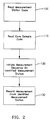
- the machine readable station code (preferably a bar code) assigned to a selected measurement station is read into the CPU using a laser bar code reader 70 at step 100.
- the sample to be measured at the selected measurement station then has its unique machine readable sample code (preferably a bar code) read into the CPU with the laser bar code reader 70 at step 110. If the station code and the sample code are both valid codes, the CPU directs the selected measurement station at Step 120 to initiate a sequence of measurements unique to the selected measurement station and the set of measurements obtained are then stored in the CPU at step 130 in a sample data file associated with the sample's unique sample code.
- the transportable laboratory A comprises a plurality of uniquely identified measurement stations connected to a central processing unit (CPU) such as a Hewlett-Packard 9000 series 500 computer and a laser bar code reader 70 as manufactured by Intermec.
- the CPU also includes a mass storage system (not shown) for collecting and storing the physical properties obtained from the various samples which are processed by the transportable laboratory A.
- the transportable laboratory A includes an electronic dimension jig 10 for digitally measuring sample lengths and diameters.
- the dimensioning jig 10 includes pairs of opposed linear voltage displacement transducers (LVDT) adapted to measure axial and lateral dimensions of each sample.
- the transportable laboratory A also includes an electronic balance 20 adapted to measure the weight of each sample.
- an electronically driven pycnometer 30 is provided to measure grain density of each sample; a triaxial loading apparatus 40 is provided to obtain measures of each sample's compressive strength, as well as provide an input for calculating Young's modulus and Poisson's ratio for each sample; an electronic magnetic susceptibility meter 50 is provided to obtain a measure of the magnetic susceptibility for a given weight of sample; and a pair of electronically driven pressure velocity cells 60 are provided to measure the velocities of propagation of compressional (P), horizontal shear (SH), and vertical shear (SV) waves in each sample as a function of pressure.
- P compressional
- SH horizontal shear
- SV vertical shear
- a laser bar code reader 70 is provided to read both the unique sample codes assigned to each sample and the unique station codes assigned to each measurement station into the CPU such that the CPU can initiate a measuring sequence on a sample at a selected measurement station and store the results of such measurement in a sample data file within the CPU memory.
- the CPU accumulates all the measurements from the various measurement stations for a particular sample in the sample data file.
- the individual sample data files can be displayed at a printer or plotter 80 or a CRT screen 90, or be transmitted via satellite to a central location with a satellite communication station 95.
- each physical property from the samples can be sequenced according to depth to produce inverse logs of selected physical properties representing the formations surrounding the wellbore along its length or used to form cross plots of selected physical properties for trend analysis.
- the transportable laboratory A of the present invention provides means for obtaining measurements of the following physical properties from discrete samples taken at selected intervals along the length of a wellbore: grain density, dry bulk density, saturated bulk density, magnetic susceptibility, compressive strength, elastic moduli, and seismic velocities (P, SH, SV) versus pressure.
- grain density dry bulk density
- saturated bulk density magnetic susceptibility
- compressive strength elastic moduli
- seismic velocities P, SH, SV
- Piecewise integration of the seismic velocity over the depth interval sampled can yield an estimate of the two-way traveltime, which can be used to calibrate the time observed on a seismic section to a true depth.
- synthetic seismic traces can be produced by convolving an inverse log of formation impedance with a wavelet having known characteristics for the calibration of seismic survey data.
- Each discrete sample obtained at selected intervals along the length of a wellbore is assigned a unique machine readable sample code, preferably a bar code, which can be mounted with the sample or attached with its sample holder. All measurement sequences begin by entering the measurement station code and sample code via the bar code reader 70 into the CPU. Hereafter, the step of reading the station code and sample code will be understood in the operation of each measurement station.
- three separate samples are cut from each discrete sample.
- the three samples obtained from each discrete sample are each generally right circular cylinders having lengths of approximately 13mm, 38m and 70mm (0.5", 1.5" and 2.75").
- Figures 1 and 2 generally the detailed steps to obtain at least one physical property of each sample at each measurement station will be discussed. In order to simplify the following discussion, the operation of the transportable laboratory A will be made with respect to the operations which occur on each separately sized sample
- the 13mm sample will be referred to hereafter as the disc sample.
- the initial measurements made on each disc sample are its length and diameter at 10 and its saturated weight at 20.
- the disc sample is dried and then placed in a vacuum oven for an additional period.
- the dried disc samples are then weighed again at 20 to obtain their dry weight.
- the dry weight can be used by the CPU in calculating the dry bulk density of each sample.
- About 20 gms of the disc sample are subsequently crushed to a particulate size of 6mm (0.25") or less.
- a portion of the fragmented disc sample is then placed in a pycnometer cup and reheated in a vacuum oven.
- the pycnometer 30 is used to obtain a measure of the disc sample's grain density.
- the pycnometer 30 measures a volume of space occupied by the fragmented sample and pycnometer cup using helium gas. Because the measurements by the pycnometer 30 takes the longest time of any measurement station, the system includes multiple pycnometers 30 which are each interfaced to an IBM AT computer (IBM) (not shown) so as to permit automated operation of each pycnometer which in turn is connected with the CPU.
- IBM AT computer IBM AT computer
- the CPU After receiving a valid sample code and pycnometer station code, the CPU signals the selected pycnometer to begin its measurements.
- the fragmented disc sample is inserted into the pycnometer's sample chamber.
- the IBM reads a measured volume and divides by the recorded sample weight to arrive at a grain density for the fragmented disc sample. This value along with the sample code and pycnometer station code are sent back to the CPU for storage and further processing.
- the fragmented disc sample can also be used for magnetic susceptibility measurement at 50.
- the fragmented disc sample is poured into a polyethylene vial of known weight and reweighed at 20 and its specific magnetic susceptibility is measured using a Bartington magnetic susceptibility meter at 50.
- an average of five readings can be sent to the CPU memory.
- the 38mm sample can be used to measure the seismic velocities of the discrete samples at pressures appropriate for their in situ depth.
- the magnitude of seismic velocity in rock is sensitive to the concentrations of cracks and pores. Since cracks exhibit a strong pressure dependence, seismic rock velocities can exhibit a strong pressure dependence. Therefore, to make meaningful velocity measurements on rock, one must subject it to the pressure and saturation it experiences in situ. This is done most effectively by making velocity measurements on the 38mm samples at a plurality of pressures which bracket the in-situ pressure appropriate for each discrete sample.
- the flat faces of the 38mm samples are first polished to remove cutting marks and to make the faces more parallel for dimension measurements at 10 and velocity measurements at 60.
- a bar code label can be affixed to the perimeter of the 38mm sample with mylar tape.
- One side of the 38mm sample is marked to indicate a preferred bedding direction for alignment with respect to the shear wave polarizations.
- the 38mm samples are kept in a water bath while awaiting velocity measurement so as to maintain their fluid saturation.
- the 38mm samples are typically processed in batches since each pressure velocity cell 60 has positions for multiple samples.
- the 38mm sample processing begins by measuring its dimensions at measuring station 10.
- the 38mm sample weight can then be obtained at measurement station 20. Having the 38mm sample dimensions and weight, one is ready to measure the velocities of the compressional (P) and shear (S) waves in the 38mm samples as a function of pressure using a pulse transmission technique.
- Each 38mm sample is inserted between a set of end caps.
- the relative orientation of each 38mm sample with the end cap provides a mechanism for determining the relative anisotropic orientation of the sample.
- Piezoelectric transducers assemblies are mounted within both end caps.
- the 38mm sample and end cap assembly are then installed in the pressure velocity cell 60 and electrical connectors are attached. These connectors permit the transmitted and detected signals to be applied and received from the appropriate transducers.
- the operator selects a pressure velocity cell by reading the appropriate station code and sample code via the bar code readers. Once the CPU decides there is a valid sample code, a control program begins filling and pressurizing the pressure velocity cell 60.
- An acquisition program is activated by the CPU when equilibrium at programmed pressure set points is achieved. Five time series are collected for each sample at each pressure point. When the measurements at the pressure velocity cell 60 are complete, the samples are removed and reweighed at 20. The new weight is the saturated weight. Saturated weight plus sample volume obtained from sample dimensions yields a saturated density.
- the CPU can calculate a measure of the 38mm samples anisotropy, the magnitude of the difference between the fast and slow shear velocities, and saturated density.
- sample porosity i.e., difference between saturated and dry density provide a saturated porosity estimate.
- the remaining 70mm sample (hereafter plug) is plugged parallel to its long axis with a 25mm (1") diameter hollow core bit. The ends are trimmed parallel and flat with a slow speed precision cutoff saw.
- the plug sample is used in the triaxial loading apparatus 40 to determine its compressive strength, Young's modulus, and Poisson's ratio. The plug sample length and diameter are measured at 10.
- a radial LVDT is positioned at the midpoint of the plug sample and an axial LVDT is mounted on one end of the plug sample and extension rod on the other. The plug sample can then be inserted into the triaxial loading apparatus 40.
- the CPU first sets a confining pressure within the triaxial loading apparatus 40 to a value appropriate for the sample's depth within the wellbore and then raises the pore pressure to a fixed value to assure sample saturation.
- the CPU then initiates axial loading of the plug sample at a programmed rate, nominally 10-6 sec-1, until failure of the plug sample.
- Axial and radial displacements from the LVDT's are constantly recorded by the CPU during loading. These values can be normalized by the original dimensions to provide axial and radial strains.
- the CPU can also determine the slope of the axial strain versus axial stress to yield a value for Young's modulus.
- the incremental ratio of radial to axial strain can provide values of Poisson's ratio.
- the maximum stress (force/sample area) reached during the test is the compressive strength of the plug sample.
- Separate operating programs allow the CPU to process a plurality of samples through multiple, asynchronous flow paths until each sample has gone through each of the various measurement stations. These programs run in their own virtual machines within the CPU.
- the most complicated program is MAIN. This program directly interfaces to the bar code readers 70, magnetic susceptibility meter 50, balance 20, pycnometer, digital dimension jig 10 and memory storage devices (not shown) and indirectly with the pressure velocity cell 60 and the triaxial loading apparatus 40. All bookkeeping and sample data file entries are done through the program MAIN. When a sample code is recognized by the CPU, it is assigned an external sequence number which consists of year, Julian day and daily run number. An active discrete sample code list is maintained by MAIN. The sample code list includes filenames and mass storage locations, The filenames correspond to the measurement results from selected measurement stations.
- MAIN When a sample code is entered by the laser code reader 70, MAIN first checks the active sample code list; if the sample code exists, it will proceed to the proper measurement subroutines. If the sample code is not found on the active sample code list, a set of data files are created and the sample code is added to the active sample code list and measurements can then be carried out. Whenever the active sample code list is updated or a new measurement is performed, the sample codes and status can be displayed on the CRT 90.
- the velocities depicted in Figure 3 represent the velocity in a particular sample unlike previous velocity estimates which are really no more than an averaged or integrated velocity.
- the importance of such distinction is that acoustic impedance changes in the earth which provide an indication of the nature of the reflection and refraction of seismic energy depend not on averaged or integrated velocities; but rather, on the interval velocity of seismic propagation in each formation lithology.
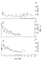
- Figures 4 depict inverse logs of formation porosity measured from samples obtained at selected intervals along the length of three separate wellbores.
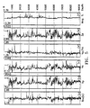
- Figures 5 depict inverse logs of formation density, compressional wave velocity (V p ), shear wave velocity (V s ), the ratio V p /V s , formation impedance and magnetic susceptibility, respectively.
- the sample interval for the inverse logs of Figure 5 is much finer than the minimum resolution thickness of conventional geophysical survey data. Consequently, such oversampling tends to produce inverse logs which have a very "spiky" appearance as depicted in Figure 5.
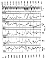
- the inverse logs of Figure 5 are smoothed with a smoothing operator having a wave length generally equal to the minimum resolution thickness of the geophysical survey data with which it is to be compared
- the inverse logs take on an appearance similar to those in Figures 6 (a-e).
- the inverse logs of Figure 6 (a-e) were smoothed with a smoothing operator having a minimum resolution thickness appropriate for seismic survey data.
- the synthetic traces of Figure 6 (f) were produced by convolving a wavelet signal having characteristics of a seismic source with the smoothed inverse impedance log of Figure 5 (e) and correspond well with actual seismic survey data.
- inverse logs of formation properties along the length of a well both during the drilling process and upon completion of the drilling process can be very important.
- the original geophysical survey data can be reprocessed to forecast depth to target.
- inverse logs of formation compressive strength obtained during the drilling process can provide the drillers with information important for controlling drilling parameters.
- the geophysical survey data can be calibrated to the physical properties represented in the inverse log.
- Figures 7a and 7b represent a seismic time section and an inverse log of formation impedance measured from samples obtained at selected intervals along the length of a wellbore.
- the inverse impedance log of Figure 7b was obtained at a well site indicated by the derrick structure in Figure 7a.
- the geophysical survey data in this case the seismic survey data
- geophysicists can then use the calibrated geophysical survey data to extrapolate the physical properties to remote locations in a basin.
- the present invention seeks to provide a novel method of and apparatus for obtaining selected physical properties from samples of the earth's subterranean formations surrounding a wellbore and developing inverse logs of the selected physical properties along the length of the wellbore.
- Explorationists can employ such inverse logs of the selected physical properties to perform basin analysis whereby the physical properties obtained at one or more wellbores can be used to calibrate geophysical survey data at each wellbore location and then extrapolate such physical properties to other locations in the basin with the geophysical survey data so as to evaluate the oil- and gas-bearing potential of the earth's subterranean formations.
Landscapes
- Physics & Mathematics (AREA)
- Life Sciences & Earth Sciences (AREA)
- General Life Sciences & Earth Sciences (AREA)
- General Physics & Mathematics (AREA)
- Geophysics (AREA)
- Geophysics And Detection Of Objects (AREA)
Claims (11)
- Vorrichtung zur Bearbeitung einer Vielzahl von Proben der Untergrundformationen der Erde, um für jede Probe eine Vielzahl von für die Gegebenheit in deren ursprünglicher Lage repräsentativen physikalischen Eigenschaften zu erhalten, die umfaßt:(a) ein einziges maschinenlesbares Probencodeetikett für jede Probe;(b) eine Vielzahl von Meßstationen (10, 20, 30, 40, 50, 60) zur Messung einer Vielzahl von ausgewählten physikalischen Eigenschaften, in welcher jede Meßstation zum Messen von wenigstens einer physikalischen Eigenschaft jeder Probe angepaßt ist und in welcher es für jede Meßstation einen einzigen maschinenlesbaren Stationscode gibt;(c) Lesemittel (70) zum Lesen der Probencodes und Stationscodes für eine Probe an einer ausgewählten Meßstation; und(d) zentrales Datenverarbeitungsmittel (CPU) zum Einleiten der Messung von wenigstens einer physikalischen Eigenschaft einer Probe an einer ausgewählten Meßstation nach Eingang eines Stationscodes und eines Probencodes vom Lesemittel und zum Speichern der Messung der physikalischen Eigenschaft.
- Vorrichtung gemäß Anspruch 1, die weiterhin einschließt:
Anzeigemittel (80, 90) zum Anzeigen inverser Auftragungen von ausgewählten physikalischen Eigenschaften aus im zentralen Datenverarbeitungsmittel gespeicherten Messungen als eine Funktion der Tiefe in einem Bohrschacht. - Vorrichtung gemäß Anspruch 1 oder 2, die weiterhin einschließt:
Mittel (95) zur Übertragung von Messungen physikalischer Eigenschaften zu einem zentralen Standort. - Vorrichtung gemäß Anspruch 1, 2 oder 3, in welcher die Meßstationen Mittel zum Messen von wenigstens einer der physikalischen Eigenschaften Formationsdichte, Druckwellengeschwindigkeit, Schubwellengeschwindigkeit, Druckfestigkeit, Porosität und magnetische Suszeptibilität einschließen.
- Ein Verfahren zur Bearbeitung einer Vielzahl von Proben von Untergrundformationen der Erde an einer Vielzahl von Meßstationen (10, 20, 30, 40, 50, 60), um für jede Probe eine Vielzahl von für die Gegebenheit in deren ursprünglicher Lage repräsentativen physikalischen Eigenschaften zu erhalten, das die Schritte umfaßt:(a) Etikettieren jeder Probe mit einem einzigen maschinenlesbaren Probencode;(b) Zuteilung eines einzigen maschinenlesbaren Stationscodes zu jeder Meßstation;(c) Maschinelles Einlesen des Probencodes und Stationscodes einer Probe an einer ausgewählten Meßstation in eine zentrale Recheneinheit (CPU); und(d) Einrichten der zentralen Recheneinheit zur Reaktion auf den Eingang des Probencodes und des Stationscodes, zum Einleiten einer Messung von wenigstens einer physikalischen Eigenschaft der Probe an der ausgewählten Meßstation und zum Speichern der Messung der physikalischen Eigenschaft.
- Ein Verfahren gemäß Anspruch 5, das weiter den Schritt der asynchronen Bearbeitung einer Vielzahl von Proben durch eine Vielzahl von Meßstationen einschließt, um wenigstens eine verschiedene physikalische Eigenschaft an jeder Meßstation zu erhalten bis jede Probe an jeder Meßstation war.
- Ein Verfahren gemäß Anspruch 5 oder 6, in welchem dem Schritt der Etikettierung jeder Probe der Schritt des Erhalts einer Vielzahl von einen Bohrschacht in ausgewählten Abständen entlang dessen Länge umgebenden Proben von den Untergrundformationen der Erde vorausgeht.
- Ein Verfahren gemäß Anspruch 7, das weiter die Schritte einschließt:(a) Erzeugung einer inversen Auftragung von wenigstens einer ausgewählten für die Gegebenheit in ihrer ursprünglicher Lage entlang der Länge des Bohrschachts repräsentativen physikalischen Eigenschaft;(b) Kalibrieren eines Satzes von geophysikalischen den Standort des Bohrschachtes einschließenden Vermessungsdaten durch Anwendung der inversen Auftragung; und(c) Extrapolation der ausgewählten physikalischen Eigenschaft auf einen vom Standort des Bohrschachts entfernten Standort unter Verwendung der kalibrierten geophysikalischen Vermessungsdaten.
- Ein Verfahren gemäß Anspruch 8, in welchem für jede durch den Bohrschacht durchquerte Lithologie entlang seiner Länge Proben erhalten werden.
- Ein Verfahren gemäß Anspruch 8 oder 9, in welchem Proben in wenigstens der minimalen Auflösungsstärke der zu kalibrierenden geophysikalischen Vermessungsdaten entsprechenden Abständen erhalten werden.
- Ein Verfahren gemäß Anspruch 8, 9 oder 10, das weiter den Schritt der Glättung der inversen Auftragung von einer physikalischen Eigenschaft mit einem Glättungsoperator einschließt, der eine der minimalen Auflösungsstärke der zu kalibrierenden geophysikalischen Vermessungsdaten vergleichbare Wellenlänge hat.
Applications Claiming Priority (2)
| Application Number | Priority Date | Filing Date | Title |
|---|---|---|---|
| US264917 | 1981-05-18 | ||
| US26491788A | 1988-10-31 | 1988-10-31 |
Publications (3)
| Publication Number | Publication Date |
|---|---|
| EP0367495A2 EP0367495A2 (de) | 1990-05-09 |
| EP0367495A3 EP0367495A3 (de) | 1992-03-04 |
| EP0367495B1 true EP0367495B1 (de) | 1994-05-04 |
Family
ID=23008178
Family Applications (1)
| Application Number | Title | Priority Date | Filing Date |
|---|---|---|---|
| EP89311046A Expired - Lifetime EP0367495B1 (de) | 1988-10-31 | 1989-10-26 | Öl- und Gasexplorationsverfahren und -anordnung |
Country Status (5)
| Country | Link |
|---|---|
| US (1) | US5134271A (de) |
| EP (1) | EP0367495B1 (de) |
| CA (1) | CA1315191C (de) |
| DE (1) | DE68915116T2 (de) |
| EG (1) | EG18740A (de) |
Cited By (1)
| Publication number | Priority date | Publication date | Assignee | Title |
|---|---|---|---|---|
| US9638830B2 (en) | 2007-12-14 | 2017-05-02 | Westerngeco L.L.C. | Optimizing drilling operations using petrotechnical data |
Families Citing this family (21)
| Publication number | Priority date | Publication date | Assignee | Title |
|---|---|---|---|---|
| IT1277377B1 (it) * | 1995-07-28 | 1997-11-10 | Agip Spa | Metodo per l'aggiornamento continuo dell'immagine sismica bidimensionale e tridimensionale in profondita' mediante |
| RU2177545C2 (ru) * | 1997-01-16 | 2001-12-27 | Ухтинский государственный технический университет | Способ разведки нефтегазовых месторождений |
| US6516080B1 (en) | 2000-04-05 | 2003-02-04 | The Board Of Trustees Of The Leland Stanford Junior University | Numerical method of estimating physical properties of three-dimensional porous media |
| GB0018480D0 (en) * | 2000-07-27 | 2000-09-13 | Geco Prakla Uk Ltd | A method of processing surface seismic data |
| US6816787B2 (en) | 2003-03-31 | 2004-11-09 | Schlumberger Technology Corporation | Generating and displaying a virtual core and a virtual plug associated with a selected piece of the virtual core |
| FI121393B (fi) | 2003-04-11 | 2010-10-29 | Sandvik Mining & Constr Oy | Menetelmä ja järjestelmä porareikätiedon hallitsemiseksi |
| US20060047429A1 (en) | 2004-08-24 | 2006-03-02 | Adams Steven L | Method of estimating geological formation depths by converting interpreted seismic horizons from the time domain to the depth domain |
| US7293715B2 (en) * | 2004-12-16 | 2007-11-13 | Schlumberger Technology Corporation | Marking system and method |
| US7478219B2 (en) * | 2005-04-14 | 2009-01-13 | International Business Machines Corporation | Retrieving event data for logical partitions |
| US8064287B2 (en) | 2006-12-28 | 2011-11-22 | Rock Solid Images, Inc. | Method for interpreting seismic data and controlled source electromagnetic data to estimate subsurface reservoir properties |
| US20080162050A1 (en) * | 2006-12-28 | 2008-07-03 | Peter Harris | Method for interpreting seismic data and controlled source electromagnetic data to estimate subsurface reservoir properties |
| US20140089835A1 (en) * | 2012-09-21 | 2014-03-27 | EVCO Plastics | Application for Core Drilling |
| US10884084B2 (en) | 2013-09-05 | 2021-01-05 | Saudi Arabian Oil Company | Systems and methods for tri-axial NMR testing |
| US10048336B2 (en) | 2013-09-05 | 2018-08-14 | Saudi Arabian Oil Company | Tri-axial NMR test instrument |
| US11241701B2 (en) | 2013-10-21 | 2022-02-08 | Saudi Arabian Oil Company | Tri-axial centrifuge apparatus with electrical sensor, acoustic sensor, and x-ray instrument |
| CN107290799B (zh) * | 2016-03-30 | 2019-06-18 | 中国石油化工股份有限公司 | 一种岩石可压性的确定方法 |
| CA3035978C (en) | 2016-09-09 | 2021-05-18 | Bly Ip Inc. | Systems and methods for analyzing core using x-ray fluorescence |
| CN106324701B (zh) * | 2016-10-10 | 2018-06-19 | 中国海洋石油总公司 | 基于断-隆联动含油气盆地分析方法 |
| US11709287B2 (en) | 2019-11-15 | 2023-07-25 | Saudi Arabian Oil Company | Well logging to identify low resistivity pay zones in a subterranean formation using elastic attributes |
| US11692973B2 (en) | 2021-01-04 | 2023-07-04 | Saudi Arabian Oil Company | Determination of reservoir heterogeneity |
| CN113187559B (zh) * | 2021-05-31 | 2024-06-18 | 煤炭科学研究总院有限公司 | 矿井安全预警方法及装置 |
Family Cites Families (14)
| Publication number | Priority date | Publication date | Assignee | Title |
|---|---|---|---|---|
| US2458093A (en) * | 1949-01-04 | Method of determining the fluid content of well cores | ||
| US2531083A (en) * | 1944-10-16 | 1950-11-21 | Alonzo L Smith | Core analysis |
| US2613250A (en) * | 1950-10-06 | 1952-10-07 | Atlantic Refining Co | Method for measuring resistivity of earth samples |
| US3373440A (en) * | 1966-02-01 | 1968-03-12 | Core Lab Inc | Apparatus for photographing well core samples |
| GB1561061A (en) * | 1976-03-17 | 1980-02-13 | Hycel Inc | Reaction conveyor assembly in an automatic chemical testing apparatus |
| GB1587171A (en) * | 1977-04-15 | 1981-04-01 | Vickers Ltd | Bar-coded data reading terminals |
| GB1584060A (en) * | 1977-09-13 | 1981-02-04 | Schlumberger Ltd | Processing well logging data for example for verification and calibration of well logs |
| US4227404A (en) * | 1978-04-17 | 1980-10-14 | Century Geophysical Corporation | Digital mineral logging system |
| US4263509A (en) * | 1979-02-26 | 1981-04-21 | Dresser Industries, Inc. | Method for in situ determination of the cation exchange capacities of subsurface formations |
| US4569421A (en) * | 1980-11-17 | 1986-02-11 | Sandstedt Gary O | Restaurant or retail vending facility |
| US4537150A (en) * | 1984-02-13 | 1985-08-27 | Bowers David L | Data entry systems |
| US4835372A (en) * | 1985-07-19 | 1989-05-30 | Clincom Incorporated | Patient care system |
| US4854163A (en) * | 1987-09-28 | 1989-08-08 | Amoco Corporation | Beltless core conveyor system for wellsite analysis |
| US4916441A (en) * | 1988-09-19 | 1990-04-10 | Clinicom Incorporated | Portable handheld terminal |
-
1989
- 1989-07-19 CA CA000606112A patent/CA1315191C/en not_active Expired - Fee Related
- 1989-10-26 EP EP89311046A patent/EP0367495B1/de not_active Expired - Lifetime
- 1989-10-26 DE DE68915116T patent/DE68915116T2/de not_active Expired - Fee Related
- 1989-10-29 EG EG51989A patent/EG18740A/xx active
-
1991
- 1991-03-06 US US07/665,211 patent/US5134271A/en not_active Expired - Fee Related
Cited By (1)
| Publication number | Priority date | Publication date | Assignee | Title |
|---|---|---|---|---|
| US9638830B2 (en) | 2007-12-14 | 2017-05-02 | Westerngeco L.L.C. | Optimizing drilling operations using petrotechnical data |
Also Published As
| Publication number | Publication date |
|---|---|
| EG18740A (en) | 1993-12-30 |
| EP0367495A3 (de) | 1992-03-04 |
| DE68915116T2 (de) | 1994-08-18 |
| DE68915116D1 (de) | 1994-06-09 |
| CA1315191C (en) | 1993-03-30 |
| EP0367495A2 (de) | 1990-05-09 |
| US5134271A (en) | 1992-07-28 |
Similar Documents
| Publication | Publication Date | Title |
|---|---|---|
| EP0367495B1 (de) | Öl- und Gasexplorationsverfahren und -anordnung | |
| US5012674A (en) | Method of exploration for hydrocarbons | |
| US5511037A (en) | Comprehensive method of processing measurement while drilling data from one or more sensors | |
| US6611761B2 (en) | Sonic well logging for radial profiling | |
| US6237404B1 (en) | Apparatus and method for determining a drilling mode to optimize formation evaluation measurements | |
| US4517836A (en) | Method for determining oil saturation in a subsurface formation | |
| US20080151690A1 (en) | Imaging Near-Borehole Reflectors Using Shear Wave Reflections From a Multi-Component Acoustic Tool | |
| US5109697A (en) | Method of exploration for hydrocarbons | |
| US6167348A (en) | Method and apparatus for ascertaining a characteristic of a geological formation | |
| US6718265B2 (en) | Petrophysical property estimation using an acoustic calibration relationship | |
| US4484470A (en) | Method and apparatus for determining characteristics of clay-bearing formations | |
| US5126939A (en) | Method for estimating the organic matter content of sedimentary rocks from data recorded in wells by well-logging probes | |
| Holt et al. | Petrophysical laboratory measurements for basin and reservoir evaluation | |
| US7254486B2 (en) | Method and apparatus for shale bed detection in deviated and horizontal wellbores | |
| Almén et al. | Aespoe hard rock laboratory. Field investigation methodology and instruments used in the preinvestigation phase, 1986-1990 | |
| Schmoker | Accuracy of borehole gravity data | |
| Koerperich | Shear Wave Velocities Determined From Long-and Short-Spaced Borehole Acoustic Devices | |
| US7649169B2 (en) | Method for determining shale bed boundaries and gamma ray activity with gamma ray instrument | |
| Paillet et al. | Downhole applications of geophysics | |
| Worthington | The direction of petrophysics: a five-year perspective | |
| CN114624772B (zh) | 无声波曲线井的井震标定方法、装置、设备及存储介质 | |
| Nelson et al. | Assessment of geophysical logs from borehole USW G-2, Yucca Mountain, Nevada | |
| Ramirez et al. | Applications of well logging for compaction and subsidence studies in the Orinoco oil belt, Venezuela | |
| Grilli et al. | Sonic Log Quality Control: A Mandatory Workflow to Ensure Reliable Results in Different Disciplines | |
| Shipley et al. | Shipboard Scientific Party2 |
Legal Events
| Date | Code | Title | Description |
|---|---|---|---|
| PUAI | Public reference made under article 153(3) epc to a published international application that has entered the european phase |
Free format text: ORIGINAL CODE: 0009012 |
|
| AK | Designated contracting states |
Kind code of ref document: A2 Designated state(s): BE DE FR GB NL |
|
| 17P | Request for examination filed |
Effective date: 19901203 |
|
| PUAL | Search report despatched |
Free format text: ORIGINAL CODE: 0009013 |
|
| AK | Designated contracting states |
Kind code of ref document: A3 Designated state(s): BE DE FR GB NL |
|
| 17Q | First examination report despatched |
Effective date: 19930114 |
|
| GRAA | (expected) grant |
Free format text: ORIGINAL CODE: 0009210 |
|
| AK | Designated contracting states |
Kind code of ref document: B1 Designated state(s): BE DE FR GB NL |
|
| REF | Corresponds to: |
Ref document number: 68915116 Country of ref document: DE Date of ref document: 19940609 |
|
| ET | Fr: translation filed | ||
| PLBE | No opposition filed within time limit |
Free format text: ORIGINAL CODE: 0009261 |
|
| STAA | Information on the status of an ep patent application or granted ep patent |
Free format text: STATUS: NO OPPOSITION FILED WITHIN TIME LIMIT |
|
| 26N | No opposition filed | ||
| PGFP | Annual fee paid to national office [announced via postgrant information from national office to epo] |
Ref country code: FR Payment date: 19980930 Year of fee payment: 10 |
|
| PGFP | Annual fee paid to national office [announced via postgrant information from national office to epo] |
Ref country code: DE Payment date: 19981002 Year of fee payment: 10 |
|
| PGFP | Annual fee paid to national office [announced via postgrant information from national office to epo] |
Ref country code: GB Payment date: 19981015 Year of fee payment: 10 |
|
| PGFP | Annual fee paid to national office [announced via postgrant information from national office to epo] |
Ref country code: NL Payment date: 19981020 Year of fee payment: 10 |
|
| PGFP | Annual fee paid to national office [announced via postgrant information from national office to epo] |
Ref country code: BE Payment date: 19981021 Year of fee payment: 10 |
|
| PG25 | Lapsed in a contracting state [announced via postgrant information from national office to epo] |
Ref country code: GB Free format text: LAPSE BECAUSE OF NON-PAYMENT OF DUE FEES Effective date: 19991026 |
|
| PG25 | Lapsed in a contracting state [announced via postgrant information from national office to epo] |
Ref country code: BE Free format text: LAPSE BECAUSE OF NON-PAYMENT OF DUE FEES Effective date: 19991031 |
|
| BERE | Be: lapsed |
Owner name: AMOCO CORP. Effective date: 19991031 |
|
| PG25 | Lapsed in a contracting state [announced via postgrant information from national office to epo] |
Ref country code: NL Free format text: LAPSE BECAUSE OF NON-PAYMENT OF DUE FEES Effective date: 20000501 |
|
| GBPC | Gb: european patent ceased through non-payment of renewal fee |
Effective date: 19991026 |
|
| PG25 | Lapsed in a contracting state [announced via postgrant information from national office to epo] |
Ref country code: FR Free format text: LAPSE BECAUSE OF NON-PAYMENT OF DUE FEES Effective date: 20000630 |
|
| NLV4 | Nl: lapsed or anulled due to non-payment of the annual fee |
Effective date: 20000501 |
|
| PG25 | Lapsed in a contracting state [announced via postgrant information from national office to epo] |
Ref country code: DE Free format text: LAPSE BECAUSE OF NON-PAYMENT OF DUE FEES Effective date: 20000801 |
|
| REG | Reference to a national code |
Ref country code: FR Ref legal event code: ST |