EP0367517B1 - Dispositif d'enlèvement des copeaux pour machine-outil multibroche - Google Patents
Dispositif d'enlèvement des copeaux pour machine-outil multibroche Download PDFInfo
- Publication number
- EP0367517B1 EP0367517B1 EP89311143A EP89311143A EP0367517B1 EP 0367517 B1 EP0367517 B1 EP 0367517B1 EP 89311143 A EP89311143 A EP 89311143A EP 89311143 A EP89311143 A EP 89311143A EP 0367517 B1 EP0367517 B1 EP 0367517B1
- Authority
- EP
- European Patent Office
- Prior art keywords
- duct
- removing device
- working heads
- head
- chip removing
- Prior art date
- Legal status (The legal status is an assumption and is not a legal conclusion. Google has not performed a legal analysis and makes no representation as to the accuracy of the status listed.)
- Expired - Lifetime
Links
- 239000000428 dust Substances 0.000 description 4
- 239000002023 wood Substances 0.000 description 4
- 238000010276 construction Methods 0.000 description 3
- 230000004048 modification Effects 0.000 description 3
- 238000012986 modification Methods 0.000 description 3
- 238000012423 maintenance Methods 0.000 description 2
- 230000002093 peripheral effect Effects 0.000 description 2
- 230000006835 compression Effects 0.000 description 1
- 238000007906 compression Methods 0.000 description 1
- 230000000694 effects Effects 0.000 description 1
- 238000012856 packing Methods 0.000 description 1
- 238000007789 sealing Methods 0.000 description 1
Images





Classifications
-
- B—PERFORMING OPERATIONS; TRANSPORTING
- B23—MACHINE TOOLS; METAL-WORKING NOT OTHERWISE PROVIDED FOR
- B23Q—DETAILS, COMPONENTS, OR ACCESSORIES FOR MACHINE TOOLS, e.g. ARRANGEMENTS FOR COPYING OR CONTROLLING; MACHINE TOOLS IN GENERAL CHARACTERISED BY THE CONSTRUCTION OF PARTICULAR DETAILS OR COMPONENTS; COMBINATIONS OR ASSOCIATIONS OF METAL-WORKING MACHINES, NOT DIRECTED TO A PARTICULAR RESULT
- B23Q11/00—Accessories fitted to machine tools for keeping tools or parts of the machine in good working condition or for cooling work; Safety devices specially combined with or arranged in, or specially adapted for use in connection with, machine tools
- B23Q11/0042—Devices for removing chips
- B23Q11/0046—Devices for removing chips by sucking
-
- B—PERFORMING OPERATIONS; TRANSPORTING
- B23—MACHINE TOOLS; METAL-WORKING NOT OTHERWISE PROVIDED FOR
- B23Q—DETAILS, COMPONENTS, OR ACCESSORIES FOR MACHINE TOOLS, e.g. ARRANGEMENTS FOR COPYING OR CONTROLLING; MACHINE TOOLS IN GENERAL CHARACTERISED BY THE CONSTRUCTION OF PARTICULAR DETAILS OR COMPONENTS; COMBINATIONS OR ASSOCIATIONS OF METAL-WORKING MACHINES, NOT DIRECTED TO A PARTICULAR RESULT
- B23Q11/00—Accessories fitted to machine tools for keeping tools or parts of the machine in good working condition or for cooling work; Safety devices specially combined with or arranged in, or specially adapted for use in connection with, machine tools
- B23Q11/08—Protective coverings for parts of machine tools; Splash guards
- B23Q11/0825—Relatively slidable coverings, e.g. telescopic
-
- Y—GENERAL TAGGING OF NEW TECHNOLOGICAL DEVELOPMENTS; GENERAL TAGGING OF CROSS-SECTIONAL TECHNOLOGIES SPANNING OVER SEVERAL SECTIONS OF THE IPC; TECHNICAL SUBJECTS COVERED BY FORMER USPC CROSS-REFERENCE ART COLLECTIONS [XRACs] AND DIGESTS
- Y10—TECHNICAL SUBJECTS COVERED BY FORMER USPC
- Y10T—TECHNICAL SUBJECTS COVERED BY FORMER US CLASSIFICATION
- Y10T408/00—Cutting by use of rotating axially moving tool
- Y10T408/50—Cutting by use of rotating axially moving tool with product handling or receiving means
-
- Y—GENERAL TAGGING OF NEW TECHNOLOGICAL DEVELOPMENTS; GENERAL TAGGING OF CROSS-SECTIONAL TECHNOLOGIES SPANNING OVER SEVERAL SECTIONS OF THE IPC; TECHNICAL SUBJECTS COVERED BY FORMER USPC CROSS-REFERENCE ART COLLECTIONS [XRACs] AND DIGESTS
- Y10—TECHNICAL SUBJECTS COVERED BY FORMER USPC
- Y10T—TECHNICAL SUBJECTS COVERED BY FORMER US CLASSIFICATION
- Y10T409/00—Gear cutting, milling, or planing
- Y10T409/30—Milling
- Y10T409/30392—Milling with means to protect operative or machine [e.g., guard, safety device, etc.]
-
- Y—GENERAL TAGGING OF NEW TECHNOLOGICAL DEVELOPMENTS; GENERAL TAGGING OF CROSS-SECTIONAL TECHNOLOGIES SPANNING OVER SEVERAL SECTIONS OF THE IPC; TECHNICAL SUBJECTS COVERED BY FORMER USPC CROSS-REFERENCE ART COLLECTIONS [XRACs] AND DIGESTS
- Y10—TECHNICAL SUBJECTS COVERED BY FORMER USPC
- Y10T—TECHNICAL SUBJECTS COVERED BY FORMER US CLASSIFICATION
- Y10T409/00—Gear cutting, milling, or planing
- Y10T409/30—Milling
- Y10T409/304088—Milling with means to remove chip
Definitions
- This invention relates to a chip removing device for removing, in a multi-head machine tool such as a wood working machine of the type wherein a plurality of working heads are selectively used, chips of wood or the like from around the working heads by way of vacuum suction while working of the workpiece is proceeding.
- a chip removing device of the type mentioned has been already proposed by the inventor of the present patent application.
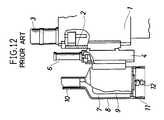
- the chip removing device is disclosed in Japanese Utility Model Publication No. 13605/1985 and has such a structure as shown in FIGS. 11 and 12.
- a multi-head machine tool in which the chip removing device is incorporated includes a column 1 and a ram 2 mounted for vertical up and down movement on the column 1 and connected to be moved up and down by a motor 3.
- a plurality of, for example, four, head holders 4 are mounted in a leftward and rightward juxtaposed relationship on the ram 2.
- a working head 5 is mounted for up and down movement on each of the head holders 4 and connected to be shifted between an upper position and a lower position by an air cylinder 6.
- Each of the working heads 5 is constructed such that a motor 9 is supported at the center within a hood 8 in which a plurality of suction air passages 7 are defined, and a connecting pipe 10 is secured vertically at the top end of the hood 8 while a brush 11 is provided vertically downwardly on a peripheral edge at the bottom end of the hood 8.
- a tool 12 such as a router can be removably mounted on a rotary shaft of each of the motors 9.
- a duct 13 extends in a horizontal direction on the ram 2.
- Upper end portions of the connecting pipes 10 of the four working heads 5 are fitted for individual up and down sliding movement in an airtight condition in four holes 14 formed in a lower wall of the duct 13 and extend into the duct 13.
- Four valve devices 15 corresponding to the four working heads 5 are provided in a juxtaposed relationship in the duct 13.
- Each of the valve devices 15 includes a valve plate 17 mounted for up and down sliding movement on four guide rods 16 which are securely mounted on and extends vertically upwardly from the lower wall of the duct 13.
- Each of the valve plates 17 is normally urged downwardly by a compression coil spring 18.
- each of the valve plates 17 can be moved down only to a predetermined vertical position at which it contacts with the corresponding stoppers 19.
- a seal member 21 is provided on a lower face of each of the valve plates 17 for closing an upper end opening 20 of the corresponding connecting pipe 10 in an airtight condition.
- the duct 13 is connected to a vacuum duct collector not shown. Only an arbitrary one of the four working heads 5 which is to be actually used is shifted to the lower position by the corresponding air cylinder 6 while the other working heads 5 are kept at their upper positions.
- the connecting pipes 10 of those of the working heads 5 which are kept at the upper positions keep, against the springs 18, the valve plates 17 at corresponding higher positions at which the upper end openings 20 thereof are pressed against and closed in an airtight, condition by the seal members 21 to disconnect the suction air passages of the hoods 8 from the duct 13. Consequently, a sucking operation by way of the suction air passages 7 does not take place in the working heads 5 which are kept at the upper positions.
- the suction air passage 7 of a working head 5 which is positioned at the lower position is connected to the duct 13 by way of the corresponding connecting pipe 10 since the upper end opening 20 of the connecting pipe 10 is positioned below the vertical position of the stopper 19 and thus spaced away from the corresponding seal member 21. Accordingly, chips of wood or the like cut off by the tool 12 mounted on the working head 5 are sucked into the suction air passage 7 and introduced into the duct 13 by way of the connecting pipe 10 whereafter they are transported to a collecting station by way of the duct 13.
- the conventional device has the following drawbacks.
- valve devices 15 which are complicated in construction must be provided individually for the working heads 5, which requires a correspondingly high cost.
- valve devices 15 are provided in the duct 13, maintenance thereof is very cumbersome.
- valve devices 15 are secured at predetermined positions in the duct 13 such that they may correspond individually to the working heads 5, while the head holder 4 is constructed for leftward and rightward movement relative to the ram 2, the distance between adjacent ones of the working heads 5 can be adjusted but only by a very limited amount.
- the multi-head machine tool includes a carriage 32 mounted on a front face of a column 30 which is provided uprightly at the center of the machine tool. More particularly, the carrier 32 is mounted for leftward and rightward sliding movement on and along a pair of upper and lower horizontal rails 31 provided horizontally on the front face of the column 30. A pair of left and right vertical rails 33 are provided vertically on a front face of the carriage 32, and a horizontally elongated ram 32 is mounted for up and down sliding movement on and along the vertical rails 33.
- the ram 34 is connected to a motor 35 carried on the carriage 32 such that, when a screw shaft not shown is rotated by the motor 35, rotation thereof is transmitted as linear motion to the ram 34 by way of a motion converting mechanism not shown to move the ram 34 upwardly or downwardly in accordance with the direction of rotation of the motor 35.
- a pair of upper and lower horizontal rails 36 are provided horizontally on a front face of the ram 34, and a plurality of, for example, four, vertically elongated head holders 37 are mounted for leftward and rightward sliding movement along the horizontal rails 36. Further, a pair of upper and lower screw shafts 38 and another pair of upper and lower screw shafts 39 are horizontally supported for individual rotation at left and right locations on the front face of the ram 34.
- the left-hand side upper and lower screw shafts 38 are supported for rotation by a central bearing 40 provided at the center of the front face of the ram 34 and a left-hand side bearing 41 provided at the left end of the front face of the ram 34 while the right-hand side upper and lower screw shafts 39 are supported for rotation by the center bearing 40 and a right-hand side bearing 42 provided at the right end of the front face of the ram 34.
- the two left-hand side screw shafts 38 are individually screwed in female threaded portions 43 of two left-hand side ones of the head holders 37 while the other two right-hand side screw shafts 39 are individually screwed in female threaded portions 44 of the other two right-hand side head holders 38.
- a working head 45 having such a construction as described below is mounted on a front face of each of the head holders 37.
- each of the working heads 45 has a mounting base portion 47 provided in an integral relationship thereon behind a corresponding hood 46 and has a plurality of suction air passages 48 defined in a circumferential direction within the hood 46.
- a motor 49 is supported at the center of the hood 46, and a connecting pipe 50 is fixed vertically to the top end of the hood 46 while a brush 51 is provided vertically downwardly along a peripheral edge of the bottom end of the hood 46.
- a tool 52 such as a router is removably mounted on a rotary shaft of the motor 49.
- each of the working heads 45 is supported for up and down sliding movement along a pair of left and right vertical rails 53 provided vertically on the front face of the corresponding head holder 37 and is suspended on a piston rod 55 of an air cylinder 54 mounted on the corresponding head holder 37.
- each of the working heads 45 can be individually shifted between upper and lower positions by the air cylinder 54 on the corresponding head holder 37. Further, the four head holders 37 can be slidably moved leftwardly or rightwardly individually along the upper and lower horizontal rails 36 by rotating the corresponding screw shafts 38 or 39. Consequently, the distance between adjacent ones of the four working heads can be adjusted arbitrarily.
- a duct 56 in the form of a rectangular tube common to the four working heads 45 is provided horizontally on the ram 34 by means of a bracket 57.
- the duct 56 is closed at one end but is open at the other end thereof, and the open end of the duct 56 is connected to a vacuum dust collector not shown by way of a hose or the like not shown so that dust may be sucked from the duct 56 into the vacuum dust collector.
- the duct 56 has a longitudinally elongated slit 59 formed in a lower wall thereof while a seal plate 61 formed from a rubber plate or the like having a substantially same length as that of the slit 59 is adhered to a lower face of an upper wall 60 of the duct 56.
- a rail frame 62 is securely mounted on a lower face of the lower wall 58 of the duct 56 covering the entire area of the slit 59.
- the rail frame 62 has a pair of front and rear rail portions 63 on each of which a large guide groove 64 is provided, and a plurality of small guide grooves 65 are formed parallelly in a predetermined spaced relationship in a vertical direction on the bottom of each of the guide grooves 65.
- Four rectangular flange members 66 through which the connecting pipes 50 of the working heads 45 individually extend in such a manner as hereinafter described are fitted for sliding movement in the large guide grooves 64 of the rail frame 62 while a large number of slide plates 67 for cooperating with each other to interconnecting the flange members 66 are fitted for sliding movement in the small guide grooves 65.
- a continuous shutter 68 which normally closes the slit 59 of the lower wall 58 of the duct 56 is thus generally constructed by the four flange members 66 and the large number of slide plates 67.
- the opposite end ones of the slide plates 67 of the shutter 68 are secured to rail frame 62 adjacent the opposite longitudinal ends of the slit 59 while those of the slide plates 67 which are positioned on the opposite sides of each of the flange members 66 are fixed to the opposite side faces of the flange member 66.
- Each of the slide plates 67 has at the opposite ends thereof a pair of bent portions 69 and 70 which extend in the vertically opposite directions such that the opposite ends thereof may individually contact for sliding movement with lower and upper faces of the opposite adjacent slide plates 67 and adjacent bent portions 69 and 70 of each adjacent ones of the slide plates 67 may engage with each other.
- Each of the flange members 66 has a through-hole 71 formed therein, and the connecting pipes 50 are individually fitted for sliding up and down movement in the through-holes 71 of the flange members 66.
- a packing 72 is provided in each of the through-holes 71 for sealing between the corresponding connecting pipe 50 and flange member 66 in an airtight condition.
- the connecting pipe 50 is acted upon by a vacuum sucking action. Accordingly, at the working head 45 at the lower position, when wood or the like is machined by the tool 52, chips cut off then are sucked into the suction air passage 48 of the hood 46 and then introduced into the duct 56 by way of the connecting pipe 50 whereafter they are transported to the dust collecting station by way of the duct 56.
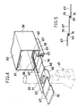
- a seal member 74 should be provided on at least one of the bent portions 69 and 70 of each of the slide plates 67 as shown in FIG. 5 in order to improve the airtight property between each adjacent slide plates 67.
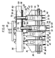
- FIGS. 6 to 8 there is shown a chip removing device for a multi-head machine tool according to a second embodiment of the present invention.
- the chip removing device is a modification to the chip removing device of the first embodiment and is only different in its shutter for closing the slit 59 of the duct 56.
- a bellows 75 extends between each adjacent ones of the four flange members 66 through which the connecting pipes 50 of the four working heads 45 extend and also between each of the opposite end flange members 66 and a corresponding portion of the rail frame 62 adjacent the slit 59.
- the bellows 75 are fitted for sliding movement to expand or contract themselves in the guide grooves 64 of the front and rear rail portions 63 of the rail frame 62.
- the flange members 66 and the bellows 75 thus construct the shutter 68 as a whole.
- the chip removing device of the present embodiment there is the possibility that chips may be accumulated between adjacent corrugations of the bellows 75 to hinder expanding and contracting movement of the bellows 75 while the chip removing device of the first embodiment is free from the problem because chips will slip on the slide plates 67.
- the chip removing device of the second embodiment is simpler in structure than the chip removing device of the first embodiment described above.
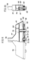
- the modified duct generally denoted at 76 is closed at the longitudinal opposite ends thereof, but has a connecting opening 78 at the center of a trapezoidal projection 77 extending upwardly therefrom so that chips may be sucked by way of the connecting opening 78 from the inside of the duct 76. Meanwhile, a seal plate 61 is adhered to a lower face of a receiving plate 79 provided horizontally at an intermediate vertical position within the duct 76.
- the top end openings 73 of the connecting pipes 50 are directed in the same direction as the direction in which chips are sucked by way of the connecting port 78, and consequently, the vacuum sucking effect is higher than those in the chip removing devices of the first and second embodiments described hereinabove.
Landscapes
- Engineering & Computer Science (AREA)
- Mechanical Engineering (AREA)
- Auxiliary Devices For Machine Tools (AREA)
Claims (5)
- Dispositif d'enlèvement de copeaux pour une machine-outil multibroche, dans laquelle plusieurs têtes de travail (45), comprenant chacune un moteur (49), sont montées de manière à être déplacées individuellement horizontalement dans des directions opposées sur un chariot de tourelle (34) au moyen de porte-têtes individuels (37) et sont chacune montées pour être déplacées entre une position supérieure et une position inférieure au moyen d'un vérin (54), comportant des moyens (46) pour définir autour de chaque moteur (49) un passage d'air d'aspiration, un tube de raccordement (50) partant d'une portion supérieure de chaque tête de travail (45), un conduit commun horizontal (56) raccordé en commun aux tubes de raccordement (50) pour provoquer une action d'aspiration s'exerçant sur les têtes de travail (45) pour recueillir ainsi les copeaux produits par les têtes de travail (45), caractérisé en ce que ledit conduit a une fente horizontalement allongée (59) formée dans sa paroi inférieure, des moyens d'écran extensibles (68) pour fermer ladite fente (59), des portions terminales supérieures de ces tubes de raccordement (50) s'étendant de manière hermétique à travers les moyens d'écran pour arriver dans le conduit (56), ces moyens d'écran (68) étant agencés pour permettre le mouvement horizontal des têtes de travail (45) de telle sorte que, lorsque l'une de ces têtes de travail (45) est déplacée horizontalement dans une direction ou dans l'autre, les moyens d'écran (68) s'étendent et se contractent partiellement sur les côtés opposés de ladite tête de travail (45) pour la suivre, et en ce qu'une plaque d'étanchéité horizontalement allongée (61) est fixée horizontalement à l'intérieur dudit conduit (56) et est disposée pour coopérer avec toutes les têtes de travail (45) de telle sorte que, lorsque chacune des têtes de travail (45) se trouve dans sa position haute, l'ouverture terminale supérieure du tube de raccordement (50) de la tête de travail considérée (45) est appliquée contre la plaque d'étanchéité (61) de telle sorte que celle-ci obture de façon hermétique ladite ouverture terminale supérieure, mais que, lorsque la tête de travail (45) se trouve dans sa position basse l'ouverture terminale supérieure de son tube de raccordement (50) est espacée de ladite plaque d'étanchéité (61) et est dégagée.
- Dispositif d'enlèvement de copeaux pour une machine-outil multibroche selon la revendication 1, dans lequel les moyens d'écran (68) sont constitués par un grand nombre de plaques coulissantes (67) logées, de façon à pouvoir coulisser, dans des rainures de guidage (65) formées dans les bords latéraux opposés de la fente (59) du conduit (56), ces plaques coulissantes (67) étant associées les unes avec les autres de manière qu'elles puissent se déplacer successivement lorsque l'une des têtes de travail (45) est déplacée dans une direction horizontale ou dans l'autre.
- Dispositif d'enlèvement de copeaux pour une machine-outil multibroche selon la revendication 1, dans lequel les moyens d'écran (68) comprennent un soufflet extensible (75).
- Dispositif d'enlèvement de copeaux pour une machine-outil multibroche selon la revendication 1, dans lequel la plaque d'étanchéité (61) est montée sur la face inférieure de la paroi supérieure du conduit (56).
- Dispositif d'enlèvement de copeaux pour une machine-outil multibroche selon la revendication 1, dans lequel la plaque d'étanchéité (61) est montée sur la face inférieure d'une plaque réceptrice (79) prévue dans une position verticalement intermédiaire à l'intérieur du conduit (56) de telle sorte qu'une action d'aspiration peut s'exercer au niveau de la portion verticalement intermédiaire à l'intérieur de ce conduit (56).
Applications Claiming Priority (4)
| Application Number | Priority Date | Filing Date | Title |
|---|---|---|---|
| JP14396188U JPH0529797Y2 (fr) | 1988-11-02 | 1988-11-02 | |
| JP143961/88U | 1988-11-02 | ||
| JP8606889A JPH02269540A (ja) | 1989-04-05 | 1989-04-05 | 多ヘッド工作機の切り屑排出路装置 |
| JP86068/89 | 1989-04-05 |
Publications (3)
| Publication Number | Publication Date |
|---|---|
| EP0367517A2 EP0367517A2 (fr) | 1990-05-09 |
| EP0367517A3 EP0367517A3 (en) | 1990-09-19 |
| EP0367517B1 true EP0367517B1 (fr) | 1993-02-24 |
Family
ID=26427232
Family Applications (1)
| Application Number | Title | Priority Date | Filing Date |
|---|---|---|---|
| EP89311143A Expired - Lifetime EP0367517B1 (fr) | 1988-11-02 | 1989-10-27 | Dispositif d'enlèvement des copeaux pour machine-outil multibroche |
Country Status (3)
| Country | Link |
|---|---|
| US (1) | US4957148A (fr) |
| EP (1) | EP0367517B1 (fr) |
| DE (1) | DE68905025T2 (fr) |
Families Citing this family (16)
| Publication number | Priority date | Publication date | Assignee | Title |
|---|---|---|---|---|
| JP2525693B2 (ja) * | 1991-02-13 | 1996-08-21 | 村上鐵工株式会社 | 木工機の自動工具交換装置 |
| DE4133786A1 (de) * | 1991-10-11 | 1993-04-15 | Siegfried Keusch | Mehrspindel-bohrmaschine |
| JPH07276180A (ja) * | 1994-04-04 | 1995-10-24 | Shiyouda Tekko Kk | 工作機用ヘッド部の集塵装置 |
| WO1997005986A2 (fr) * | 1995-08-03 | 1997-02-20 | Komo Machine Inc. | Dispositif d'usinage et ameliorations le concernant |
| US6106203A (en) * | 1998-03-18 | 2000-08-22 | Semtorq, Inc. | Electrode tip dresser with vacuum |
| JP3055019B1 (ja) * | 1999-02-22 | 2000-06-19 | ホーコス株式会社 | 切粉吸引式工作機械 |
| IT1309327B1 (it) * | 1999-07-07 | 2002-01-22 | Jobs Spa | Apparato porta utensile per teste porta mandrino. |
| DE10057688A1 (de) * | 2000-11-21 | 2002-05-23 | Heidelberger Druckmasch Ag | Einrichtung zur Absaugung von Bearbeitungsrückständen |
| US6808341B2 (en) * | 2001-05-29 | 2004-10-26 | Nailermate Enterprise Corp. | Pneumatic edge trimming machine |
| US6813808B2 (en) | 2002-01-31 | 2004-11-09 | The Boeing Company | Quick changed, self-contained, adjustable vacuum bag system |
| JP5108361B2 (ja) | 2007-04-19 | 2012-12-26 | 株式会社森精機製作所 | 工作機械 |
| DE202008016254U1 (de) | 2008-12-08 | 2010-04-29 | Weeke Bohrsysteme Gmbh | Variable Absaugung |
| DE102011103012B4 (de) * | 2011-05-24 | 2024-06-13 | Homag Holzbearbeitungssysteme Gmbh | Abdeckung für einen Absaugkanal |
| DE102012108198B4 (de) | 2012-09-04 | 2016-05-25 | Windmöller & Hölscher Kg | Vorrichtung zum Absaugen von Abfallprodukten einer Produktionsmaschine mit einem Absaugelement |
| DE102012108196A1 (de) * | 2012-09-04 | 2014-03-06 | Windmöller & Hölscher Kg | Vorrichtung zum Absaugen von Abfallprodukten einer Produktionsmaschine |
| CN106143508A (zh) * | 2015-03-14 | 2016-11-23 | 陈小辉 | 节能多维超音速运输装置 |
Family Cites Families (5)
| Publication number | Priority date | Publication date | Assignee | Title |
|---|---|---|---|---|
| US3167260A (en) * | 1960-12-23 | 1965-01-26 | Gen Dynamics Corp | Chip collection and disposal apparatus |
| JPS58171908A (ja) * | 1982-04-01 | 1983-10-08 | 株式会社平安鉄工所 | 加工用モ−タの集塵装置 |
| US4662117A (en) * | 1985-09-20 | 1987-05-05 | The Ingersoll Milling Machine Company | Dust collecting apparatus |
| JPH0613605Y2 (ja) * | 1986-03-03 | 1994-04-13 | 大介 藤井 | 整畦機 |
| US4982556A (en) * | 1989-05-09 | 1991-01-08 | Tisma Machine Corporation | Modularly constructed automatic packaging machine |
-
1989
- 1989-10-27 US US07/427,400 patent/US4957148A/en not_active Expired - Fee Related
- 1989-10-27 EP EP89311143A patent/EP0367517B1/fr not_active Expired - Lifetime
- 1989-10-27 DE DE8989311143T patent/DE68905025T2/de not_active Expired - Fee Related
Also Published As
| Publication number | Publication date |
|---|---|
| US4957148A (en) | 1990-09-18 |
| DE68905025T2 (de) | 1993-09-16 |
| EP0367517A3 (en) | 1990-09-19 |
| EP0367517A2 (fr) | 1990-05-09 |
| DE68905025D1 (de) | 1993-04-01 |
Similar Documents
| Publication | Publication Date | Title |
|---|---|---|
| EP0367517B1 (fr) | Dispositif d'enlèvement des copeaux pour machine-outil multibroche | |
| GB2090185A (en) | Tablet press | |
| CN109551571A (zh) | 生态板造型打孔装置 | |
| CN108817940A (zh) | 小工件自动组装装置及其组装方法 | |
| EP0288815B2 (fr) | Système d'étanchéité pour une table convoyeuse avec dispositif de serrage sous viole pour une machine de coupe | |
| CN114717755B (zh) | 一种轻质矿棉纤维毡针刺成型装置 | |
| US5326200A (en) | Press and suction apparatus of a numberical control router | |
| CN111391003B (zh) | 一种隐式阵列阀承台切割机 | |
| CN210451680U (zh) | 堵头自动装配机 | |
| JPH03128203A (ja) | 走行丸のこ盤の集塵装置 | |
| JP2636723B2 (ja) | 直条部材の切断装置 | |
| JP3135849B2 (ja) | 工作装置 | |
| CN209831921U (zh) | 无尘板材开孔装置 | |
| CN114934378B (zh) | 一种精品服饰加工用高效检测去杂装置 | |
| CN209795007U (zh) | 一种定位精准的自洁式雕刻机 | |
| CN209143172U (zh) | 一种板材开料机的吸附装置 | |
| CN222037742U (zh) | 一种切割机的废屑收集装置 | |
| CN222711161U (zh) | 一种用于激光切割机送料装置的物料吸附结构 | |
| CN217170340U (zh) | 一种多框位联动式定位夹具 | |
| CN113023017B (zh) | 一种剥单机的防尘结构 | |
| CN223811384U (zh) | 一种玻璃加工用全自动玻璃切割机 | |
| CN220347947U (zh) | 一种防盗门门板除尘装置 | |
| US6524037B2 (en) | Protection device for the driving and guiding means of a mobile element of a machine tool against projections of cuttings | |
| SU1148782A1 (ru) | Устройство дл сбора и удалени стружек от сверлильно-присадочного станка | |
| CN117140183B (zh) | 一种具有除尘功能的双头精雕机 |
Legal Events
| Date | Code | Title | Description |
|---|---|---|---|
| PUAI | Public reference made under article 153(3) epc to a published international application that has entered the european phase |
Free format text: ORIGINAL CODE: 0009012 |
|
| AK | Designated contracting states |
Kind code of ref document: A2 Designated state(s): DE FR GB IT |
|
| PUAL | Search report despatched |
Free format text: ORIGINAL CODE: 0009013 |
|
| AK | Designated contracting states |
Kind code of ref document: A3 Designated state(s): DE FR GB IT |
|
| 17P | Request for examination filed |
Effective date: 19901114 |
|
| 17Q | First examination report despatched |
Effective date: 19920513 |
|
| GRAA | (expected) grant |
Free format text: ORIGINAL CODE: 0009210 |
|
| ITF | It: translation for a ep patent filed | ||
| AK | Designated contracting states |
Kind code of ref document: B1 Designated state(s): DE FR GB IT |
|
| REF | Corresponds to: |
Ref document number: 68905025 Country of ref document: DE Date of ref document: 19930401 |
|
| ET | Fr: translation filed | ||
| PLBE | No opposition filed within time limit |
Free format text: ORIGINAL CODE: 0009261 |
|
| STAA | Information on the status of an ep patent application or granted ep patent |
Free format text: STATUS: NO OPPOSITION FILED WITHIN TIME LIMIT |
|
| 26N | No opposition filed | ||
| ITTA | It: last paid annual fee | ||
| PGFP | Annual fee paid to national office [announced via postgrant information from national office to epo] |
Ref country code: FR Payment date: 20010919 Year of fee payment: 13 |
|
| PGFP | Annual fee paid to national office [announced via postgrant information from national office to epo] |
Ref country code: GB Payment date: 20011016 Year of fee payment: 13 |
|
| PGFP | Annual fee paid to national office [announced via postgrant information from national office to epo] |
Ref country code: DE Payment date: 20011228 Year of fee payment: 13 |
|
| REG | Reference to a national code |
Ref country code: GB Ref legal event code: IF02 |
|
| PG25 | Lapsed in a contracting state [announced via postgrant information from national office to epo] |
Ref country code: GB Free format text: LAPSE BECAUSE OF NON-PAYMENT OF DUE FEES Effective date: 20021027 |
|
| PG25 | Lapsed in a contracting state [announced via postgrant information from national office to epo] |
Ref country code: DE Free format text: LAPSE BECAUSE OF NON-PAYMENT OF DUE FEES Effective date: 20030501 |
|
| GBPC | Gb: european patent ceased through non-payment of renewal fee | ||
| PG25 | Lapsed in a contracting state [announced via postgrant information from national office to epo] |
Ref country code: FR Free format text: LAPSE BECAUSE OF NON-PAYMENT OF DUE FEES Effective date: 20030630 |
|
| REG | Reference to a national code |
Ref country code: FR Ref legal event code: ST |
|
| PG25 | Lapsed in a contracting state [announced via postgrant information from national office to epo] |
Ref country code: IT Free format text: LAPSE BECAUSE OF NON-PAYMENT OF DUE FEES;WARNING: LAPSES OF ITALIAN PATENTS WITH EFFECTIVE DATE BEFORE 2007 MAY HAVE OCCURRED AT ANY TIME BEFORE 2007. THE CORRECT EFFECTIVE DATE MAY BE DIFFERENT FROM THE ONE RECORDED. Effective date: 20051027 |