EP0367608B1 - Boîtier de batterie avec verrou intégré et dispositif à déplacement positif - Google Patents
Boîtier de batterie avec verrou intégré et dispositif à déplacement positif Download PDFInfo
- Publication number
- EP0367608B1 EP0367608B1 EP89311368A EP89311368A EP0367608B1 EP 0367608 B1 EP0367608 B1 EP 0367608B1 EP 89311368 A EP89311368 A EP 89311368A EP 89311368 A EP89311368 A EP 89311368A EP 0367608 B1 EP0367608 B1 EP 0367608B1
- Authority
- EP
- European Patent Office
- Prior art keywords
- battery housing
- battery
- torsion bar
- housing
- latch mechanism
- Prior art date
- Legal status (The legal status is an assumption and is not a legal conclusion. Google has not performed a legal analysis and makes no representation as to the accuracy of the status listed.)
- Expired - Lifetime
Links
- 238000006073 displacement reaction Methods 0.000 title claims abstract description 14
- 230000007246 mechanism Effects 0.000 claims abstract description 32
- 230000013011 mating Effects 0.000 claims abstract description 7
- 239000004033 plastic Substances 0.000 description 5
- 230000004048 modification Effects 0.000 description 2
- 238000012986 modification Methods 0.000 description 2
- 230000001413 cellular effect Effects 0.000 description 1
- 238000010586 diagram Methods 0.000 description 1
- 238000009434 installation Methods 0.000 description 1
- 239000000463 material Substances 0.000 description 1
- 239000004417 polycarbonate Substances 0.000 description 1
- 229920000515 polycarbonate Polymers 0.000 description 1
- 230000036316 preload Effects 0.000 description 1
Images


Classifications
-
- H—ELECTRICITY
- H04—ELECTRIC COMMUNICATION TECHNIQUE
- H04M—TELEPHONIC COMMUNICATION
- H04M1/00—Substation equipment, e.g. for use by subscribers
- H04M1/02—Constructional features of telephone sets
- H04M1/0202—Portable telephone sets, e.g. cordless phones, mobile phones or bar type handsets
- H04M1/026—Details of the structure or mounting of specific components
- H04M1/0262—Details of the structure or mounting of specific components for a battery compartment
-
- H—ELECTRICITY
- H01—ELECTRIC ELEMENTS
- H01M—PROCESSES OR MEANS, e.g. BATTERIES, FOR THE DIRECT CONVERSION OF CHEMICAL ENERGY INTO ELECTRICAL ENERGY
- H01M50/00—Constructional details or processes of manufacture of the non-active parts of electrochemical cells other than fuel cells, e.g. hybrid cells
- H01M50/20—Mountings; Secondary casings or frames; Racks, modules or packs; Suspension devices; Shock absorbers; Transport or carrying devices; Holders
- H01M50/247—Mountings; Secondary casings or frames; Racks, modules or packs; Suspension devices; Shock absorbers; Transport or carrying devices; Holders specially adapted for portable devices, e.g. mobile phones, computers, hand tools or pacemakers
-
- H—ELECTRICITY
- H04—ELECTRIC COMMUNICATION TECHNIQUE
- H04B—TRANSMISSION
- H04B1/00—Details of transmission systems, not covered by a single one of groups H04B3/00 - H04B13/00; Details of transmission systems not characterised by the medium used for transmission
- H04B1/38—Transceivers, i.e. devices in which transmitter and receiver form a structural unit and in which at least one part is used for functions of transmitting and receiving
- H04B1/3827—Portable transceivers
- H04B1/3883—Arrangements for mounting batteries or battery chargers
-
- Y—GENERAL TAGGING OF NEW TECHNOLOGICAL DEVELOPMENTS; GENERAL TAGGING OF CROSS-SECTIONAL TECHNOLOGIES SPANNING OVER SEVERAL SECTIONS OF THE IPC; TECHNICAL SUBJECTS COVERED BY FORMER USPC CROSS-REFERENCE ART COLLECTIONS [XRACs] AND DIGESTS
- Y02—TECHNOLOGIES OR APPLICATIONS FOR MITIGATION OR ADAPTATION AGAINST CLIMATE CHANGE
- Y02E—REDUCTION OF GREENHOUSE GAS [GHG] EMISSIONS, RELATED TO ENERGY GENERATION, TRANSMISSION OR DISTRIBUTION
- Y02E60/00—Enabling technologies; Technologies with a potential or indirect contribution to GHG emissions mitigation
- Y02E60/10—Energy storage using batteries
Definitions
- This invention relates generally to battery housing apparatus and more particularly to an integral battery housing assembly which has an integral latching mechanism and integral spring fingers to provide positive displacement of the battery when the latch mechanism is disengaged.
- This invention is related to EP Patent Application No. EP-A-0367611 filed on behalf of Michael W. Zurek et al. on the same date herewith.
- Miniature electronic equipment is often portable in nature, and, as such, requires a portable source of power such as a battery.
- a battery supply may be conveniently attached to the housing of the miniature electronic equipment and make electrical contact by way of a conventional connector.
- mechanisms have been devised to enable the user to easily disconnect a spent battery and replace it with a freshly charged battery. It has been proven desirable to securely affix the detachable battery to the miniature electronic equipment by way of some sort of latching mechanism. As the equipment becomes smaller, however, volume within the miniature electronic equipment cannot be afforded for extensive latching mechanisms. Thus, it would be advantageous for latching mechanisms to be placed in locations other than within the miniature electronic equipment.
- a battery housing for a portable transceiver enclosing electrochemical cells and having at least one attaching surface by which the battery housing assembly is attached to a surface of the portable transceiver, the battery housing comprising:
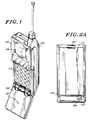
- a portable radiotelephone adapted to be used in a cellular radiotelephone system is shown in Fig. 1.
- the present invention may be employed in such a portable radiotelephone as well as in other miniature electronic equipment.
- the illustrated portable unit consists of two external portions, a body portion 102 and a flip element portion 104, in addition to a detachable battery 105.
- the drawing of Fig. 1 shows the flip element 104 in an "open" position such that a user of the portable unit may listen via earpiece 106 and may speak into a microphone 107.
- a telephone dial, or keypad, 110 consists of a plurality of buttons numbered one through zero, #, and *, in a familiar telephone arrangement.
- the keypad 110 also has additional function buttons such as "send", “end”, “on/off”, and other buttons associated with telephone number recall.
- the portable radiotelephone of Fig. 1 Since the portable radiotelephone of Fig. 1 is indeed portable, some source of electrical energy is necessary to power the electrical functions of this radiotelephone.
- the source of this electrical energy is a battery 105 which is typically implemented as a rechargeable electrochemical cell or cells. It is expected that the user will be able to either recharge the battery while the battery is attached to the radio or detach the battery from the radio and charge it separately.
- FIG. 2A the configuration of the detachable battery 105 can be apprehended in the condition where the battery 105 is detached from the portable radiotelephone of Fig. 1.
- An integral latch mechanism 201 is integrally molded on the battery housing.
- the battery housing consists of two halves which are permanently affixed together.
- the latch mechanism is molded into the inside half of the plastic housing.
- the latch mechanism 201 is pushed at the portion visible in Fig. 2A thereby causing a torsion beam (not shown) to rotate and cause a catch (not shown) to retract from a pocket 212 in the portable radiotelephone 102.
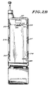
- the portable radiotelephone 102 in a rear elevation view with the battery removed, is shown in Fig. 2B.
- This action releases the battery from its locked position and enables the battery housing 105 to be removed from the portable radiotelephone 102.
- the mating surface of the portable radiotelephone 102 has a pocket or indented slot 212 which is so formed and positioned that it engages the catch portion of latch mechanism 201 when the battery housing 105 is located in its fully attached position. The battery housing is thereby locked in place.
- Guide rails 213 through 218 extend from a surface of the portable radiotelephone housing 102 and are disposed opposite similar guide rails on the battery housing 105.
- the guide rails of the battery housing 105 are captivated beneath guide rails 213 through 218 of the portable radiotelephone housing 102 when the battery housing 105 is in its operational (and locked) position.
- the operational position is, of course, when electrical contacts 225 have contacted mating contacts 325 (not visible) of the battery housing 105.
- Also visible in Fig. 2B are two molded flanges 220 and 221 which provide surfaces useable for preloading cantilevered springs enabling positive displacement of the battery housing 105 when it is unlocked.
- Lateral slots 233 and 235 in Fig. 2A on opposite sides of the battery housing assembly 105 are located in a position such that the battery alone or the battery and portable radiotelephone together may slide into a common battery charging unit and be properly oriented relative to the battery charging contacts 239.
- the surface of the battery housing 105 which mates to the portable radiotelephone of Fig. 2B is shown in the elevation view of the mating surface of Fig. 3.
- the latch mechanism 201 is seen in greater detail and it can be perceived how the catch 301 rotates about the torsion bar 303 when the button portion 305 is pressed by the user to remove the battery.
- An isometric view of the latch mechanism is shown in Fig. 6.
- Such a button pressing in a direction out of the plane of the page of Fig. 3 (and into indented area 227 of the portable radiotelephone housing 102) causes torsion bar 303 to rotate and move catch 301 into the plane of the page of Fig. 3. This motion disengages the catch 301 from slot 212 (shown in Fig.
- cantilevered spring fingers mechanically load the battery when the battery is in the inserted and locked position.
- spring fingers 320 and 321 on the battery housing are deflected downward by tabs 220 and 221 located on the portable radiotelephone housing 102.
- This downward deflection of spring fingers 320 and 321 provide a positive displacement of the battery when the latch mechanism 201 is activated by the user.
- the battery therefore, begins its disengagement when the user presses the latch mechanism and the battery slides downward enabling guide rails 307 through 312 to partially disengage from guide rails 213 through 218 on the portable radiotelephone housing.
- the guide rails are formed from raised protuberances on the inside surfaces of the lip edges which are raised slightly above the battery housing surface which faces the portable radiotelephone.
- FIG. 4 An exploded sectional view of the battery housing is shown in Fig. 4.
- a conventional set of electrochemical battery cells 401 may be sandwiched between and captivated by two plastic housing portions 403 and 405 which may be secured together to form an integral battery housing package.
- the latch mechanism 201 is molded as part of the plastic portion 405 and the cantilevered spring fingers 320 and 321 are molded as part of plastic portion 403 to minimize cost and reduce the volume required to implement the latching and positive displacement features of the present invention.
- three guide rails 310, 311 and 312 are located on one side of the battery housing and three guide rails (307, 308 and 309 not shown) are located on the other side of the battery housing.
- Figure 5 shows a cross-section of housing portion 403 which more clearly shows the spring fingers 320 and 321 as well as guide rails 310 and 307. It can be seen that lip edges 501 and 503, on opposite sides of the battery housing, are raised slightly above the plane of the surface of the battery housing which mates with the portable radiotelephone. In the cross-section shown in Fig. 5, the protuberances which form guide rails 310 and 307 are visible on the inside surface of the raised lips 501 and 503 respectively.
- each spring finger is a cantilevered trapezoidal shaped beam emanating at one end from the housing portion 403 and ending at the opposite end with a rectangular shaped target area 501 and 503 each of which contacts the flanges 220 or 221 of the portable radiotelephone housing.
- the housing portion 403 is molded from polycarbonate plastic or similar material and each spring finger is 0.13cm thick, and having a width at the point of attachment to the housing portion 403 of 0.51cm and narrowing to a width of 0.13cm.
- the length of the spring finger is 0.69cm from the point of attachment to the beginning of the rectangular target area.
- Each spring finger provides 8.34N (0.85Kg) of preload to the battery housing relative to the portable radiotelephone housing.
- a battery assembly having an integral latch mechanism, cantilevered spring fingers to provide positive displacement when the latch is disengaged, and reduced travel guide rails to provide short travel between the engaged and disengaged position of the battery housing on a portable radiotelephone has been shown and described.
Landscapes
- Engineering & Computer Science (AREA)
- Signal Processing (AREA)
- Electrochemistry (AREA)
- Life Sciences & Earth Sciences (AREA)
- Biophysics (AREA)
- Computer Hardware Design (AREA)
- Chemical & Material Sciences (AREA)
- Chemical Kinetics & Catalysis (AREA)
- Computer Networks & Wireless Communication (AREA)
- General Chemical & Material Sciences (AREA)
- Battery Mounting, Suspending (AREA)
- Telephone Set Structure (AREA)
- Electromechanical Clocks (AREA)
- Primary Cells (AREA)
- Lock And Its Accessories (AREA)
- Sealing Battery Cases Or Jackets (AREA)
- Hybrid Cells (AREA)
- Secondary Cells (AREA)
- Electric Clocks (AREA)
Claims (7)
- Boîtier de batterie (403, 405) pour un émetteur-récepteur portable (102) renfermant des éléments galvaniques électrochimiques (401) et ayant au moins une surface de fixation au moyen de laquelle l'ensemble de boîtier de batterie est fixé à une surface de l'émetteur-récepteur portable (102), le boîtier de batterie (403, 405) comprenant :un mécanisme de blocage (201) fixé au boîtier de batterie permettant d'immobiliser le boîtier de batterie sur l'émetteur-récepteur portable, le mécanisme de blocage comprenant un élément de levier à bouton poussoir (305) et un levier d'élément d'arrêt (301) ; etau moins deux rails guides (307-312) sur la surface de fixation du boîtier de batterie pour fixer, en le faisant glisser, le boîtier de batterie à des rails guides d'appariement (213-218) sur la surface de l'émetteur-récepteur portable, le boîtier de batterie étant caractérisé par :le mécanisme de blocage comprenant en outre un élément de potence allongé (303), soutenu à chaque extrémité pour former une barre de torsion, l'élément de levier à bouton poussoir (305) étant intégralement formé avec la barre de torsion (303) en placé perpendiculairement à la ligne médiane de ladite barre de torsion et entre les deux extrémités de ladite barre de torsion, et le levier d'élément d'arrêt (301) étant intégralement formé avec la barre de torsion et placé sensiblement perpendiculairement à la ligne médiane de ladite barre de torsion et entre les extrémités de ladite barre de torsion, la manipulation de l'élément de levier à bouton poussoir (305) faisant tourner ladite barre de torsion (303) afin de rétracter l'arrêt (301), dégageant ainsi le mécanisme de blocage pour rendre mobile le boîtier de batterie de l'émetteur-récepteur portable ; etun mécanisme de déplacement positif (320, 321) fixé au boîtier de batterie destiné à fournir un déplacement positif du boîtier de batterie lorsque le mécanisme de blocage est dégagé, le boîtier de batterie étant ainsi au moins partiellement dégagé, en le faisant glisser, de l'émetteur-récepteur portable.
- Boîtier de batterie selon la revendication 1, dans lequel les au moins deux rails guides (307-312) comprennent :des parties de rebord (501, 503) perpendiculaires au plan de la surface de fixation et situées sur deux bords opposés de la surface de fixation s'étendant au moins sur une partie de la longueur desdits bords opposés ; etau moins une protubérance allongée (307-312) s'étendant au delà des surfaces en vis à vis de chacune desdites parties de rebord (501, 503) et le long de chacune desdites parties de rebord parallèles au plan de la surface de fixation.
- Boîtier de batterie selon la revendication 1, ou 2 dans lequel ledit mécanisme de déplacement positif (320, 321) comprend un ressort presseur en porte à faux (320, 321) s'étendant au-delà de la surface de fixation selon une direction perpendiculaire au plan de la surface de fixation.
- Boîtier de batterie selon la revendication 1, 2 ou 3, dans lequel ledit élément de levier à bouton poussoir (305) est placé sensiblement au milieu des deux extrémités de ladite barre de torsion (303).
- Boîtier de batterie selon la revendication 1, 2, 3 ou 4, dans lequel le levier d'élément d'arrêt (301) est placé sensiblement au milieu des extrémités de ladite barre de torsion.
- Boîtier de batterie selon la revendication 1, 2 ou 3, dans lequel ledit levier d'élément d'arrêt (301) est placé en face dudit élément de levier à bouton poussoir (305).
- Boîtier de batterie selon l'une quelconque des revendications précédentes, dans lequel la surface de connexion du boîtier de batterie (403, 405) est une surface sensiblement plane.
Priority Applications (1)
| Application Number | Priority Date | Filing Date | Title |
|---|---|---|---|
| EP95109441A EP0691696B1 (fr) | 1988-11-04 | 1989-11-02 | Boítier de batterie avec verrou intégré et dispositif à déplacement positif |
Applications Claiming Priority (2)
| Application Number | Priority Date | Filing Date | Title |
|---|---|---|---|
| US07/269,853 US4904549A (en) | 1988-11-04 | 1988-11-04 | Battery housing with integral latch and positive displacement apparatus |
| US269853 | 1988-11-04 |
Related Child Applications (1)
| Application Number | Title | Priority Date | Filing Date |
|---|---|---|---|
| EP95109441.6 Division-Into | 1989-11-02 |
Publications (2)
| Publication Number | Publication Date |
|---|---|
| EP0367608A1 EP0367608A1 (fr) | 1990-05-09 |
| EP0367608B1 true EP0367608B1 (fr) | 1996-02-07 |
Family
ID=23028922
Family Applications (2)
| Application Number | Title | Priority Date | Filing Date |
|---|---|---|---|
| EP89311368A Expired - Lifetime EP0367608B1 (fr) | 1988-11-04 | 1989-11-02 | Boîtier de batterie avec verrou intégré et dispositif à déplacement positif |
| EP95109441A Expired - Lifetime EP0691696B1 (fr) | 1988-11-04 | 1989-11-02 | Boítier de batterie avec verrou intégré et dispositif à déplacement positif |
Family Applications After (1)
| Application Number | Title | Priority Date | Filing Date |
|---|---|---|---|
| EP95109441A Expired - Lifetime EP0691696B1 (fr) | 1988-11-04 | 1989-11-02 | Boítier de batterie avec verrou intégré et dispositif à déplacement positif |
Country Status (16)
| Country | Link |
|---|---|
| US (1) | US4904549A (fr) |
| EP (2) | EP0367608B1 (fr) |
| JP (1) | JPH06105607B2 (fr) |
| KR (1) | KR930001527B1 (fr) |
| AT (1) | ATE134072T1 (fr) |
| AU (1) | AU613546B2 (fr) |
| BR (1) | BR8907148A (fr) |
| CA (1) | CA2001020C (fr) |
| DE (1) | DE68925614D1 (fr) |
| DK (1) | DK154290A (fr) |
| FI (1) | FI903361A0 (fr) |
| GB (1) | GB2224595A (fr) |
| IE (2) | IE950965L (fr) |
| MX (1) | MX166682B (fr) |
| NO (1) | NO176498C (fr) |
| WO (1) | WO1990005385A1 (fr) |
Families Citing this family (86)
| Publication number | Priority date | Publication date | Assignee | Title |
|---|---|---|---|---|
| US5251105A (en) * | 1990-06-25 | 1993-10-05 | Kabushiki Kaisha Toshiba | Portable electronic apparatus having a battery pack with a mechanism for latching and an independent mechanism for temporarily preventing detachment |
| DE4192975C2 (de) * | 1990-11-30 | 1996-01-25 | Motorola Inc | Batteriegehäuseanordnung mit eingebauten Führungsschienen begrenzter Verschiebung sowie deren Verwendung |
| JP2673391B2 (ja) * | 1991-04-30 | 1997-11-05 | 松下電器産業株式会社 | 携帯電話機の電池パック保持装置 |
| JP2762168B2 (ja) * | 1991-05-09 | 1998-06-04 | モトローラ・インコーポレーテッド | トランシーバ用搭載アセンブリ |
| WO1992022146A1 (fr) * | 1991-06-03 | 1992-12-10 | Motorola, Inc. | Dispositif d'enclenchement de boitier de piles pour recepteur radio portatif |
| FR2680270A1 (fr) * | 1991-08-07 | 1993-02-12 | Alsthom Cge Alcatel | Boitier d'equipement electronique comprenant un dispositif de stockage de l'energie electrique. |
| US5122427A (en) * | 1991-08-09 | 1992-06-16 | Skil Corporation | Battery pack |
| USD352269S (en) | 1991-10-11 | 1994-11-08 | Alexander Manufacturing Company | Cellular telephone battery |
| USD350328S (en) | 1992-02-11 | 1994-09-06 | Alexander Manufacturing Company | Cellular telephone battery |
| USD349093S (en) | 1992-02-11 | 1994-07-26 | Alexander Manufacturing Company | Cellular telephone battery |
| US5213913A (en) * | 1992-02-21 | 1993-05-25 | Snap-On Tools Corporation | Latching arrangement for battery pack |
| US5242767A (en) * | 1992-06-22 | 1993-09-07 | Motorola, Inc. | Battery housing assembly with integral limited travel guide rails |
| US5244755A (en) * | 1992-10-23 | 1993-09-14 | Motorola, Inc. | Battery compartment door and latch having longitudinal snaps |
| JPH0773221B2 (ja) * | 1993-03-29 | 1995-08-02 | 日本電気株式会社 | 防水型無線通信機用筐体 |
| US5314763A (en) * | 1993-07-20 | 1994-05-24 | Motorola, Inc. | Battery latch |
| US5601942A (en) * | 1993-08-31 | 1997-02-11 | Vst Technologies, Inc. | Portable battery pack apparatus and method of fabrication thereof |
| US5366826A (en) * | 1993-09-20 | 1994-11-22 | Motorola, Inc. | Battery pack retention system and apparatus therefor |
| US5308716A (en) * | 1993-09-20 | 1994-05-03 | Motorola, Inc. | Battery pack retention apparatus |
| USD360184S (en) | 1994-05-31 | 1995-07-11 | Motorola, Inc. | Battery pack for a portable communication device |
| US5553675A (en) | 1994-06-10 | 1996-09-10 | Minnesota Mining And Manufacturing Company | Orthopedic surgical device |
| US5509704A (en) * | 1994-08-01 | 1996-04-23 | Motorola, Inc. | Cantilivered retention latch |
| GB2294357B (en) * | 1994-10-19 | 1997-03-26 | Nokia Mobile Phones Ltd | Battery pack |
| JP2674537B2 (ja) * | 1994-11-30 | 1997-11-12 | 日本電気株式会社 | 電子機器筐体 |
| USD366238S (en) | 1995-03-02 | 1996-01-16 | Zydek Stanley J | Portable radio battery eliminator |
| USD391224S (en) | 1995-03-10 | 1998-02-24 | Gemini Industries, Inc. | Battery pack |
| JP2856692B2 (ja) * | 1995-03-15 | 1999-02-10 | 埼玉日本電気株式会社 | 電子機器のロック構造 |
| US5850440A (en) * | 1995-03-15 | 1998-12-15 | Motorola, Inc. | Telephone handset mounting receptacle with card reader and method of positioning thereof |
| USD384059S (en) * | 1995-04-11 | 1997-09-23 | E.F. Johnson Company | Handheld two-way radio with hinged cover |
| US5678206A (en) * | 1995-04-12 | 1997-10-14 | E. F. Johnson Company | Keypad cover hinge |
| CA2174831C (fr) * | 1995-05-16 | 1999-09-07 | Ricky Latella | Appareil de prolongement de batterie et methode connexe |
| US5697070A (en) * | 1995-06-05 | 1997-12-09 | Lucent Technologies, Inc. | Battery pack for portable transceiver |
| US5604050A (en) * | 1995-06-13 | 1997-02-18 | Motorola Inc. | Latching mechanism and method of latching thereby |
| US5857148A (en) * | 1995-06-13 | 1999-01-05 | Motorola, Inc. | Portable electronic device and method for coupling power thereto |
| US5693431A (en) * | 1995-08-08 | 1997-12-02 | Selfcharge, Inc. | Rechargeable battery pack for mobile telephones |
| USD383433S (en) * | 1995-08-21 | 1997-09-09 | Motorola, Inc. | Battery eliminator housing for a portable radio |
| USD397109S (en) | 1995-08-25 | 1998-08-18 | E. F. Johnson Company | Handheld two-way radio with hinged cover |
| US5642404A (en) * | 1995-11-13 | 1997-06-24 | Hsu; Cheng-Ming | Clasp structure for cellular phone and battery set |
| USD379345S (en) * | 1995-12-08 | 1997-05-20 | Motorola, Inc. | Battery for a portable communication device |
| US5607792A (en) * | 1996-02-05 | 1997-03-04 | Motorola, Inc. | Battery latch |
| DE29607055U1 (de) * | 1996-04-18 | 1996-07-04 | VARTA Gerätebatterie GmbH, 30419 Hannover | Batteriegehäuse für tragbare Telefone |
| US5787361A (en) * | 1996-04-19 | 1998-07-28 | Chen; Sung-Chin | Coupling plate for mounting a battery pack onto a cellular phone |
| US5726383A (en) * | 1996-04-29 | 1998-03-10 | Geller; Uri | Telephone radiation shield |
| US5660945A (en) * | 1996-05-30 | 1997-08-26 | Motorola, Inc. | Battery having a latching mechanism with torsion plates |
| US5700042A (en) * | 1996-07-24 | 1997-12-23 | Ericsson, Inc. | Torsionally-biased latch arrangement |
| US6009168A (en) * | 1996-09-24 | 1999-12-28 | Motorola, Inc. | Holder for a portable electronic device |
| JP2000505935A (ja) * | 1996-12-13 | 2000-05-16 | コーニンクレッカ フィリップス エレクトロニクス エヌ ヴィ | バッテリ式装置及びバッテリユニット |
| US6754361B1 (en) * | 1997-04-17 | 2004-06-22 | 3M Innovative Properties Company | Ergonomic headset assembly |
| US5745579A (en) * | 1997-04-25 | 1998-04-28 | Motorola, Inc. | Cellular telephone security adapter and method |
| FI105521B (fi) * | 1997-06-17 | 2000-08-31 | Nokia Mobile Phones Ltd | Matkapuhelimen akku |
| US5909102A (en) * | 1998-01-21 | 1999-06-01 | Motorola, Inc. | Battery connection apparatus employing fixed latching members |
| USD410893S (en) * | 1998-03-12 | 1999-06-15 | Qualcomm Incorporated | Battery pack for a portable telephone |
| US6114625A (en) * | 1998-03-25 | 2000-09-05 | Lucent Technologies Inc. | Article comprising a fastener |
| US6157545A (en) * | 1998-05-14 | 2000-12-05 | Motorola, Inc. | Battery connection apparatus with end projections |
| JP3429681B2 (ja) | 1998-08-06 | 2003-07-22 | 松下電器産業株式会社 | 電池パック取り外し装置 |
| GB9821124D0 (en) * | 1998-09-29 | 1998-11-25 | Nokia Mobile Phones Ltd | Back cover for a mobile phone |
| US6054662A (en) * | 1999-04-26 | 2000-04-25 | Dell Usa L.P. | Torsion enhanced return device for electronic system push button |
| US6656626B1 (en) * | 1999-06-01 | 2003-12-02 | Porter-Cable Corporation | Cordless power tool battery release mechanism |
| EP1160895A1 (fr) * | 1999-12-17 | 2001-12-05 | Mitsubishi Denki Kabushiki Kaisha | Bloc-batterie et borne de communication mobile |
| US6660427B1 (en) * | 2000-11-06 | 2003-12-09 | Motorola Inc. | Latch assembly for portable electronic device |
| US20020076060A1 (en) * | 2000-12-19 | 2002-06-20 | Hall Ronald W. | Programmable headset and programming apparatus and method |
| KR100425094B1 (ko) * | 2001-07-02 | 2004-03-30 | 엘지전자 주식회사 | 휴대용 단말기의 배터리 팩 착탈 구조 |
| US20040161664A1 (en) * | 2001-08-14 | 2004-08-19 | Mitsubishi Denki Kabushiki Kaisha (A Corporation Of Japan) | Plate shaped battery pack and portable radio terminal |
| US6729413B2 (en) * | 2001-08-24 | 2004-05-04 | Black & Decker Inc. | Power tool with battery pack ejector |
| US7103392B2 (en) * | 2002-01-15 | 2006-09-05 | 3M Innovative Properties Company | Wireless intercom system |
| US6993292B2 (en) * | 2002-02-26 | 2006-01-31 | 3M Innovative Properties Company | Self-monitoring radio network |
| US7120388B2 (en) * | 2002-12-16 | 2006-10-10 | 3M Innovative Properties Company | Wireless intercom system and method of communicating using wireless intercom system |
| US7492273B2 (en) | 2003-03-10 | 2009-02-17 | Walter Kidde Portable Equipment, Inc. | Pivoting battery carrier and a life safety device incorporating the same |
| US20050084747A1 (en) * | 2003-10-17 | 2005-04-21 | Allen Aaron R. | Latching mechanism for electronic device and method of assembly |
| US7662507B2 (en) * | 2004-06-28 | 2010-02-16 | Honeywell International Inc. | HVAC controller battery tray |
| NZ534475A (en) * | 2004-08-02 | 2007-01-26 | Tait Electronics Ltd | Battery latching assembly of portable communication device, with contacts that slide apart to latch and are squeezed together to unlatch |
| RU2296391C2 (ru) * | 2004-09-21 | 2007-03-27 | Сони Компьютер Энтертайнмент Инк. | Батарейный блок и электронное устройство, в котором он используется |
| US7832652B2 (en) | 2005-01-31 | 2010-11-16 | Honeywell International Inc. | HVAC controller with side removable battery holder |
| CN101715277A (zh) * | 2008-10-06 | 2010-05-26 | 鸿富锦精密工业(深圳)有限公司 | 电子设备 |
| US9423805B2 (en) | 2013-02-12 | 2016-08-23 | Honeywell International Inc. | Wall-mounted controller with a removable portion |
| US9709295B2 (en) | 2013-03-15 | 2017-07-18 | Honeywell International, Inc. | Electronic device and methods |
| US20140324227A1 (en) | 2013-04-30 | 2014-10-30 | Honeywell International Inc. | Hvac controller having a fixed segment display with an interactive message center |
| US9823703B2 (en) | 2014-03-27 | 2017-11-21 | Google Inc. | Modules and connections for modules to couple to a computing device |
| CN106462215A (zh) | 2014-04-07 | 2017-02-22 | 谷歌公司 | 用于模块化移动电子设备的电力管理的系统和方法 |
| US10042402B2 (en) | 2014-04-07 | 2018-08-07 | Google Llc | Systems and methods for thermal management of a chassis-coupled modular mobile electronic device |
| US9717045B2 (en) | 2014-04-07 | 2017-07-25 | Google Inc. | Systems for enabling modular mobile electronic devices |
| US9621229B2 (en) * | 2014-04-07 | 2017-04-11 | Google, Inc. | Systems for enabling chassis-coupled modular mobile electronic devices |
| CN106462195A (zh) | 2014-08-22 | 2017-02-22 | 谷歌公司 | 用于模块化移动电子设备的模块对接的系统 |
| US9614942B2 (en) | 2014-08-22 | 2017-04-04 | Google Inc. | Systems and methods for tangible configuration of a modular mobile electronic device |
| US9674320B2 (en) | 2014-08-22 | 2017-06-06 | Google Inc. | Systems and methods for enabling radio-frequency communication of a modular mobile electronic device |
| USD940650S1 (en) | 2020-06-04 | 2022-01-11 | Honeywell International Inc. | Battery |
| EP3920317A1 (fr) | 2020-06-04 | 2021-12-08 | Honeywell International Inc. | Bloc-batterie amovible amélioré et mécanisme de verrouillage pour fixer un bloc-batterie amovible |
Family Cites Families (16)
| Publication number | Priority date | Publication date | Assignee | Title |
|---|---|---|---|---|
| CA834898A (en) * | 1966-04-04 | 1970-02-17 | H. Rush David | Combination apparatus cover and battery pack |
| US3728664A (en) * | 1971-12-21 | 1973-04-17 | Repco Inc | Battery latching mechanism |
| US3864172A (en) * | 1973-05-17 | 1975-02-04 | Rca Corp | Battery connecting assembly |
| DE2551663C3 (de) * | 1975-11-18 | 1979-04-26 | Licentia Patent-Verwaltungs-Gmbh, 6000 Frankfurt | Batteriekassette |
| JPS5811016Y2 (ja) * | 1977-05-13 | 1983-03-01 | オリンパス光学工業株式会社 | 電池箱取出し装置 |
| JPS6059638U (ja) * | 1983-09-29 | 1985-04-25 | 日本マランツ株式会社 | 携帯用無線機のアダプタ |
| DE8406521U1 (de) * | 1984-03-02 | 1984-07-05 | Hagenuk GmbH, 2300 Kiel | Schnurloses Telefon |
| JPS60230723A (ja) * | 1984-04-27 | 1985-11-16 | エルヴイン・ブランデンシユタイン | 無線電話幾 |
| US4578628A (en) * | 1985-01-04 | 1986-03-25 | Motorola Inc. | Portable battery powered electrical apparatus with improved battery pack protected against inadvertent short circuit of the battery terminals |
| JPS62272456A (ja) * | 1986-05-21 | 1987-11-26 | Hitachi Ltd | 蓄電池の脱着機構 |
| US4714439A (en) * | 1986-07-03 | 1987-12-22 | Motorola, Inc. | Electrical connector |
| US4680527A (en) * | 1986-08-06 | 1987-07-14 | Motorola, Inc. | Electrical battery including apparatus for current sensing |
| JPS6388749A (ja) * | 1986-10-01 | 1988-04-19 | Hitachi Ltd | バツテリ−パツク着脱機構 |
| JPS63119156A (ja) * | 1986-11-07 | 1988-05-23 | Canon Inc | 電池用コネクタ |
| GB2214008B (en) * | 1987-12-16 | 1992-02-12 | Technophone Ltd | Portable electrical device with rechargeable battery pack |
| US4912602A (en) | 1988-11-04 | 1990-03-27 | Motorola, Inc. | Mechanical fastening system for an electronic equipment housing |
-
1988
- 1988-11-04 US US07/269,853 patent/US4904549A/en not_active Expired - Fee Related
-
1989
- 1989-10-13 WO PCT/US1989/004819 patent/WO1990005385A1/fr not_active Ceased
- 1989-10-13 KR KR1019900701427A patent/KR930001527B1/ko not_active Expired - Fee Related
- 1989-10-13 FI FI903361A patent/FI903361A0/fi not_active IP Right Cessation
- 1989-10-13 BR BR898907148A patent/BR8907148A/pt not_active Application Discontinuation
- 1989-10-13 AU AU46201/89A patent/AU613546B2/en not_active Ceased
- 1989-10-19 CA CA002001020A patent/CA2001020C/fr not_active Expired - Fee Related
- 1989-10-27 MX MX018126A patent/MX166682B/es unknown
- 1989-11-02 EP EP89311368A patent/EP0367608B1/fr not_active Expired - Lifetime
- 1989-11-02 JP JP1285097A patent/JPH06105607B2/ja not_active Expired - Lifetime
- 1989-11-02 EP EP95109441A patent/EP0691696B1/fr not_active Expired - Lifetime
- 1989-11-02 DE DE68925614T patent/DE68925614D1/de not_active Expired - Lifetime
- 1989-11-02 AT AT89311368T patent/ATE134072T1/de not_active IP Right Cessation
- 1989-11-02 GB GB8924772A patent/GB2224595A/en not_active Withdrawn
- 1989-11-03 IE IE950965A patent/IE950965L/xx unknown
- 1989-11-03 IE IE354489A patent/IE81064B1/en not_active IP Right Cessation
-
1990
- 1990-06-26 DK DK154290A patent/DK154290A/da not_active IP Right Cessation
- 1990-07-02 NO NO902929A patent/NO176498C/no unknown
Non-Patent Citations (1)
| Title |
|---|
| PATENT ABSTRACT OF JAPAN, vol. 12, no. 324 (E-653)[3171], 02 September 1988 * |
Also Published As
| Publication number | Publication date |
|---|---|
| JPH02183962A (ja) | 1990-07-18 |
| KR900702585A (ko) | 1990-12-07 |
| KR930001527B1 (ko) | 1993-03-02 |
| FI903361A7 (fi) | 1990-07-04 |
| GB2224595A (en) | 1990-05-09 |
| GB8924772D0 (en) | 1989-12-20 |
| NO902929L (no) | 1990-07-02 |
| IE81064B1 (en) | 2000-01-12 |
| CA2001020A1 (fr) | 1990-05-04 |
| BR8907148A (pt) | 1991-02-26 |
| IE950965L (en) | 1990-05-04 |
| FI903361A0 (fi) | 1990-07-04 |
| IE893544L (en) | 1990-05-04 |
| WO1990005385A1 (fr) | 1990-05-17 |
| NO902929D0 (no) | 1990-07-02 |
| AU4620189A (en) | 1990-05-28 |
| NO176498C (no) | 1995-04-12 |
| AU613546B2 (en) | 1991-08-01 |
| EP0691696B1 (fr) | 1999-04-21 |
| JPH06105607B2 (ja) | 1994-12-21 |
| EP0367608A1 (fr) | 1990-05-09 |
| DE68925614D1 (de) | 1996-03-21 |
| MX166682B (es) | 1993-01-27 |
| US4904549A (en) | 1990-02-27 |
| DK154290D0 (da) | 1990-06-26 |
| DK154290A (da) | 1990-06-26 |
| NO176498B (no) | 1995-01-02 |
| ATE134072T1 (de) | 1996-02-15 |
| EP0691696A1 (fr) | 1996-01-10 |
| CA2001020C (fr) | 1993-11-09 |
Similar Documents
| Publication | Publication Date | Title |
|---|---|---|
| EP0691696B1 (fr) | Boítier de batterie avec verrou intégré et dispositif à déplacement positif | |
| EP1760997B1 (fr) | Mécanisme de verrouillage de batterie pour un appareil électronique | |
| US4912602A (en) | Mechanical fastening system for an electronic equipment housing | |
| US7796381B2 (en) | Battery cover latching assembly for portable electronic device | |
| EP0991246B1 (fr) | Couvercle arrière pour téléphone mobile | |
| US4828944A (en) | Thin battery-containing structure | |
| US7309253B2 (en) | Battery cover fixing mechanism and battery cover and housing assembly | |
| US8322760B2 (en) | Battery cover mechanism | |
| US7419742B2 (en) | Battery cover assembly for portable electronic device | |
| EP0716461B1 (fr) | Boítier de dispositif électronique ayant un compartement de stockage | |
| US20100062323A1 (en) | Battery cover mechanism | |
| US6975842B2 (en) | Mobile phone with battery latch | |
| US20120028095A1 (en) | Battery cover latching mechanism and electronic device using the same | |
| JP4048303B2 (ja) | 携帯端末機のバッテリカバーロッキング装置 | |
| US20090258287A1 (en) | Battery cover assembly for electronic device | |
| US7550226B2 (en) | Battery cover assembly for portable electronic device | |
| US7824793B2 (en) | Battery cover assembly for portable electronic device | |
| WO1992010004A1 (fr) | Ensemble logement de pile a rails de guidage de deplacement limite solidaires | |
| US6211648B1 (en) | Battery pack for portable computer | |
| US8165650B2 (en) | Portable electronic device | |
| US8673481B2 (en) | Battery system | |
| CN214797637U (zh) | 按压式开关结构及具有按压式开关结构的电子装置 | |
| CN212412787U (zh) | 充电端子的转换机构及应用其的无线充电设备 | |
| JPH06132672A (ja) | 電子機器 |
Legal Events
| Date | Code | Title | Description |
|---|---|---|---|
| PUAI | Public reference made under article 153(3) epc to a published international application that has entered the european phase |
Free format text: ORIGINAL CODE: 0009012 |
|
| AK | Designated contracting states |
Kind code of ref document: A1 Designated state(s): AT BE CH DE ES FR GB GR IT LI LU NL SE |
|
| 17P | Request for examination filed |
Effective date: 19901109 |
|
| 17Q | First examination report despatched |
Effective date: 19920206 |
|
| ITF | It: translation for a ep patent filed | ||
| GRAA | (expected) grant |
Free format text: ORIGINAL CODE: 0009210 |
|
| AK | Designated contracting states |
Kind code of ref document: B1 Designated state(s): AT BE CH DE ES FR GB GR IT LI LU NL SE |
|
| PG25 | Lapsed in a contracting state [announced via postgrant information from national office to epo] |
Ref country code: NL Free format text: LAPSE BECAUSE OF FAILURE TO SUBMIT A TRANSLATION OF THE DESCRIPTION OR TO PAY THE FEE WITHIN THE PRESCRIBED TIME-LIMIT Effective date: 19960207 Ref country code: LI Effective date: 19960207 Ref country code: GR Free format text: LAPSE BECAUSE OF FAILURE TO SUBMIT A TRANSLATION OF THE DESCRIPTION OR TO PAY THE FEE WITHIN THE PRESCRIBED TIME-LIMIT Effective date: 19960207 Ref country code: ES Free format text: THE PATENT HAS BEEN ANNULLED BY A DECISION OF A NATIONAL AUTHORITY Effective date: 19960207 Ref country code: CH Effective date: 19960207 Ref country code: BE Effective date: 19960207 Ref country code: AT Effective date: 19960207 |
|
| REF | Corresponds to: |
Ref document number: 134072 Country of ref document: AT Date of ref document: 19960215 Kind code of ref document: T |
|
| XX | Miscellaneous (additional remarks) |
Free format text: TEILANMELDUNG 95109441.6 EINGEREICHT AM 02/11/89. |
|
| ET | Fr: translation filed | ||
| REF | Corresponds to: |
Ref document number: 68925614 Country of ref document: DE Date of ref document: 19960321 |
|
| PG25 | Lapsed in a contracting state [announced via postgrant information from national office to epo] |
Ref country code: SE Effective date: 19960507 |
|
| PG25 | Lapsed in a contracting state [announced via postgrant information from national office to epo] |
Ref country code: DE Effective date: 19960508 |
|
| NLV1 | Nl: lapsed or annulled due to failure to fulfill the requirements of art. 29p and 29m of the patents act | ||
| REG | Reference to a national code |
Ref country code: CH Ref legal event code: PL |
|
| PG25 | Lapsed in a contracting state [announced via postgrant information from national office to epo] |
Ref country code: LU Free format text: LAPSE BECAUSE OF NON-PAYMENT OF DUE FEES Effective date: 19961130 |
|
| PLBE | No opposition filed within time limit |
Free format text: ORIGINAL CODE: 0009261 |
|
| STAA | Information on the status of an ep patent application or granted ep patent |
Free format text: STATUS: NO OPPOSITION FILED WITHIN TIME LIMIT |
|
| 26N | No opposition filed | ||
| REG | Reference to a national code |
Ref country code: GB Ref legal event code: IF02 |
|
| PGFP | Annual fee paid to national office [announced via postgrant information from national office to epo] |
Ref country code: GB Payment date: 20021002 Year of fee payment: 14 |
|
| PGFP | Annual fee paid to national office [announced via postgrant information from national office to epo] |
Ref country code: FR Payment date: 20021105 Year of fee payment: 14 |
|
| PG25 | Lapsed in a contracting state [announced via postgrant information from national office to epo] |
Ref country code: GB Free format text: LAPSE BECAUSE OF NON-PAYMENT OF DUE FEES Effective date: 20031102 |
|
| GBPC | Gb: european patent ceased through non-payment of renewal fee |
Effective date: 20031102 |
|
| PG25 | Lapsed in a contracting state [announced via postgrant information from national office to epo] |
Ref country code: FR Free format text: LAPSE BECAUSE OF NON-PAYMENT OF DUE FEES Effective date: 20040730 |
|
| REG | Reference to a national code |
Ref country code: FR Ref legal event code: ST |
|
| PG25 | Lapsed in a contracting state [announced via postgrant information from national office to epo] |
Ref country code: IT Free format text: LAPSE BECAUSE OF NON-PAYMENT OF DUE FEES;WARNING: LAPSES OF ITALIAN PATENTS WITH EFFECTIVE DATE BEFORE 2007 MAY HAVE OCCURRED AT ANY TIME BEFORE 2007. THE CORRECT EFFECTIVE DATE MAY BE DIFFERENT FROM THE ONE RECORDED. Effective date: 20051102 |
|
| P01 | Opt-out of the competence of the unified patent court (upc) registered |
Effective date: 20230520 |