EP0367628B1 - Bogenwendevorrichtung - Google Patents
Bogenwendevorrichtung Download PDFInfo
- Publication number
- EP0367628B1 EP0367628B1 EP89311431A EP89311431A EP0367628B1 EP 0367628 B1 EP0367628 B1 EP 0367628B1 EP 89311431 A EP89311431 A EP 89311431A EP 89311431 A EP89311431 A EP 89311431A EP 0367628 B1 EP0367628 B1 EP 0367628B1
- Authority
- EP
- European Patent Office
- Prior art keywords
- sheet
- belt
- pressing member
- roller
- pressing
- Prior art date
- Legal status (The legal status is an assumption and is not a legal conclusion. Google has not performed a legal analysis and makes no representation as to the accuracy of the status listed.)
- Expired - Lifetime
Links
- 230000002093 peripheral effect Effects 0.000 claims description 3
- 230000032258 transport Effects 0.000 description 8
- 230000015572 biosynthetic process Effects 0.000 description 2
- NIXOWILDQLNWCW-UHFFFAOYSA-N acrylic acid group Chemical group C(C=C)(=O)O NIXOWILDQLNWCW-UHFFFAOYSA-N 0.000 description 1
- 238000000151 deposition Methods 0.000 description 1
- 238000003384 imaging method Methods 0.000 description 1
- 239000011347 resin Substances 0.000 description 1
- 229920005989 resin Polymers 0.000 description 1
- 230000003068 static effect Effects 0.000 description 1
- 239000000126 substance Substances 0.000 description 1
Images




Classifications
-
- B—PERFORMING OPERATIONS; TRANSPORTING
- B65—CONVEYING; PACKING; STORING; HANDLING THIN OR FILAMENTARY MATERIAL
- B65H—HANDLING THIN OR FILAMENTARY MATERIAL, e.g. SHEETS, WEBS, CABLES
- B65H15/00—Overturning articles
Definitions
- the present invention relates to a device for turning a sheet of paper and, more specifically, to such a device usable for copying on both sides of a sheet of paper in a copying machine.
- An image formation apparatus such as a copying machine or a laser printer, capable of forming an image on both sides of a sheet of paper is commercially available.
- the sheet must be turned.
- a switchback type sheet turning device as shown in Fig. 6, for example, is commonly employed.
- the sheet turning apparatus is provided with a sheet transporting path 52, which makes a loop-shaped path with a printing unit 51 therein, to transport the sheet in the counterclockwise direction in the figure.
- the sheet is turned in the course of the circulation in the sheet transporting path 52 by rollers 53 which rotate in both the forward and reverse directions.
- the sheet is transported to the rollers 53 and moved by the rollers 53 until the tail portion of the sheet is nipped by the rollers 53. Then, the sheet is stopped once and transported with its original tail portion first by reverse rotation of the rollers 53. Since the sheet is turned by the transportation through which the original tail portion of the sheet goes first, the other side of the sheet is then formed with an original image when the sheet is transported through the printing unit 51 again. After that, the sheet with two images on both sides is discharged onto a sheet receiver 54 by the forward rotation of the rollers 53.
- the directions of the images on both sides of the sheet may be opposite to each other.
- a direction of the sheet transportation is the same as that of the images
- an image shown in a solid line in Fig. 7 is made on the first face of the sheet which is transported in the direction of an arrow A shown in Fig. 7.
- the rollers 53 turn the sheet so that the tail of the sheet goes first, the sheet is transported in a direction of an arrow B. Therefore, the direction of the image formed on a second face of the sheet is opposite to that of the image on the first face as can be seen from an illustration of a broken line in Fig. 7.
- image information stored in a memory can be read from the end of the information in, for example, a laser printer. In this manner, however, the control must be complicated.
- Transporting a sheet in a direction orthogonal to the transporting direction may come to turn the sheet as proposed in Japanese Examined Patent Publication No. 22787/1980 (US-A-4 136 862).
- a sheet having an image on one side is turned so that the first character train in the image goes first, that is, the sheet is turned in a direction opposite to the predetermined direction when the image is automatically copied on both sides of the sheet through a copying machine.
- the sheet turning device After the sheet goes through a fuser, the sheet is received by the sheet turning device. In the device, the sheet is transported in a direction orthogonal to the predetermined direction so that one side of the sheet goes first, and then the sheet is turned.
- the sheet is transported in the predetermined direction so that the original head of the sheet goes first, and then the sheet is turned.
- the sheet is transported in order to copy an image on the second face of the sheet.
- Fifth, the sheet having two images on both sides is received from the fuser by the sheet turning device and turned. After that, the sheet is transported to a sorter.
- a sheet inverting mechanism in which a sheet is inverted, in the course of its transport in a predetermined direction, by movement of the sheet in a direction orthogonal to the predetermined direction.
- the mechanism incorporates a plurality of belt conveyors which guide the sheet through a U-shaped path to turn the sheet over.
- the U-shaped path makes the mechanism undesirably bulky.
- the present invention is defined by claim 1.
- a preferred embodiment of the invention provides a sheet turning device in a sheet transporting path for receiving a sheet transported in a predetermined direction, turning the sheet and transporting the sheet in the direction, comprising a pair of rollers disposed on opposite sides of the sheet transporting path along the predetermined direction; a belt extending between the rollers for turning the sheet; means for stopping the sheet transported onto the lower inner surface of the belt; means for circulating the belt to transport the sheet kept on the lower inner surface of the belt in a direction orthogonal to the predetermined direction so that the sheet turns; a pressing member for stopping and pressing the sheet which is turning and moving, on the upper inner surface of the belt; and a sheet transporting roller for pressing the sheet against the pressing member to transport the sheet pressed by the pressing member in the predetermined direction in spite of pressing the sheet against the upper inner surface by the pressing member.
- the transported sheet is moved upward by the inner surface of the belt in a direction orthogonal to the predetermined direction so that it is turned.
- the turning of the sheet is carried out not in a direction identical with the predetermined direction but in a direction orthogonal to the predetermined direction, so that the sheet can be turned without changing the head and tail of the sheet.
- the device When the sheet is turned, the sheet moves upward on the inner surface of the sheet turning belt, so that the sheet must be kept on the upper inner surface of the belt.
- the device has a retaining means such as the aforementioned pressing member for pressing the upper inner surface of the sheet turning belt. Since the pressing member is placed inside the sheet turning belt, the device can be miniaturized.
- Fig. 5 is a schematic view showing a constitution of a main portion of a laser printer L having a sheet turning device which is an embodiment according to the present invention.
- the laser printer L comprises a printing unit 1, a sheet circulating unit 2, a sheet turning unit (a sheet turning device) 3, a sheet tray 4 and a sheet receiver 5.
- the printing unit 1 includes a photoconductive drum 11 made of a photosensitive substance and a processing unit provided on the peripheral portion of the drum 11 for producing an image.
- the printing unit 1 produces an image on the upper side of a sheet fed from the sheet tray 4 or the sheet circulating unit 2.
- An electrifying device 12 for uniformly establishing static electric charge on the surface of the photoconductive drum 11, a laser unit 13 for directing light to the charged photoconductive drum 11 to make a latent image thereon, a developing unit 14 for depositing toner on the latent image and making it visible by development, a transferring unit 15 for transferring the image of toner to paper and a cleaner 17 for eliminating the toner remaining on the photoconductive drum 11 are disposed in that order, surrounding the photoconductive drum 11, to produce an image with toner on a sheet of paper.
- the image of toner is fused on the sheet by a fuser 16, and then the sheet is transported to the sheet circulating unit 2.
- the sheet circulating unit 2 receives the sheet from the fuser 16, transports the sheet in the counterclockwise direction so as to pass it under the printing unit 1 and further transports it through the sheet turning device 3 to the printing unit 1 again.
- the sheet circulating unit 2 is provided with a flap 21 close to the fuser 16.
- the flap 21 sorts sheets fed from the fuser 16 upward and downward by virtue of a solenoid 21a and a return spring 21b. A sheet guided upward is transported to the sheet receiver 5, and a sheet guided downward is transported to the printing unit 1 again through the sheet turning device 3.
- the sheet turning device turns the sheet.
- the sheet turning device has a microswitch 22 serving as a sheet stopper and a feeding roller 23 in its inlet.
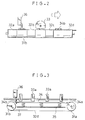
- Figs. 1 to 3 are views showing a constitution of the sheet turning device 3: Fig. 1 is a plan view, Fig. 2 is an elevational view and Fig. 3 is a side view seen from the right.
- Arrow C in those figures denotes a predetermined direction in which the sheet circulating unit 3 transports a sheet.
- Reference character D in Fig. 1 denotes a sheet transporting path in the sheet circulating unit 3.
- a pair of rollers 31a, 31b are disposed on opposite sides of the sheet transporting path D in a direction corresponding to the predetermined direction C.
- the rollers 31a, 31b are connected to a driving system (not shown), such as a driving shaft of a photoconductive drum serving as belt driving means and rotated in the counterclockwise direction in Fig. 3.
- Belts, or specifically four sheet turning belts, 32a to 32d extend between the rollers 31a, 31b at an interval to each other. These belts 32a to 32d are rotated in the direction orthogonal to the predetermined direction C (namely, in the counterclockwise direction in Fig. 3) by the rotation of the rollers 31a, 31b.
- a sheet transporting roller 33 is positioned between the belts 32b, 32c.
- the sheet transporting roller 33 (referred to simply as “transporting roller 33" below), which is rotated by a driving system not shown in the drawings, transports the sheet whose head and tail are reversed in the predetermined direction C.
- a presser 34 is mounted close to and inside the upper extension of each of the belts 32a to 32d between the rollers 31a, 31b.
- the presser 34 may be a plate of resin such as acrylic and is pressed against the upper extension of each of the belts 32a to 32d from the inside by pressing members including springs 35.
- the sheet is sent in a space between the presser 34 and the belts 32a to 32d by the rotation of the belts 32a to 32d.
- the transporting roller 33 rotates in contact with the upper surface of the presser 34 when the sheet is transported.
- the transporting roller 33 has semicircular pickup rollers 33a.
- the transporting roller 33 does not come in contact with the presser 34, because each of the pickup rollers 33a is positioned with a straight part of its peripheral surface being opposite to the presser 34.
- the transporting roller 33 rotates, and a arc portion each of the pickup rollers 33a comes in contact with the presser 34.
- the sheet on the presser 34 is transported in the predetermined direction C by friction force against the pressing force that the presser 34 produces by pressing the upper inside extension of each of the belts 32a to 32d.
- An end 34a of the presser 34 is slightly bent down close to the roller 31a which comes in contact with the sheet and serves as a paper guide. Because of the end 34a, the sheet transported from the sheet turning device along the inner surface of each of the belts 32a to 32d is assuredly guided to a space between the presser 34 and the belts 32a to 32d without deviating from the presser 34.
- an end 34b of the presser 34 is bent up close to the roller 31b which does not come in contact with the sheet and serves as a guard. The end 34b stops the sheet sent through the space between the presser 34 and the belts 32a to 32d.
- a microswitch 36 is mounted close to the end 34b to sense the sheet kept at the end 34b.
- a paper guide 37 is held slightly above the inner surface of the lower extension of each of the belts 32a to 32d along the predetermined direction C.
- the paper guide 37 prevents the belts 32a to 32d extending orthogonal to the predetermined direction C from catching the sheet from the sheet circulating unit 2. The sheet is sent along the paper guide 37.
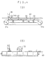
- Figs. 4(A) to 4(E) are views showing sequential steps of the operation of the sheet turning device. According to convenience of explanation, Figs. 4(A) and 4(E) are elevational views, and Figs. 4(B) to 4(D) are side views.
- a sheet 40 printed with an image on one side is fed to the sheet turning device 3.
- the sheet 40 is sent in a direction corresponding to an arrow C along the paper guide 37 and is stopped on the inner surface of the lower extension of each of the belts 32a to 32d in accordance with a stop of the feeding roller 23 a predetermined period of time after the microswitch 22 turns off (the tail of the sheet passes the microswitch 22).
- the sheet 40 has its face having the image positioned on the surface of each of the belts 32a to 32d (namely, the sheet 40 lies on the face having the image) (see Fig. 4(A)).
- the sheet 40 begins to move along the inner surface of the extension of each of the belts 32a to 32d (Fig. 4(B)) and is sent to the space between the presser 34 and the belts 32a to 32d (Fig. 4(C)).
- the transportation of the sheet 40 is stopped by the end portion 34b of the presser 34, and simultaneously the microswitch 36 turns on (Fig. 4(D)).
- the rollers 31a, 31b are stopped.
- the sheet 40 has the face having the image positioned on the surface of the belts 32a to 32d, namely, the sheet 40 is turned compared to the original state shown in Fig. 4(A).
- the feeding roller 33 rotates to move the sheet 40 on the presser 34 in the predetermined direction C (Fig. 4(E)) to the printing unit 1 so that the sheet 40 lies on the face having no image therein.
- the sheet turning device 3 can turn a sheet in the above mentioned manner.
- the head and tail of the sheet is kept unchanged, and therefore there is no need to rearrange an original image upside down.
- the sheet turning device 3 can be advantageously miniaturized because it does not require many trays and sheets are transported along and inside the sheet turning belts unlike a device disclosed in Japanese Examined Patent Publication No. 22787/1980. (US-A-4 136 862)
- the sheet turning device 3 turns a sheet without changing the head and tail of the sheet with regard to a predetermined direction in which sheets are transported, and therefore there is no possibility that an image is produced upside down when the sheet turning device 3 is employed in an imaging machine or the like. Additionally, there is another advantage that the sheet turning device can be miniaturized because the sheet is turned by transporting it along the inner surface of the belts extending between the rollers.
Landscapes
- Engineering & Computer Science (AREA)
- Mechanical Engineering (AREA)
- Registering Or Overturning Sheets (AREA)
- Counters In Electrophotography And Two-Sided Copying (AREA)
Claims (10)
- Bogenwendevorrichtung (3) zum Wenden eines Bogens (40), der in bestimmter Richtung in einem Bogentransportweg transportiert wird, ohne die Führungskante zu wechseln, mit:
mindestens einem Endlosriemen (32), der sich in einer langgestreckten Schleife quer zum Transportweg erstreckt;
einer Antriebseinrichtung (31a, 31b) für den Endlosriemen;
dadurch gekennzeichnet, daß
der Endlosriemen (32) so angeordnet ist, daß er einen Bogen aufseiner Innenseite erfaßt und von einer ersten Position im unteren, Inneren Teil der langgestreckten Schleife in eine zweite Position im oberen, inneren Teil der Schleife transportiert, wobei der Bogen gewendet wird;
eine Einrichtung (34) zum Festhalten des Bogens auf dem Endlosriemen in der zweiten Position vorhanden ist; und daß
eine Einrichtung (33) zum Ablösen des Bogens vom Endlosriemen in der zweiten Position vorhanden ist. - Bogenwendevorrichtung nach Anspruch 1, dadurch gekennzeichnet, daß
die Antriebseinrichtung ein Paar von Walzen (31a, 31b) aufweist die an sich gegenüberliegenden Seiten des Bogentransportwegs entlang der bestimmten Richtung angeordnet sind;
die Festhalteeinrichtung ein Andruckteil (34) zum Stoppen und Andrücken des Bogens auf die Riemenoberfläche in der zweiten Position aufweist; und daß
die Ablöseeinrichtung eine Bogentransportwalze (33) zum Andrücken des Bogens gegen das Andruckteil (34) aufweist, um den durch das Andruckteil gedrückten Bogen in der bestimmten Richtung zu transportieren, obwohl der Bogen durch das Andruckteil gegen die Riemenoberfläche gedrückt wird. - Vorrichtung nach Anspruch 1 oder 2, dadurch gekennzeichnet, daß der Endlosriemen (32) durch eine Mehrzahl von einzelnen schmalen Riemen (32a - 32d) gebildet ist.
- Vorrichtung nach Anspruch 2 und 3, dadurch gekennzeichnet, daß die einzelnen Riemen (32a - 32d) so angeordnet sind, daß die Bogentransportwalze (33) über einen Zwischenraum mit dem Andruckteil (34) in Kontakt kommen kann.
- Vorrichtung nach Anspruch 2, dadurch gekennzeichnet, daß das Andruckteil eine Platte (34) und eine die Platte nach oben drückende Feder (35) aufweist.
- Vorrichtung nach Anspruch 1 oder 2, mit einer Einrichtung (22,23) zum Stoppen eines durch den Endlosriemen vom Bogentransportweg empfangenen Bogens in der ersten Position.
- Vorrichtung nach Anspruch 2, dadurch gekennzeichnet, daß das Walzenpaar eine Walze (31a), die in Kontakt mit dem sich entlang der langgestreckten Schleife bewegenden Bogen kommt, wenn der Riemen sich dreht und eine Walze (31b), die nicht den Bogen berührt, aufweist, und daß das Andruckteil (34) eine Führung (34a) aufweist, die an dem Ende nahe bei der Kontaktwalze (31a) leicht nach unten gekrümmt ist, um den sich bewegenden Bogen zu einem Zwischenraum zwischen dem Andruckteil und dem Endlosriemen in die zweite Position des Bogens zu führen.
- Vorrichtung nach Anspruch 2, dadurch gekennzeichnet, daß das Walzenpaar eine Walze (31a), die in Kontakt mit dem sich entlang der langgestreckten Schleife bewegenden Bogen kommt, wenn der Endlosriemen sich dreht und eine Walze (31b), die nicht den Bogen berührt, aufweist, und daß das Andruckteil (34) einen Anschlag (34b) aufweist, der an dem Ende nahe bei der nicht in Kontakt stehenden Walze (31b) nach oben gebogen ist, um den Bogen an seiner Stirnseite zwischen dem Andruckteil und dem Endlosriemen in der zweiten Position des Endlosriemens zu stoppen.
- Vorrichtung nach Anspruch 2, dadurch gekennzeichnet, daß die Bogentransportwalze eine Aufnahmewalze (33a) mit einen halbkreisförmigen Querschnitt aufweist, wobei ihre ebene Mantelfläche dem Andruckteil (34) gegenübersteht wenn sich der Endlosriemen dreht.
- Vorrichtung nach einem der vorstehenden Ansprüche, mit einer über der unteren Innenfläche des Endlosriemens angeordneten Papierführungsplatte (37), um zu vermeiden, daß der Endlosriemen einen Bogen ergreift, der in die bestimmte Richtung transportiert wird.
Applications Claiming Priority (2)
| Application Number | Priority Date | Filing Date | Title |
|---|---|---|---|
| JP279145/88 | 1988-11-04 | ||
| JP63279145A JPH07122758B2 (ja) | 1988-11-04 | 1988-11-04 | 用紙反転装置 |
Publications (3)
| Publication Number | Publication Date |
|---|---|
| EP0367628A2 EP0367628A2 (de) | 1990-05-09 |
| EP0367628A3 EP0367628A3 (en) | 1990-09-12 |
| EP0367628B1 true EP0367628B1 (de) | 1994-05-04 |
Family
ID=17607068
Family Applications (1)
| Application Number | Title | Priority Date | Filing Date |
|---|---|---|---|
| EP89311431A Expired - Lifetime EP0367628B1 (de) | 1988-11-04 | 1989-11-03 | Bogenwendevorrichtung |
Country Status (4)
| Country | Link |
|---|---|
| US (1) | US4988088A (de) |
| EP (1) | EP0367628B1 (de) |
| JP (1) | JPH07122758B2 (de) |
| DE (1) | DE68915117T2 (de) |
Families Citing this family (6)
| Publication number | Priority date | Publication date | Assignee | Title |
|---|---|---|---|---|
| US5052678A (en) * | 1989-09-13 | 1991-10-01 | Xerox Corporation | Duplex feeder with side shifting inversion |
| DE60104669D1 (de) * | 2000-04-14 | 2004-09-09 | Teknologi & Produkt Udvikling | Vorrichtung zum invertieren und ausgeben von blättern von einem drucker für grossformatiges papier |
| SE525674C2 (sv) * | 2003-08-13 | 2005-04-05 | Somitrack Ab | Förfarande och anordning för kontroll av utskjutningar för trycksidor |
| US20070132179A1 (en) * | 2005-12-14 | 2007-06-14 | Pitney Bowes Incorporated | Method and device for aligning sheets in a transport module |
| US8944431B1 (en) | 2013-07-22 | 2015-02-03 | Eastman Kodak Company | Compact inverter for cut sheet media |
| CN114873322B (zh) * | 2022-05-13 | 2023-07-11 | 江苏理工学院 | 一种自动辅助翻纸装置 |
Family Cites Families (8)
| Publication number | Priority date | Publication date | Assignee | Title |
|---|---|---|---|---|
| US4019435A (en) * | 1975-08-21 | 1977-04-26 | Addressograph Multigraph Corporation | Sheet inverting |
| US4027870A (en) * | 1976-10-04 | 1977-06-07 | Terminal Data Corporation | End for end document inverter |
| US4136862A (en) * | 1977-04-13 | 1979-01-30 | International Business Machines Corporation | Paper orientation for duplexing and collating |
| US4155440A (en) * | 1977-07-05 | 1979-05-22 | Pitney-Bowes, Inc. | Document turning station |
| JPS5457759A (en) * | 1977-10-17 | 1979-05-09 | Ricoh Co Ltd | Paper feeder of duplicator, printing machine, etc. |
| JPS5522787A (en) * | 1979-06-18 | 1980-02-18 | Canon Inc | Flashing device |
| JPS60247655A (ja) * | 1984-05-23 | 1985-12-07 | Toshiba Corp | 画像形成装置 |
| JPS63134437A (ja) * | 1986-11-26 | 1988-06-07 | Seikosha Co Ltd | 両面記録装置 |
-
1988
- 1988-11-04 JP JP63279145A patent/JPH07122758B2/ja not_active Expired - Fee Related
-
1989
- 1989-11-01 US US07/430,148 patent/US4988088A/en not_active Expired - Lifetime
- 1989-11-03 DE DE68915117T patent/DE68915117T2/de not_active Expired - Fee Related
- 1989-11-03 EP EP89311431A patent/EP0367628B1/de not_active Expired - Lifetime
Also Published As
| Publication number | Publication date |
|---|---|
| EP0367628A2 (de) | 1990-05-09 |
| US4988088A (en) | 1991-01-29 |
| DE68915117T2 (de) | 1994-10-13 |
| JPH02125268A (ja) | 1990-05-14 |
| JPH07122758B2 (ja) | 1995-12-25 |
| EP0367628A3 (en) | 1990-09-12 |
| DE68915117D1 (de) | 1994-06-09 |
Similar Documents
| Publication | Publication Date | Title |
|---|---|---|
| JPH02305058A (ja) | プリンター装置 | |
| US5042791A (en) | Short edge feed duplex with side shifting inverter | |
| US4508444A (en) | Multimode document handling apparatus and reproducing apparatus containing same | |
| US4432541A (en) | Recirculating document feed apparatus and method for aligning documents therein | |
| US5052678A (en) | Duplex feeder with side shifting inversion | |
| US4712786A (en) | Copy sheet offsetting device | |
| EP0367628B1 (de) | Bogenwendevorrichtung | |
| US5090675A (en) | Apparatus for automatically transporting sheets of orginal | |
| US5048817A (en) | Dynamic edge guide for side registration systems | |
| EP0378005B1 (de) | Kopieblatt-Umlenkvorrichtung | |
| JPH0672641A (ja) | シート収集及び送り出し装置 | |
| US5549291A (en) | Printer with multiple-sized sheets duplex tray assembly | |
| US20030133732A1 (en) | Stall roll registration system and method employing a ball-on-belt input transport | |
| US5606722A (en) | Internal electrical contact for magnetic development rolls | |
| US6941104B2 (en) | Carrying apparatus and image forming apparatus | |
| JP2638958B2 (ja) | 用紙搬送装置 | |
| JP2509230B2 (ja) | シ−ト取扱装置 | |
| JP2899423B2 (ja) | 記録装置 | |
| JP2001097622A (ja) | 画像形成装置 | |
| JPH0739902Y2 (ja) | 用紙搬送装置 | |
| JP3002086B2 (ja) | シート搬送装置及び原稿自動給送装置及び画像形成装置 | |
| JP2000118829A (ja) | 紙葉類搬送装置 | |
| JP2874791B2 (ja) | 原稿搬送装置 | |
| JPH04350880A (ja) | 電子写真装置 | |
| JPH10120239A (ja) | 記録媒体搬送装置 |
Legal Events
| Date | Code | Title | Description |
|---|---|---|---|
| PUAI | Public reference made under article 153(3) epc to a published international application that has entered the european phase |
Free format text: ORIGINAL CODE: 0009012 |
|
| AK | Designated contracting states |
Kind code of ref document: A2 Designated state(s): DE GB |
|
| PUAL | Search report despatched |
Free format text: ORIGINAL CODE: 0009013 |
|
| AK | Designated contracting states |
Kind code of ref document: A3 Designated state(s): DE GB |
|
| 17P | Request for examination filed |
Effective date: 19901010 |
|
| 17Q | First examination report despatched |
Effective date: 19921109 |
|
| GRAA | (expected) grant |
Free format text: ORIGINAL CODE: 0009210 |
|
| AK | Designated contracting states |
Kind code of ref document: B1 Designated state(s): DE GB |
|
| REF | Corresponds to: |
Ref document number: 68915117 Country of ref document: DE Date of ref document: 19940609 |
|
| PLBE | No opposition filed within time limit |
Free format text: ORIGINAL CODE: 0009261 |
|
| STAA | Information on the status of an ep patent application or granted ep patent |
Free format text: STATUS: NO OPPOSITION FILED WITHIN TIME LIMIT |
|
| 26N | No opposition filed | ||
| REG | Reference to a national code |
Ref country code: GB Ref legal event code: IF02 |
|
| PGFP | Annual fee paid to national office [announced via postgrant information from national office to epo] |
Ref country code: DE Payment date: 20041028 Year of fee payment: 16 |
|
| PGFP | Annual fee paid to national office [announced via postgrant information from national office to epo] |
Ref country code: GB Payment date: 20041104 Year of fee payment: 16 |
|
| PG25 | Lapsed in a contracting state [announced via postgrant information from national office to epo] |
Ref country code: GB Free format text: LAPSE BECAUSE OF NON-PAYMENT OF DUE FEES Effective date: 20051103 |
|
| PG25 | Lapsed in a contracting state [announced via postgrant information from national office to epo] |
Ref country code: DE Free format text: LAPSE BECAUSE OF NON-PAYMENT OF DUE FEES Effective date: 20060601 |
|
| GBPC | Gb: european patent ceased through non-payment of renewal fee |
Effective date: 20051103 |