EP0367642B1 - Verfahren und Vorrichtung zum Verformen von Blech, insbesondere zum Realisieren einer Lochmaske für Kathodenstrahlröhren gemäss dem Verfahren - Google Patents
Verfahren und Vorrichtung zum Verformen von Blech, insbesondere zum Realisieren einer Lochmaske für Kathodenstrahlröhren gemäss dem Verfahren Download PDFInfo
- Publication number
- EP0367642B1 EP0367642B1 EP89402656A EP89402656A EP0367642B1 EP 0367642 B1 EP0367642 B1 EP 0367642B1 EP 89402656 A EP89402656 A EP 89402656A EP 89402656 A EP89402656 A EP 89402656A EP 0367642 B1 EP0367642 B1 EP 0367642B1
- Authority
- EP
- European Patent Office
- Prior art keywords
- sheet
- punch
- die
- metal blank
- clamping member
- Prior art date
- Legal status (The legal status is an assumption and is not a legal conclusion. Google has not performed a legal analysis and makes no representation as to the accuracy of the status listed.)
- Expired - Lifetime
Links
- 239000002184 metal Substances 0.000 title claims description 25
- 238000000034 method Methods 0.000 title claims description 11
- 238000007493 shaping process Methods 0.000 title description 3
- 230000002093 peripheral effect Effects 0.000 claims description 43
- 238000006073 displacement reaction Methods 0.000 claims description 5
- 239000000463 material Substances 0.000 claims description 4
- 230000007935 neutral effect Effects 0.000 claims description 4
- 239000011159 matrix material Substances 0.000 description 12
- 239000000835 fiber Substances 0.000 description 9
- 230000000694 effects Effects 0.000 description 7
- 230000006835 compression Effects 0.000 description 3
- 238000007906 compression Methods 0.000 description 3
- 208000035388 Ring chromosome 22 syndrome Diseases 0.000 description 2
- 230000000295 complement effect Effects 0.000 description 2
- 239000002131 composite material Substances 0.000 description 2
- 238000010438 heat treatment Methods 0.000 description 2
- 230000000630 rising effect Effects 0.000 description 2
- 230000015572 biosynthetic process Effects 0.000 description 1
- 238000007796 conventional method Methods 0.000 description 1
- 238000001816 cooling Methods 0.000 description 1
- 230000001939 inductive effect Effects 0.000 description 1
- 238000005554 pickling Methods 0.000 description 1
- 230000000284 resting effect Effects 0.000 description 1
- 238000000926 separation method Methods 0.000 description 1
- 238000005482 strain hardening Methods 0.000 description 1
- 239000000126 substance Substances 0.000 description 1
- 230000000930 thermomechanical effect Effects 0.000 description 1
Images

Classifications
-
- H—ELECTRICITY
- H01—ELECTRIC ELEMENTS
- H01J—ELECTRIC DISCHARGE TUBES OR DISCHARGE LAMPS
- H01J9/00—Apparatus or processes specially adapted for the manufacture, installation, removal, maintenance of electric discharge tubes, discharge lamps, or parts thereof; Recovery of material from discharge tubes or lamps
- H01J9/20—Manufacture of screens on or from which an image or pattern is formed, picked up, converted or stored; Applying coatings to the vessel
-
- B—PERFORMING OPERATIONS; TRANSPORTING
- B21—MECHANICAL METAL-WORKING WITHOUT ESSENTIALLY REMOVING MATERIAL; PUNCHING METAL
- B21D—WORKING OR PROCESSING OF SHEET METAL OR METAL TUBES, RODS OR PROFILES WITHOUT ESSENTIALLY REMOVING MATERIAL; PUNCHING METAL
- B21D22/00—Shaping without cutting, by stamping, spinning, or deep-drawing
- B21D22/10—Stamping using yieldable or resilient pads
-
- H—ELECTRICITY
- H01—ELECTRIC ELEMENTS
- H01J—ELECTRIC DISCHARGE TUBES OR DISCHARGE LAMPS
- H01J9/00—Apparatus or processes specially adapted for the manufacture, installation, removal, maintenance of electric discharge tubes, discharge lamps, or parts thereof; Recovery of material from discharge tubes or lamps
- H01J9/02—Manufacture of electrodes or electrode systems
- H01J9/14—Manufacture of electrodes or electrode systems of non-emitting electrodes
- H01J9/142—Manufacture of electrodes or electrode systems of non-emitting electrodes of shadow-masks for colour television tubes
-
- H—ELECTRICITY
- H01—ELECTRIC ELEMENTS
- H01J—ELECTRIC DISCHARGE TUBES OR DISCHARGE LAMPS
- H01J2229/00—Details of cathode ray tubes or electron beam tubes
- H01J2229/07—Shadow masks
- H01J2229/0722—Frame
Definitions
- the subject of the present invention is a method and a device for forming a sheet blank, in particular for producing a cathode ray tube mask.
- the sheet blank is held at its peripheral part and one acts on the central part of the latter under the action of lowering or raising a punch which gradually forms the blank by falling off the peripheral edge.
- the peripheral part undergoes a shrinking given the decrease in the perimeter from the outside, while the central part is expanding.
- One is therefore led to avoid the formation of folds to increase the pressure under the blank holder, which leads to increasing the tensile force to be exerted on the central part as a function of the peripheral forces and consequently the elongation of the metal in this part.
- the masks for cathode ray tubes are produced from an extra-thin sheet metal blank comprising at its central part a network of micro-perforations which have to meet extremely severe requirements regarding the positioning and shape of the perforations.
- the masks for cathode ray tubes have been produced by conventional drawing of the central part with punch and die, in heating the peripheral part of the sheet blank to a suitable temperature to make the latter more ductile and therefore favor its deformation by limiting the tensile force in the central part.
- heating has the disadvantage of causing the appearance of oxides and requiring pickling and cooling in the central part of the sheet blank.
- the object of the invention is to provide a cold-working method of forming a sheet blank and producing, in a single operation, the curve of the central part and the falling or lifting of the peripheral zone of the sheet blank. , without deforming the network of perforations, while avoiding the drawbacks of the calorific contribution mentioned above.
- the energy of the peripheral deformation is therefore no longer of thermo-mechanical origin, but of mechanical origin.
- the invention also relates to a device for forming a sheet blank, in particular for producing a cathode-ray tube mask, on a press comprising a die and a punch supported by an upper sole by means of an intermediate sole.
- a member for clamping the periphery of the sheet metal blank characterized in that the die and the punch are made of a deformable material and in that it comprises means for exerting in localized areas a mechanical action on the member clamping by bringing in the lateral direction the opposite elements of the clamping member, means of vertical displacement of the clamping member relative to the punch-die assembly and a deformable peripheral blade to control buckling and unwind the peripheral part of the sheet blank along the side walls of the punch or die in order to obtain the final fallen edge.
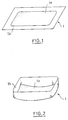
- Fig. 1 represents a sheet blank 1 of very small thickness from which a cathode-ray tube mask is produced.
- This sheet blank has a central part provided with a network of micro-perforations and a peripheral part 1b not perforated.
- the mask produced after forming therefore has its central part 1a corresponding to the network of curved micro-perforations and its peripheral edge 1b raised, as appears in FIG. 2.
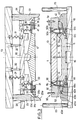
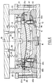
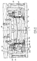
- the forming device shown in FIG. 3 for producing a cathode-ray tube mask comprises a lower sole 10 on which a base of matrix 11 rests. This base of matrix 11 is provided at its central part with an imprint 12.
- the forming device Above the bottom of the matrix 11, the forming device comprises a deformable matrix 13 which rests on the bottom of the matrix 11 by its peripheral part 14.
- the matrix 13 is connected by a rod 15 to a locking system 16 constituted for example by a jack.
- the forming device also comprises a deformable punch 17 supported by an intermediate sole 18 which is itself supported by an upper sole 19 by means of balusters 20 slidably mounted in said upper sole. Compression springs 21 are interposed between the two soles 18 and 19.
- the die 13 and the punch 17 are made of deformable material and the underside of the punch 17 may include a peripheral ring 22 intended to prevent the sliding of the sheet blank outward when it is formed.
- the upper sole 19 supports cams 23 which pass through the sole 18 through the openings 24.
- Each cam 23 has on its inner face specific profiles 23a, 23b and 23c.
- the forming device comprises around the die 13 and the punch 17 and at the level of the plane of separation of these two elements, a peripheral clamping member 30 intended to clamp to a small width the peripheral part 1b of the sheet blank 1.
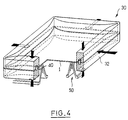
- This clamping member 30 made for example of composite material consists of an upper clamp 31 and a lower clamp 32 and has the shape of a frame as shown in FIG. 4.
- the upper clamp 31 is supported by a plate 33, by means of the screws 34 arranged inside the oblong holes 35 provided in the upper clamp 31, so as to allow lateral movement of said clamp relative to the plate 33.
- This plate 33 is supported by the intermediate sole 18 by balusters 36 slidably mounted in said sole. Compression springs 37 are interposed between the plate 33 and the midsole 18.
- the upper clamp 31 has an inclined lateral face 31a intended to cooperate with the inclined face 23c of the cams 23, in order to exert in localized areas, a lateral mechanical action on the clamping member 30.
- the lower clamp 32 comprises on the one hand guide rods 38 intended to penetrate holes 39 provided inside the upper clamp 31 and on the other hand pins 40 uniformly distributed around the periphery of the clamp 32 and intended to center the sheet blank 1.
- the pins 40 penetrate into holes 41 provided in the upper clamp 31 when the clamping member 30 is closed.
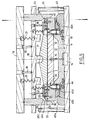
- the lower clamp 32 is supported by a frame 42 resting on counter-cams 43 which are themselves in abutment on the lower flange 10.
- the frame 42 has an external inclined face 42a.
- Each cam follower 43 has on its upper face a first inclined face 43a intended to cooperate with the inclined face 23a of the cams 23, a second inclined face 43b intended to cooperate with the inclined face 42a of the frame 42, and a third inclined face 43c intended to cooperate with complementary means 50 to orient the buckling, as will be seen later.
- Springs 44 are arranged between the bottom of the die 11 and each cam follower 43.
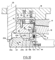
- the complementary means for orienting the buckling can be constituted by a deformable peripheral blade 50, inserted between the die 13 and the lower clamp 32 to orient the buckling of the free part 1b of the sheet blank 1 in a uniform manner and in the same direction.
- the blade 50 is constituted by an elastic blade made for example of composite material.
- a first part 50a of the blade 50 is supported on a support 51 in the form of a frame and surrounding the matrix bottom 11.
- the support 51 comprises a vertical wall plate 51a in contact with the outer wall of the die bottom 11 and a horizontal base plate 51b contiguous to an edge of the wall plate at a right angle thereto.
- the base plate 51b has its lower face 51c inclined at the same slope as the inclined face 43c of the cams 43.
- a second part 50b of the blade 50 is supported on a pusher 52 formed by a vertical plate whose lower end rests on the base plate 51b of the support 51.
- Springs 53 are disposed between the wall plate 51a and the plate 52 so as to keep said plates spaced apart and in contact respectively with the outer wall of the die bottom 11 and with the inner lateral wall of the lower clamp 32.
- the blade 50 has been shown below the sheet blank 1, which leads to a lifting of the edge, but it is obvious that one can conceive of a symmetrical version in which the edge has fallen using a blade arranged above the blank and which is used to print a downward movement.
- the sheet blank 1 is formed as follows.
- the sheet blank 1 is placed on the matrix 13 so that a small width of its peripheral edge also rests on the lower clamp 32 inside the zone delimited by the pins 40.
- the real average fiber of the sheet blank 1 is placed in a position relative to the neutral fiber of the assembly constituted by the punch 17 and the matrix 13 as can generate at least in localized areas of said sheet blank, an adjustable internal stress available to cancel any stresses induced by external phenomena such as thermal expansion and vibrations generated by acoustic, magnetic and other phenomena.
- the deformation is exerted with respect to the average fiber of the metal constituting the sheet blank to have a homogeneous deformation and so as not to deteriorate the precision of the micro-perforations in the central part of the sheet blank.
- the upper part of the blade 50 is supported below the peripheral zone 1b of the sheet blank (FIG. 6).
- controlled buckling of the free part 1b of the sheet blank is carried out between the punch 17 and the clamping member 30.
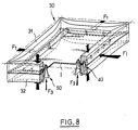
- the intermediate sole 18 being in abutment on the columns 25 and while maintaining by the clamping member 30 the peripheral part 1b of the sheet blank 1 under the action of the springs 37, it is exerted on localized zones clamps 31 and 32 of the clamping member 30, a mechanical action illustrated by the arrows F1 ( Figures 7 to 9).
- this mechanical action on each opposite branch of the clamping member 30 has the effect of inducing, by means of the small pins 40, a pushing action on the peripheral part of the sheet blank which is entirely original by compared to a conventional stamping operation carried out under the pulling action exerted by the blank under the punch.
- the bringing together of the opposite branches of the clamping member 30 causes on the part free 1b of the sheet blank 1, controlled buckling.
- This oriented buckling and occurring around the mean fiber of the sheet blank is carried out in such a way that the deformation of the peripheral zone of the sheet blank corresponds to a flow of the material, such as the thickness of the blank and the perimeter of the latter be kept substantially constant.
- This mechanical action also causes a simultaneous movement of bringing the two parts 50a and 50b of the blade 50 illustrated by the arrows F2 and rising from the top of the blade 50 illustrated by the arrow F3 ( Figures 7 and 8).
- the role of this combined movement of raising and moving the blade 50 is to orient the buckling of the free part 1b of the sheet blank 1 located between the punch-die assembly and the clamping member 30.
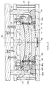
- the next phase of the process (FIGS. 10 and 11) consists in unwinding the edge 1b of the sheet blank 1 by translation in a simultaneous upward movement of the clamping member 30 and the blade 50 respectively according to arrows F4 and F5.
- the cams 23 impart via the inclined faces 23a and 43a a movement transverse to the cams 43 against the springs 44.
- the transverse movement F6 of the cams 43 in turn simultaneously prints an upward movement F4 to l clamping member 30 via the inclined face 43b of said cams and the inclined face 42a of the frame 42 and an upward movement F5 to the blade 50 via the inclined face 43c of the cams and of the inclined face 51c of the support 51.
- the slope of the inclined face 43b is greater than that of the inclined face 43c so as to obtain a vertical displacement of the clamping member 30 faster than that of the blade 50.
- the end of the free edge 1b of the sheet metal blank 1 is pressed against the side wall of the punch 17 by mounting the blade 50.
- the upper sole 19 is ascent which causes the device to open by raising the cams 23, the midsole 18, the punch 17 and the upper clamp 31.
- the jack 16 is always kept at bottom dead center to avoid the rising of the matrix 13 which would cause a deformation of the sheet blank 1 formed.
Landscapes
- Engineering & Computer Science (AREA)
- Manufacturing & Machinery (AREA)
- Mechanical Engineering (AREA)
- Shaping Metal By Deep-Drawing, Or The Like (AREA)
- Forging (AREA)
- Treatment Of Fiber Materials (AREA)
- Physical Vapour Deposition (AREA)
- Bending Of Plates, Rods, And Pipes (AREA)
Claims (19)
- Verfahren zum Verformen eines Blechzuschnitts (1), insbesondere zur Herstellung einer Maske für Kathodenstrahlröhren, auf einer Presse, wobei:- der Blechzuschnitt (1) zwischen einem Stempel (17) und einer Matrize (13) angeordnet wird,- der Randbereich des Blechzuschnitts (1) über eine geringe Breite in einer Randklemmvorrichtung (30) festgehalten wird,- der mittlere Bereich des Blechzuschnitts (1) zwischen dem Stempel (17) und der Matrize (13) geklemmt wird, dadurch gekennzeichnet, daß- der mittlere Bereich des Blechzuschnitts (1) durch Verformung des Stempels (17) und der Matrize (13) unter der Wirkung einer oberen Druckplatte (19) gemäß einer bestimmten Kontur geformt wird, dergestalt, daß die Mittelfaser des Blechzuschnitts (1) in einer bestimmten Position bezüglich der neutralen Faser des Stempel (17)-Matrizen (13)-Aufbaus angeordnet wird, derart, daß wenigstens in örtlich begrenzten Bereichen des Blechzuschnitts (1) eine einstellbare Eigenspannung erzeugt werden kann,- auf örtlich begrenzte Bereiche der Klemmvorrichtung (30) mechanisch eingewirkt wird, indem in seitlicher Richtung die gegenüberliegenden Elemente der Klemmvorrichtung einander angenähert werden, um auf dem zwischen dem Stempel (17)-Matrizen (13)-Aufbau und der Klemmvorrichtung (30) befindlichen freien Bereich (1b) des Blechzuschnitts (1), durch Bewegungseinwirkung auf den Randbereich des Blechzuschnitts (1) einen gesteuerten orientierten Knick zu erzeugen, wobei eine im wesentlichen konstante Dicke und konstante äußere Begrenzung des Blechzuschnitts aufrechterhalten wird,- gleichzeitig der Randbereich (1b) des Blechzuschnitts durch eine Relativbewegung der Klemmvorrichtung (30) bezüglich des Stempels (17) oder der Matrize (13) zur Herstellung eines Fertigsaumstreifens längs der Seitenwände des Stempels (17) oder der Matrize (13) angelegt und abgerollt wird.
- Verfahren nach Anspruch 1, dadurch gekennzeichnet, daß während des Knickens des freien Bereichs (1b) des Blechzuschnitts (1) die Verformung des freien Bereiches ausgerichtet wird.
- Vorrichtung zum Verformen eines Blechzuschnitts (1), insbesondere zur Herstellung einer Maske für eine Kathodenstrahlröhre, auf einer Presse, welche eine Matrize (13) und einen von einer oberen Druckplatte (19) mittels einer mittleren Druckplatte (18) gehalterten Stempel (17), und eine Klemmvorrichtung für den Randbereich des Bleches (1) aufweist, dadurch gekennzeichnet, daß die Matrize (13) und der Stempel (17) aus einem verformbaren Material hergestellt sind und die Vorrichtung Mittel (23) zur mechanischen Einwirkung auf die Klemmvorrichtung (30) an örtlich begrenzten Bereichen, indem in seitlicher Richtung die einander gegenüberliegenden Elemente der Klemmvorrichtung (30) einander angenähert werden, Mittel (23, 42, 43) zur vertikalen Verschiebung der Klemmvorrichtung (30) bezüglich des Stempel (17)-Matrizen (13)-Aufbaus und eine verformbare Randlamelle (50) zur Steuerung des Knickens und zum Abrollen des Randbereichs des Blechzuschnitts längs der Seitenwände des Stempels (17) oder der Matrize (13) zur Herstellung eines Fertigsaumstreifens aufweist.
- Vorrichtung nach Anspruch 3, dadurch gekennzeichnet, daß die Randklemmvorrichtung (30) für den Blechzuschnitt (1) die Form eines Rahmens aufweist.
- Vorrichtung nach den Ansprüchen 3 und 4, dadurch gekennzeichnet, daß die Randklemmvorrichtung (30) aus einer von der mittleren Druckplatte (18) gehalterten oberen Klemme (31) und einer unteren Klemme (32) gebildet ist.
- Vorrichtung nach Anspruch 5, dadurch gekennzeichnet, daß die obere Klemme (31) auf Höhe ihrer oberen randseitigen Kante eine geneigte Fläche (31a) aufweist.
- Vorrichtung nach einem der Ansprüche 3 bis 6, dadurch gekennzeichnet, daß die Mittel zur mechanischen Einwirkung auf die Klemmvorrichtung (30) an örtliche begrenzten Bereichen durch Nocken (23) gebildet werden, die durch die obere Druckplatte (19) gehaltert werden.
- Vorrichtung nach Anspruch 7, dadurch gekennzeichnet, daß die Nocken (23) eine untere geneigte Fläche (23a) und eine Ausnehmung (23b), die mit einer mit der geneigten Fläche (31c) der Klemme (31) zusammenwirkenden geneigten Fläche (23c) versehen ist, aufweisen.
- Vorrichtung nach einem der Ansprüche 3 bis 8, dadurch gekennzeichnet, daß die Mittel zur vertikalen Verschiebung der Klemmvorrichtung (30) durch Gegennocken (43), die mit den Nocken (23) zusammenwirken, und einen Rahmen (42), der zwischen den Gegennocken (43) und der Klemmvorrichtung (30) angeordnet ist, gebildet sind.
- Vorrichtung nach Anspruch 9, dadurch gekennzeichnet, daß die Gegennocken (43) in eine zur Verschiebungsrichtung der Nocken (23) senkrechten Richtung bewegbar sind.
- Vorrichtung nach den Ansprüchen 9 und 10, dadurch gekennzeichnet, daß die Gegennocken (43) auf ihrer oberen Wand eine Folge von mehreren geneigten Flächen (43a, 43b, 43c) verschiedener Orientierung und Neigung aufweisen.
- Vorrichtung nach Anspruch 9, dadurch gekennzeichnet, daß der Rahmen (42) auf Höhe seiner äußeren randseitigen Kante mit einer geneigten Fläche (42a) gleicher Neigung wie die geneigte Fläche (43b) der Gegennocken (43) ausgebildet ist.
- Vorrichtung nach einem der Ansprüche 3 bis 12, dadurch gekennzeichnet, daß die verformbare Randlamelle (50) aus einem elastischen Element besteht, bei dem ein erster Bereich (50a) an dem Stempel (17)-Matrizen (13)-Aufbau und ein zweiter Bereich (50b) and der Klemmvorrichtung (30) anliegt.
- Vorrichtung nach Anspruch 13, dadurch gekennzeichnet, daß der erste Bereich (50a) der Lamelle (50) auf einem rahmenförmigen Träger (51) aufruht.
- Vorrichtung nach Anspruch 14, dadurch gekennzeichnet, daß der Träger (51) eine vertikale Wandplatte (51a) und eine horizontale Grundplatte (51b), die an einen Rand der Wandplatte unter Ausbildung eines rechten Winkels mit dieser angrenzt, aufweist.
- Vorrichtung nach Anspruch 15, dadurch gekennzeichnet, daß die Grundplatte (51b) eine untere Fläche (51c) aufweist, die im wesentlichen die gleiche Neigung wie die geneigte Fläche (43c) der Gegennocken (43) aufweist.
- Vorrichtung nach einem der Ansprüche 13 und 16, dadurch gekennzeichnet, daß der zweite Bereich (50b) der Lamelle (50) auf einem Drücker (52) aufliegt, der durch eine vertikale Platte gebildet wird, deren unteres Ende auf der Grundplatte (51b) des Trägers (51) ruht.
- Vorrichtung nach einem der Ansprüche 13 und 17, dadurch gekennzeichnet, daß Federn (53) zwischen der Wandplatte (51a) des Trägers (51) und dem Drücker (52) angeordnet sind.
- Vorrichtung nach Anspruch 3, dadurch gekennzeichnet, daß sie Mittel (15, 16) zum Verriegeln der Matrize (30) im unteren Totpunkt aufweist.
Priority Applications (1)
| Application Number | Priority Date | Filing Date | Title |
|---|---|---|---|
| AT89402656T ATE88384T1 (de) | 1988-10-05 | 1989-09-27 | Verfahren und vorrichtung zum verformen von blech, insbesondere zum realisieren einer lochmaske fuer kathodenstrahlroehren gemaess dem verfahren. |
Applications Claiming Priority (4)
| Application Number | Priority Date | Filing Date | Title |
|---|---|---|---|
| FR8813042A FR2637207B1 (fr) | 1988-10-05 | 1988-10-05 | Procede et dispositif de formage d'un flan de tole notamment pour realiser un masque de tube cathodique et masque de tube cathodique obtenu selon ce procede |
| FR8813042 | 1988-10-05 | ||
| FR8900545A FR2641720B1 (fr) | 1989-01-18 | 1989-01-18 | Procede et dispositif de formage d'un flan de tole notamment pour realiser un masque de tube cathodique et masque de tube cathodique obtenu selon ce procede |
| FR8900545 | 1989-01-18 |
Publications (2)
| Publication Number | Publication Date |
|---|---|
| EP0367642A1 EP0367642A1 (de) | 1990-05-09 |
| EP0367642B1 true EP0367642B1 (de) | 1993-04-21 |
Family
ID=26226915
Family Applications (1)
| Application Number | Title | Priority Date | Filing Date |
|---|---|---|---|
| EP89402656A Expired - Lifetime EP0367642B1 (de) | 1988-10-05 | 1989-09-27 | Verfahren und Vorrichtung zum Verformen von Blech, insbesondere zum Realisieren einer Lochmaske für Kathodenstrahlröhren gemäss dem Verfahren |
Country Status (9)
| Country | Link |
|---|---|
| US (1) | US5005396A (de) |
| EP (1) | EP0367642B1 (de) |
| JP (1) | JPH02148641A (de) |
| KR (1) | KR900007024A (de) |
| CN (1) | CN1024506C (de) |
| CA (1) | CA2000059A1 (de) |
| DE (1) | DE68906123T2 (de) |
| ES (1) | ES2042037T3 (de) |
| FI (1) | FI102793B1 (de) |
Families Citing this family (22)
| Publication number | Priority date | Publication date | Assignee | Title |
|---|---|---|---|---|
| US5287717A (en) * | 1992-04-03 | 1994-02-22 | Custom Metalcraft, Inc. | Method for forming a tank bottom |
| US5416378A (en) * | 1993-11-03 | 1995-05-16 | Rca Thomson Licensing Corporation | Color picture tube with iron-nickel alloy shadow mask |
| DE29506877U1 (de) * | 1995-04-24 | 1995-06-22 | Trumpf Gmbh & Co, 71254 Ditzingen | Bearbeitungsmaschine insbesondere zum Umformen von Werkstücken |
| KR100373840B1 (ko) * | 1995-11-08 | 2003-05-01 | 삼성에스디아이 주식회사 | 칼라수상관용새도우마스크의그제조방법 |
| CN1095706C (zh) * | 1997-02-14 | 2002-12-11 | 好丽友金属工业株式会社 | 用于阴极射线管的框架的制造方法和设备 |
| JP2004050230A (ja) * | 2002-07-19 | 2004-02-19 | Uchiyama Mfg Corp | 金属板のプレス加工方法 |
| US7013694B1 (en) | 2004-05-14 | 2006-03-21 | Steven Don Sims | Portable, metal bending apparatus |
| US20080307849A1 (en) * | 2004-11-26 | 2008-12-18 | Agency For Science, Technology And Research | Method And Apparatus For Forming Microstructures |
| US7484397B2 (en) * | 2006-01-12 | 2009-02-03 | Vari-Form, Inc. | Punch, apparatus and method for forming opposing holes in a hollow part, and a part formed therefrom |
| WO2008058023A2 (en) * | 2006-11-02 | 2008-05-15 | Flextronics Ap, Llc | Modular power pack assembly |
| US8671729B2 (en) * | 2010-03-02 | 2014-03-18 | GM Global Technology Operations LLC | Fluid-assisted non-isothermal stamping of a sheet blank |
| CN102791398B (zh) * | 2010-03-10 | 2015-04-15 | 斯多里机械有限责任公司 | 加工工具组件、其下料工具及相关的方法 |
| CN102441601A (zh) * | 2010-10-15 | 2012-05-09 | 杨其融 | 月牙形u形厚钢板落料零件落料工艺及落料模的替代工艺及模具 |
| CN102847786B (zh) * | 2011-07-01 | 2016-06-08 | 沈阳工业大学 | 系列化多孔复杂接插金属件的冲压方法及其专用模具 |
| US9956600B2 (en) * | 2011-08-02 | 2018-05-01 | Fairmount Technologies, Llc | Universal dies of controllable curvature |
| CN103372605A (zh) * | 2012-04-17 | 2013-10-30 | 刘雨欣 | 一种多工序冲压复合模 |
| CN103372606A (zh) * | 2012-04-17 | 2013-10-30 | 刘雨欣 | 一种微型阳极钢片连续冲压弯曲模具 |
| KR101427918B1 (ko) * | 2012-10-05 | 2014-08-08 | 현대자동차 주식회사 | 핫 스탬핑 성형 장치 및 그 방법 |
| CN104492958A (zh) * | 2014-12-03 | 2015-04-08 | 柳州通为机械有限公司 | 一种轿车座椅拖把管件的夹方打扁模具 |
| CN104475584B (zh) * | 2014-12-23 | 2017-03-15 | 无锡微研股份有限公司 | 一种保证落料翻边冲孔同心度的模具 |
| CN105195626B (zh) * | 2015-11-12 | 2017-04-05 | 鞍山发蓝股份公司 | 一种包装用钢带开式锁扣的加工模具 |
| US12318831B2 (en) * | 2021-07-22 | 2025-06-03 | Ford Motor Company | Controllable and adjustable stamping draw bead with reverse bead geometry |
Family Cites Families (7)
| Publication number | Priority date | Publication date | Assignee | Title |
|---|---|---|---|---|
| US2422883A (en) * | 1942-01-24 | 1947-06-24 | Douglas Aircraft Co Inc | Method and apparatus for flanging sheet metal |
| US2400004A (en) * | 1942-06-08 | 1946-05-07 | Republic Aviat Corp | Means for forming sheet metal |
| US3344646A (en) * | 1961-03-15 | 1967-10-03 | Reynolds Metals Co | Method for making thin metal sheet tapered receptacles |
| US3296850A (en) * | 1964-08-25 | 1967-01-10 | Rauland Corp | Mask forming |
| US4615205A (en) * | 1984-06-18 | 1986-10-07 | Rca Corporation | Forming a shadow mask from a flat blank |
| EP0179506B1 (de) * | 1984-09-28 | 1989-08-02 | Koninklijke Philips Electronics N.V. | Verfahren und Vorrichtung zum Tiefziehen und Biegen einer Schattenmaske für Farbfernsehbildröhre |
| JPS61123425A (ja) * | 1984-11-20 | 1986-06-11 | Matsushita Electric Ind Co Ltd | 金型装置 |
-
1989
- 1989-09-27 EP EP89402656A patent/EP0367642B1/de not_active Expired - Lifetime
- 1989-09-27 ES ES198989402656T patent/ES2042037T3/es not_active Expired - Lifetime
- 1989-09-27 DE DE89402656T patent/DE68906123T2/de not_active Expired - Fee Related
- 1989-09-29 KR KR1019890014060A patent/KR900007024A/ko not_active Withdrawn
- 1989-10-02 CA CA002000059A patent/CA2000059A1/en not_active Abandoned
- 1989-10-04 FI FI894696A patent/FI102793B1/fi not_active IP Right Cessation
- 1989-10-04 US US07/416,918 patent/US5005396A/en not_active Expired - Lifetime
- 1989-10-05 JP JP1261256A patent/JPH02148641A/ja active Pending
- 1989-10-05 CN CN89107645A patent/CN1024506C/zh not_active Expired - Fee Related
Also Published As
| Publication number | Publication date |
|---|---|
| CN1024506C (zh) | 1994-05-18 |
| FI894696A0 (fi) | 1989-10-04 |
| ES2042037T3 (es) | 1993-12-01 |
| FI894696A7 (fi) | 1990-04-06 |
| DE68906123D1 (de) | 1993-05-27 |
| JPH02148641A (ja) | 1990-06-07 |
| DE68906123T2 (de) | 1993-12-02 |
| CA2000059A1 (en) | 1990-04-05 |
| US5005396A (en) | 1991-04-09 |
| FI102793B (fi) | 1999-02-15 |
| EP0367642A1 (de) | 1990-05-09 |
| FI102793B1 (fi) | 1999-02-15 |
| KR900007024A (ko) | 1990-05-09 |
| CN1041549A (zh) | 1990-04-25 |
Similar Documents
| Publication | Publication Date | Title |
|---|---|---|
| EP0367642B1 (de) | Verfahren und Vorrichtung zum Verformen von Blech, insbesondere zum Realisieren einer Lochmaske für Kathodenstrahlröhren gemäss dem Verfahren | |
| EP0435722B1 (de) | Verfahren und Vorrichtung zum Formen eines Blechzuschnittes insbesondere zur Herstellung einer Maske für eine Kathodenstrahlröhre | |
| EP0376808B1 (de) | Verfahren und Vorrichtung zum Tiefziehen von Blattmaterialien mit einem deformierbaren Stempel unter einem Tauchkolben | |
| CH413338A (fr) | Procédé de fabrication d'objets à partir d'une feuille de matière plastique et machine pour la mise en oeuvre de ce procédé | |
| FR2475945A1 (fr) | Procede de preparation des bords de la tole dans le procede de formage des tubes a la presse dit uo et appareil pour sa mise en oeuvre | |
| FR2767809A1 (fr) | Procede de fabrication d'un recipient en verre | |
| FR2641720A1 (fr) | Procede et dispositif de formage d'un flan de tole notamment pour realiser un masque de tube cathodique et masque de tube cathodique obtenu selon ce procede | |
| FR2501544A1 (fr) | Assemblage de matrices pour le refaconnage d'un article ayant une forme irreguliere | |
| FR2606364A1 (fr) | Machine de conditionnement effectuant simultanement la fixation d'un opercule sur un contenant et sa decoupe au format | |
| CA2031859C (fr) | Procede et dispositif d'emboutissage de recipients de forme tronconique, et recipient ainsi embouti | |
| EP0278831A1 (de) | Verfahren zum Montieren einer Schattenmaske in einer dreifarbigen Kathodenstrahlröhre und Kathodenstrahlröhre mit einer nach diesem Verfahren montierten Schattenmaske | |
| EP0844071B1 (de) | Vorrichtung zur Herstellung von Wellpappen | |
| FR2637207A1 (fr) | Procede et dispositif de formage d'un flan de tole notamment pour realiser un masque de tube cathodique et masque de tube cathodique obtenu selon ce procede | |
| EP0389323B1 (de) | Vorrichtung zum Biegen und Härten einer Glasscheibe | |
| FR2523485A1 (fr) | Procede et appareil de formage d'une tole avec reduction importante | |
| FR3092504A1 (fr) | Procédé de formage hybride et dispositif de formage correspondant | |
| EP0596050B1 (de) | Verfahren zuer statischen formung von gewalzten raendern fuer einen lampenschirm | |
| FR2681282A1 (fr) | Procede pour le cintrage dans un plan d'un profile en materiau composite constitue de fibres longues dans une matrice thermoplastique. | |
| FR2897001A3 (fr) | 02ocede et outil d'emboutissage d'un flan metallique. | |
| KR102935602B1 (ko) | 판형의 금속재를 이용한 프레스 금형 | |
| CH389233A (fr) | Procédé de formation d'un article creux en matière thermoplastique et appareil pour sa mise en oeuvre | |
| FR2733177A1 (fr) | Procede et dispositif d'emboutissage de pieces de formes non demoulables | |
| CA2259102A1 (fr) | Systeme de formage des abat-jour | |
| EP0214054B1 (de) | Kümpelverfahren zum Herstellen steifer Metallteile zur Bildung von Wärmeschutzbekleidungen von Rohren, Ummantelungen und dergleichen | |
| FR2793505A1 (fr) | Dispositif de fabrication de dalles de paroi |
Legal Events
| Date | Code | Title | Description |
|---|---|---|---|
| PUAI | Public reference made under article 153(3) epc to a published international application that has entered the european phase |
Free format text: ORIGINAL CODE: 0009012 |
|
| AK | Designated contracting states |
Kind code of ref document: A1 Designated state(s): AT BE CH DE ES FR GB GR IT LI LU NL SE |
|
| 17P | Request for examination filed |
Effective date: 19900510 |
|
| 17Q | First examination report despatched |
Effective date: 19911128 |
|
| GRAA | (expected) grant |
Free format text: ORIGINAL CODE: 0009210 |
|
| AK | Designated contracting states |
Kind code of ref document: B1 Designated state(s): AT BE CH DE ES FR GB GR IT LI LU NL SE |
|
| REF | Corresponds to: |
Ref document number: 88384 Country of ref document: AT Date of ref document: 19930515 Kind code of ref document: T |
|
| REF | Corresponds to: |
Ref document number: 68906123 Country of ref document: DE Date of ref document: 19930527 |
|
| ITF | It: translation for a ep patent filed | ||
| GBT | Gb: translation of ep patent filed (gb section 77(6)(a)/1977) |
Effective date: 19930728 |
|
| REG | Reference to a national code |
Ref country code: GR Ref legal event code: FG4A Free format text: 3008575 |
|
| REG | Reference to a national code |
Ref country code: ES Ref legal event code: FG2A Ref document number: 2042037 Country of ref document: ES Kind code of ref document: T3 |
|
| EPTA | Lu: last paid annual fee | ||
| PLBE | No opposition filed within time limit |
Free format text: ORIGINAL CODE: 0009261 |
|
| STAA | Information on the status of an ep patent application or granted ep patent |
Free format text: STATUS: NO OPPOSITION FILED WITHIN TIME LIMIT |
|
| 26N | No opposition filed | ||
| EAL | Se: european patent in force in sweden |
Ref document number: 89402656.6 |
|
| REG | Reference to a national code |
Ref country code: GB Ref legal event code: IF02 |
|
| PGFP | Annual fee paid to national office [announced via postgrant information from national office to epo] |
Ref country code: NL Payment date: 20020815 Year of fee payment: 14 Ref country code: CH Payment date: 20020815 Year of fee payment: 14 |
|
| PGFP | Annual fee paid to national office [announced via postgrant information from national office to epo] |
Ref country code: SE Payment date: 20020816 Year of fee payment: 14 |
|
| PGFP | Annual fee paid to national office [announced via postgrant information from national office to epo] |
Ref country code: AT Payment date: 20020820 Year of fee payment: 14 |
|
| PGFP | Annual fee paid to national office [announced via postgrant information from national office to epo] |
Ref country code: GR Payment date: 20020822 Year of fee payment: 14 |
|
| PGFP | Annual fee paid to national office [announced via postgrant information from national office to epo] |
Ref country code: ES Payment date: 20020904 Year of fee payment: 14 |
|
| PGFP | Annual fee paid to national office [announced via postgrant information from national office to epo] |
Ref country code: LU Payment date: 20020911 Year of fee payment: 14 Ref country code: DE Payment date: 20020911 Year of fee payment: 14 |
|
| PGFP | Annual fee paid to national office [announced via postgrant information from national office to epo] |
Ref country code: FR Payment date: 20020917 Year of fee payment: 14 |
|
| PGFP | Annual fee paid to national office [announced via postgrant information from national office to epo] |
Ref country code: GB Payment date: 20020920 Year of fee payment: 14 |
|
| PGFP | Annual fee paid to national office [announced via postgrant information from national office to epo] |
Ref country code: BE Payment date: 20021011 Year of fee payment: 14 |
|
| PG25 | Lapsed in a contracting state [announced via postgrant information from national office to epo] |
Ref country code: LU Free format text: LAPSE BECAUSE OF NON-PAYMENT OF DUE FEES Effective date: 20030927 Ref country code: GB Free format text: LAPSE BECAUSE OF NON-PAYMENT OF DUE FEES Effective date: 20030927 Ref country code: AT Free format text: LAPSE BECAUSE OF NON-PAYMENT OF DUE FEES Effective date: 20030927 |
|
| PG25 | Lapsed in a contracting state [announced via postgrant information from national office to epo] |
Ref country code: SE Free format text: LAPSE BECAUSE OF NON-PAYMENT OF DUE FEES Effective date: 20030928 |
|
| PG25 | Lapsed in a contracting state [announced via postgrant information from national office to epo] |
Ref country code: ES Free format text: LAPSE BECAUSE OF NON-PAYMENT OF DUE FEES Effective date: 20030929 |
|
| PG25 | Lapsed in a contracting state [announced via postgrant information from national office to epo] |
Ref country code: LI Free format text: LAPSE BECAUSE OF NON-PAYMENT OF DUE FEES Effective date: 20030930 Ref country code: CH Free format text: LAPSE BECAUSE OF NON-PAYMENT OF DUE FEES Effective date: 20030930 Ref country code: BE Free format text: LAPSE BECAUSE OF NON-PAYMENT OF DUE FEES Effective date: 20030930 |
|
| BERE | Be: lapsed |
Owner name: *SOLLAC Effective date: 20030930 |
|
| PG25 | Lapsed in a contracting state [announced via postgrant information from national office to epo] |
Ref country code: NL Free format text: LAPSE BECAUSE OF NON-PAYMENT OF DUE FEES Effective date: 20040401 Ref country code: DE Free format text: LAPSE BECAUSE OF NON-PAYMENT OF DUE FEES Effective date: 20040401 |
|
| PG25 | Lapsed in a contracting state [announced via postgrant information from national office to epo] |
Ref country code: GR Free format text: LAPSE BECAUSE OF NON-PAYMENT OF DUE FEES Effective date: 20040402 |
|
| EUG | Se: european patent has lapsed | ||
| REG | Reference to a national code |
Ref country code: CH Ref legal event code: PL |
|
| GBPC | Gb: european patent ceased through non-payment of renewal fee |
Effective date: 20030927 |
|
| PG25 | Lapsed in a contracting state [announced via postgrant information from national office to epo] |
Ref country code: FR Free format text: LAPSE BECAUSE OF NON-PAYMENT OF DUE FEES Effective date: 20040528 |
|
| NLV4 | Nl: lapsed or anulled due to non-payment of the annual fee |
Effective date: 20040401 |
|
| REG | Reference to a national code |
Ref country code: FR Ref legal event code: ST |
|
| REG | Reference to a national code |
Ref country code: ES Ref legal event code: FD2A Effective date: 20030929 |
|
| PG25 | Lapsed in a contracting state [announced via postgrant information from national office to epo] |
Ref country code: IT Free format text: LAPSE BECAUSE OF NON-PAYMENT OF DUE FEES;WARNING: LAPSES OF ITALIAN PATENTS WITH EFFECTIVE DATE BEFORE 2007 MAY HAVE OCCURRED AT ANY TIME BEFORE 2007. THE CORRECT EFFECTIVE DATE MAY BE DIFFERENT FROM THE ONE RECORDED. Effective date: 20050927 |