EP0367691A1 - Einheit zur technischen Kontrolle von Gebäuden mit steckbarem Parameterspeicher - Google Patents
Einheit zur technischen Kontrolle von Gebäuden mit steckbarem Parameterspeicher Download PDFInfo
- Publication number
- EP0367691A1 EP0367691A1 EP89420415A EP89420415A EP0367691A1 EP 0367691 A1 EP0367691 A1 EP 0367691A1 EP 89420415 A EP89420415 A EP 89420415A EP 89420415 A EP89420415 A EP 89420415A EP 0367691 A1 EP0367691 A1 EP 0367691A1
- Authority
- EP
- European Patent Office
- Prior art keywords
- tracks
- card
- memory
- central unit
- assembly according
- Prior art date
- Legal status (The legal status is an assumption and is not a legal conclusion. Google has not performed a legal analysis and makes no representation as to the accuracy of the status listed.)
- Withdrawn
Links
Images


Classifications
-
- H—ELECTRICITY
- H05—ELECTRIC TECHNIQUES NOT OTHERWISE PROVIDED FOR
- H05K—PRINTED CIRCUITS; CASINGS OR CONSTRUCTIONAL DETAILS OF ELECTRIC APPARATUS; MANUFACTURE OF ASSEMBLAGES OF ELECTRICAL COMPONENTS
- H05K1/00—Printed circuits
- H05K1/02—Details
- H05K1/11—Printed elements for providing electric connections to or between printed circuits
- H05K1/117—Pads along the edge of rigid circuit boards, e.g. for pluggable connectors
-
- G—PHYSICS
- G05—CONTROLLING; REGULATING
- G05B—CONTROL OR REGULATING SYSTEMS IN GENERAL; FUNCTIONAL ELEMENTS OF SUCH SYSTEMS; MONITORING OR TESTING ARRANGEMENTS FOR SUCH SYSTEMS OR ELEMENTS
- G05B19/00—Program-control systems
- G05B19/02—Program-control systems electric
- G05B19/04—Program control other than numerical control, i.e. in sequence controllers or logic controllers
- G05B19/12—Program control other than numerical control, i.e. in sequence controllers or logic controllers using record carriers
-
- H—ELECTRICITY
- H05—ELECTRIC TECHNIQUES NOT OTHERWISE PROVIDED FOR
- H05K—PRINTED CIRCUITS; CASINGS OR CONSTRUCTIONAL DETAILS OF ELECTRIC APPARATUS; MANUFACTURE OF ASSEMBLAGES OF ELECTRICAL COMPONENTS
- H05K1/00—Printed circuits
- H05K1/02—Details
- H05K1/0286—Programmable, customizable or modifiable circuits
- H05K1/0295—Programmable, customizable or modifiable circuits adapted for choosing between different types or different locations of mounted components
-
- H—ELECTRICITY
- H05—ELECTRIC TECHNIQUES NOT OTHERWISE PROVIDED FOR
- H05K—PRINTED CIRCUITS; CASINGS OR CONSTRUCTIONAL DETAILS OF ELECTRIC APPARATUS; MANUFACTURE OF ASSEMBLAGES OF ELECTRICAL COMPONENTS
- H05K2201/00—Indexing scheme relating to printed circuits covered by H05K1/00
- H05K2201/07—Electric details
- H05K2201/073—High voltage adaptations
- H05K2201/0746—Protection against transients, e.g. layout adapted for plugging of connector
-
- H—ELECTRICITY
- H05—ELECTRIC TECHNIQUES NOT OTHERWISE PROVIDED FOR
- H05K—PRINTED CIRCUITS; CASINGS OR CONSTRUCTIONAL DETAILS OF ELECTRIC APPARATUS; MANUFACTURE OF ASSEMBLAGES OF ELECTRICAL COMPONENTS
- H05K2201/00—Indexing scheme relating to printed circuits covered by H05K1/00
- H05K2201/09—Shape and layout
- H05K2201/09145—Edge details
-
- H—ELECTRICITY
- H05—ELECTRIC TECHNIQUES NOT OTHERWISE PROVIDED FOR
- H05K—PRINTED CIRCUITS; CASINGS OR CONSTRUCTIONAL DETAILS OF ELECTRIC APPARATUS; MANUFACTURE OF ASSEMBLAGES OF ELECTRICAL COMPONENTS
- H05K2201/00—Indexing scheme relating to printed circuits covered by H05K1/00
- H05K2201/09—Shape and layout
- H05K2201/09209—Shape and layout details of conductors
- H05K2201/09372—Pads and lands
- H05K2201/094—Array of pads or lands differing from one another, e.g. in size, pitch or thickness; Using different connections on the pads
-
- H—ELECTRICITY
- H05—ELECTRIC TECHNIQUES NOT OTHERWISE PROVIDED FOR
- H05K—PRINTED CIRCUITS; CASINGS OR CONSTRUCTIONAL DETAILS OF ELECTRIC APPARATUS; MANUFACTURE OF ASSEMBLAGES OF ELECTRICAL COMPONENTS
- H05K2201/00—Indexing scheme relating to printed circuits covered by H05K1/00
- H05K2201/09—Shape and layout
- H05K2201/09818—Shape or layout details not covered by a single group of H05K2201/09009 - H05K2201/09809
- H05K2201/09954—More mounting possibilities, e.g. on same place of PCB, or by using different sets of edge pads
-
- H—ELECTRICITY
- H05—ELECTRIC TECHNIQUES NOT OTHERWISE PROVIDED FOR
- H05K—PRINTED CIRCUITS; CASINGS OR CONSTRUCTIONAL DETAILS OF ELECTRIC APPARATUS; MANUFACTURE OF ASSEMBLAGES OF ELECTRICAL COMPONENTS
- H05K2201/00—Indexing scheme relating to printed circuits covered by H05K1/00
- H05K2201/10—Details of components or other objects attached to or integrated in a printed circuit board
- H05K2201/10007—Types of components
- H05K2201/10159—Memory
Definitions
- the invention relates to a building technical control assembly, comprising a central unit intended to be connected to a plurality of sensors and actuators for tracking the data supplied by the sensors and controlling the actuators, the central unit comprising a microprocessor, at least one backed-up RAM, a keyboard and a display device.
- the invention aims to simplify the initial programming of the assembly as much as possible.
- the assembly includes a removable memory, of the electrically erasable programmable read-only memory type, containing the parameters associated with a plurality of standard configurations corresponding to a plurality of predetermined standard applications of the assembly, the removable memory being arranged in a plug-in cartridge intended to be temporarily connected to the central unit for the initial programming of the assembly, when it is put into service, so as to allow the transfer from the removable memory to the memory long live parameters associated with a configuration selected by the keyboard.
- a plug-in cartridge containing in memory all the standard configurations generally used in a particular field of application therefore allows the operator to automatically program the assembly by connecting the plug-in cartridge to the central unit and selecting using from the keyboard the configuration corresponding to his needs.
- the parameters contained in the random access memory can be displayed successively on the display device, and supplemented or modified under the control of the keyboard.
- the removable memory has empty memory locations and, certain parameters introduced into the RAM being supplemented or modified via the keyboard, all of the parameters are transferable, under the control of the keyboard, from the RAM. to empty memory locations preselected from removable memory so as to constitute a backup copy of the modified configuration.
- Connecting the removable device to the central unit when the latter is powered up can, if no care is taken, lead to disturbance or damage to certain circuits, both in the central unit and in the memory circuit.
- the central unit comprises a first printed circuit board carrying at least the microprocessor of the central unit , the plug-in cartridge comprising a second printed circuit board, one of the two cards comprising a range of connection of supply tracks and data transmission tracks on which is intended to come to plug a connector, integral with the other card and electrically connected to supply and data tracks of said other card, the ends supply tracks of said connection pad being offset with respect to the ends of the data transmission tracks of said pad, so as to come into contact with the connector before the latter when the connector is plugged in, the tracks of power supply being, in the connection area, arranged on either side of the data transmission tracks.
- the removable device comprising the memory must be supplied before the data transmission tracks are connected, thus intrinsically ensuring the protection of the circuits.
- the edge of the card is indented in the part of the connection area corresponding to the data transmission tracks.
- connection pad comprises, on one face of the card, on either side of the data transmission tracks, two adjacent supply tracks of opposite polarities, the outer tracks being likewise polarity, supply tracks can be arranged on the two opposite faces of the card symmetrically with respect to the plane of the card if a double-sided printed circuit is used.
- the card is normally placed in a housing comprising a polarizing device so as to allow the plugging in of the connector in a predetermined direction only.
- connection pad comprising on a first face a supply track of polarity at a first end and a track of power supply of opposite polarity at the other end, and vice versa on the opposite side.
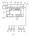
- the assembly shown in FIG. 1 essentially comprises a central unit 110 intended to be connected, if necessary by means of interfaces suitable for sensors 112 and actuators 114. In the preferred embodiment shown in the figure, this connection is made by means of a data transmission network 116 connected to the internal bus 118 of the central unit via the interface 115.
- the number and nature of the sensors and actuators depends on the type of application for which the assembly is used.
- a microprocessor 120 In the figure are diagrammed the elements of the central unit, essential for understanding the invention, namely a microprocessor 120, a read-only memory (ROM) 122, a random access memory (RAM) 124, a display device numeric 126 and a keyboard 128. In the figure all these elements are connected to the internal bus 118. It is obvious that the invention is not limited to such a structure and that any type of central unit comprising at least these elements essentials can be used.
- a removable memory of the EEPROM type, is arranged in a plug-in cartridge 130.
- the racking is done using connectors 131 and 132 located on the cartridge 130 and the central unit 110.
- the removable memory In the plugged-in position of the cartridge, the removable memory is connected to the internal bus 118. It is thus supplied by the central unit and there can be data transfer between the removable memory and the central unit.
- the removable memory of a cartridge contains the parameters associated with a certain number of standard configurations, for example around thirty standard configurations. For a given standard configuration, the number and nature of the sensors and actuators as well as their mode of use are predetermined.
- a first type of configuration could correspond to an assembly intended for controlling the heating of a building, comprising actuators 114 constituted by heating control modules and sensors 112 constituted by temperature probes.
- actuators 114 constituted by heating control modules and sensors 112 constituted by temperature probes.
- Each configuration of this type will specify the necessary parameters defining the equipment used - number of modules and number of outputs per module, type of probe - and its use - type of heating (by convection, by slab ...), timetables, etc.
- a second type of configuration could correspond to the use of a set for the simultaneous control of the heating and lighting of a building.
- Each cartridge will be associated with a descriptive list of the standard configurations it contains so as to allow the operator to select the configuration corresponding to his application.
- a "Hotel” cartridge may contain the different standard configurations necessary for the technical control of a hotel, while a "School” cartridge will contain the different standard configurations generally encountered in the technical control of a school. .
- the central unit 110 is powered up and under the control of the keyboard, a configuration subroutine contained in the read-only memory 122 initiates the dialogue with the operator via the display device 126. Possibly after a first exchange of information necessary for initialization and customization of the assembly, a question relating to the configuration chosen is then displayed. The operator can then decide not to use standard configuration and programming is then carried out in a conventional manner by successively entering all the necessary parameters. Otherwise, it connects a plug-in cartridge 130 to the central unit and selects, via the keyboard, the configuration corresponding to its application. The content of the removable memory corresponding to the selected configuration is then automatically transferred into the RAM 124 of the central unit.
- the operator can check the parameters entered in the RAM 124 on the display device using a "read" function key on the keyboard.
- the operator can, thanks to an appropriate keyboard dialog, complete or modify the parameters entered in RAM. It scrolls successively on the display device 126 the parameters used, a displayed parameter which can either be validated or modified by the operator, via the keyboard. Even if the configuration needs to be slightly completed or modified, it is obvious that the use of the cartridge considerably facilitates programming.
- the saved configuration can be used later to reprogram the assembly in the event of a failure of the central unit which has led to the erasure of all or part of the content of the RAM 124, or to program other assemblies. of the same type.
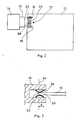
- FIG. 2 is shown schematically a printed circuit board 10, said motherboard, on which only the connection pad 12 is shown.
- a printed circuit board 10 comprises at least the microprocessor of the central unit of the assembly according to FIG. 1, and can carry the various components of the central unit.
- the removable cartridge 14, intended to be connected with the card 10, is provided with a connector 16, which can for example be a standard connector of the HE9 type.
- This connector is integral with a printed circuit board (not shown), called the daughter card, disposed inside the cartridge and carrying the memory of the cartridge.
- the connection of the connector 16 to the connection pad 12 must make the connection of the power supply tracks and the data transmission tracks, respectively, of the mother and daughter cards.
- the ends of the supply tracks 18 are offset towards the outside with respect to the ends of the data transmission tracks 20.
- the supply tracks 18 are arranged on either side of the data transmission tracks 20.
- the distance "d" must be greater than the tolerances existing in the connector as for the positioning of the axis 24 and less than the depth of the connector. In practice, a distance corresponding to 1/2 step of the printed circuit grid, or 1.27 mm, has been found to be satisfactory.
- the edge of the card 10 is indented in the part of the connection area corresponding to the data transmission tracks 18, thus physically delimiting the plane 28, the ends of the tracks going up to at the edge of the card.
- This characteristic is not essential, in particular when the tracks are tinned, which is possible when the number of racking-in maneuvers provided is limited - for example 50 maneuvers -.
- the connection pad is of the type shown diagrammatically in FIG. 9.
- the tracks are made by depositing gold so as to withstand a large number of racking-in maneuvers, the embodiment according to Figure 2 is required.
- Figures 4 to 6 illustrate various possible distributions of the supply tracks within the connection area.
- the data transmission tracks which are available opposite the wall 28 have not been shown.
- FIG. 4 illustrates the preferred embodiment of the connection pad.
- Each face has two supply tracks 18, of opposite polarities.
- these polarities are shown diagrammatically by the references + and -, but it is obvious that one of the tracks may be grounded, the other being at a positive voltage, for example + 5V, or negative, by example -5V.
- a track of polarity given on one of the faces corresponds to a track of opposite polarity on the opposite face.
- the supply tracks + and - arranged on the same side of the data transmission tracks, on the opposite faces of the card ensure contact, both other supply tracks, arranged on the other side of the data transmission tracks ensuring contact in the position shown in dotted lines in FIG. 9.
- a reversal of the connector this is to saying a plug-in so that the contacts normally associated with the upper face are in contact with the lower face of the card, also ensures correct connection of the supply tracks.
- the data transmission tracks are not connected correctly, but the correct connection of the power supply tracks avoids deterioration of the memory and it is then sufficient to turn the connector over to obtain correct operation.
- the tracks are all arranged on the same face of the card, two adjacent supply tracks of opposite polarities being arranged on either side of the data transmission tracks, the two outermost tracks being of the same polarity.
- FIG. 6 illustrates a third possible embodiment, derived from that shown in FIG. 5, supply tracks also being formed on the underside of the card, symmetrically with respect to the plane of the card. This then ensures correct connection of the supply tracks in all cases.
- the motherboard which includes the connection pad. It is also possible to have such a range on the daughter board, the connector then being secured to the mother board.
Landscapes
- Engineering & Computer Science (AREA)
- Microelectronics & Electronic Packaging (AREA)
- Physics & Mathematics (AREA)
- General Physics & Mathematics (AREA)
- Automation & Control Theory (AREA)
- Coupling Device And Connection With Printed Circuit (AREA)
Applications Claiming Priority (4)
| Application Number | Priority Date | Filing Date | Title |
|---|---|---|---|
| FR8815057 | 1988-11-04 | ||
| FR8815050A FR2638932B1 (fr) | 1988-11-04 | 1988-11-04 | Carte de circuit imprime comportant une plage de connexion a un connecteur amovible |
| FR8815050 | 1988-11-04 | ||
| FR8815057A FR2638863B1 (fr) | 1988-11-04 | 1988-11-04 | Ensemble de controle technique de batiment, a memoire embrochable de parametrage |
Publications (1)
| Publication Number | Publication Date |
|---|---|
| EP0367691A1 true EP0367691A1 (de) | 1990-05-09 |
Family
ID=26226996
Family Applications (1)
| Application Number | Title | Priority Date | Filing Date |
|---|---|---|---|
| EP89420415A Withdrawn EP0367691A1 (de) | 1988-11-04 | 1989-10-25 | Einheit zur technischen Kontrolle von Gebäuden mit steckbarem Parameterspeicher |
Country Status (1)
| Country | Link |
|---|---|
| EP (1) | EP0367691A1 (de) |
Cited By (1)
| Publication number | Priority date | Publication date | Assignee | Title |
|---|---|---|---|---|
| FR2698976A1 (fr) * | 1992-12-09 | 1994-06-10 | Delta Dore | Appareil de commande programmable d'une installation de chauffage. |
Citations (5)
| Publication number | Priority date | Publication date | Assignee | Title |
|---|---|---|---|---|
| FR2291547A1 (fr) * | 1974-11-13 | 1976-06-11 | Renault | Calculateur directeur de processus industriels |
| GB1481700A (en) * | 1974-06-06 | 1977-08-03 | Quantel Ltd | Interconnection of circuit boards |
| FR2356985A1 (fr) * | 1976-06-28 | 1978-01-27 | Fujitsu Fanuc Ltd | Unite de commande numerique pour machine-outil comportant une memoire a cassette |
| EP0102079A2 (de) * | 1982-08-30 | 1984-03-07 | rotring-werke Riepe KG | Verfahren und Anordnung zum Programmieren eines Festwert-Speichers eines digital gesteuerten Zeichengerätes |
| EP0184657A2 (de) * | 1984-10-31 | 1986-06-18 | Flexible Computer Corporation | Digitales Multirechner-Verarbeitungssystem |
-
1989
- 1989-10-25 EP EP89420415A patent/EP0367691A1/de not_active Withdrawn
Patent Citations (5)
| Publication number | Priority date | Publication date | Assignee | Title |
|---|---|---|---|---|
| GB1481700A (en) * | 1974-06-06 | 1977-08-03 | Quantel Ltd | Interconnection of circuit boards |
| FR2291547A1 (fr) * | 1974-11-13 | 1976-06-11 | Renault | Calculateur directeur de processus industriels |
| FR2356985A1 (fr) * | 1976-06-28 | 1978-01-27 | Fujitsu Fanuc Ltd | Unite de commande numerique pour machine-outil comportant une memoire a cassette |
| EP0102079A2 (de) * | 1982-08-30 | 1984-03-07 | rotring-werke Riepe KG | Verfahren und Anordnung zum Programmieren eines Festwert-Speichers eines digital gesteuerten Zeichengerätes |
| EP0184657A2 (de) * | 1984-10-31 | 1986-06-18 | Flexible Computer Corporation | Digitales Multirechner-Verarbeitungssystem |
Non-Patent Citations (1)
| Title |
|---|
| IBM TECHNICAL DISCLOSURE BULLETIN. vol. 21, no. 4, septembre 1978, NEW YORK US page 1407 ARVANITAKIS N.C. et al.: "Symmetrical Design for Polarized Capacitor" * |
Cited By (1)
| Publication number | Priority date | Publication date | Assignee | Title |
|---|---|---|---|---|
| FR2698976A1 (fr) * | 1992-12-09 | 1994-06-10 | Delta Dore | Appareil de commande programmable d'une installation de chauffage. |
Similar Documents
| Publication | Publication Date | Title |
|---|---|---|
| FR2601791A1 (fr) | Cartouche de memoire | |
| EP0461971B1 (de) | Elektronische Verbindungsvorrichtung | |
| EP0621600A1 (de) | Physische Anordnung einer Untergruppe von Speichereinheit | |
| FR2461299A1 (fr) | Memoire bloc-note pour cassettes d'enregistrement de bandes magnetiques | |
| FR2590414A1 (fr) | Procede et dispositif d'identification electrique de cartes de circuit | |
| WO1996024111A1 (fr) | Connecteur pour appareil lecteur de carte a microcircuit et lecteur de carte comprenant un tel connecteur | |
| FR2576131A1 (fr) | Dispositif d'enregistrement/lecture a memoire electronique modulaire | |
| FR2570524A1 (fr) | Terminal de tele-informatique a extensions externes | |
| EP0124412B1 (de) | Anlage für die Herstellung von elektrischen Verdrahtungsstücken | |
| FR2637710A1 (fr) | Procede et dispositif de commande electronique multifonction a haute securite comportant une carte a puce | |
| EP0285955B1 (de) | Koppelvorrichtung für nichtflüchtige Speicher in einer elektronischen Maschine und ihre Anwendung in Frankiermaschinen | |
| EP1271450A1 (de) | Flugsimulator dass zur Flugzeugfamilie angepasst ist | |
| FR2762473A1 (fr) | Enveloppe pour appareillages electriques | |
| EP1659492B1 (de) | Autonome elektronische Vorrichtung, insbesondere ein ambulantes medizinisches Aufnahmegerät, mit einem reprogrammierbaren Mikrocontroller | |
| FR2692694A1 (fr) | Système informatique adaptable au type de microprocesseur installé et procédé de détection du type de microprocesseur. | |
| EP0714076A1 (de) | Tragbarer Gegenstand mit einer elektronischen Schaltung, betrieben durch eine innere Batterie und mit einem Datenspeicher, Verfahren und Vorrichtung zur äusserlichen Speisung dieses Gegenstandes und Datenübertragung mit letzterem | |
| FR2638932A1 (fr) | Carte de circuit imprime comportant une plage de connexion a un connecteur amovible | |
| FR2763718A1 (fr) | Connecteur avec insertion directe ou indirecte d'une carte a puce en son sein | |
| EP3475864B1 (de) | Gehäuse für die verwaltung von informationen zu einem industriestandort | |
| KR100999319B1 (ko) | 전자기기 연결용 커넥터 | |
| FR2638863A1 (fr) | Ensemble de controle technique de batiment, a memoire embrochable de parametrage | |
| FR3077685A1 (fr) | Connecteur, architecture electrique et aeronef | |
| FR2608804A1 (fr) | Module d'extension pour terminal de teleinformatique | |
| FR2696048A1 (fr) | Dispositif de connexion pour installation de transmission de signaux. | |
| WO2013010899A1 (fr) | Cartouche de communication amovible d'un équipement, équipement, ensemble et système correspondants |
Legal Events
| Date | Code | Title | Description |
|---|---|---|---|
| PUAI | Public reference made under article 153(3) epc to a published international application that has entered the european phase |
Free format text: ORIGINAL CODE: 0009012 |
|
| AK | Designated contracting states |
Kind code of ref document: A1 Designated state(s): BE CH DE ES GB IT LI SE |
|
| 17P | Request for examination filed |
Effective date: 19901015 |
|
| 17Q | First examination report despatched |
Effective date: 19930727 |
|
| STAA | Information on the status of an ep patent application or granted ep patent |
Free format text: STATUS: THE APPLICATION IS DEEMED TO BE WITHDRAWN |
|
| 18D | Application deemed to be withdrawn |
Effective date: 19940222 |