EP0367727A2 - Equipment for overturning stacks of sheet material - Google Patents
Equipment for overturning stacks of sheet material Download PDFInfo
- Publication number
- EP0367727A2 EP0367727A2 EP89830391A EP89830391A EP0367727A2 EP 0367727 A2 EP0367727 A2 EP 0367727A2 EP 89830391 A EP89830391 A EP 89830391A EP 89830391 A EP89830391 A EP 89830391A EP 0367727 A2 EP0367727 A2 EP 0367727A2
- Authority
- EP
- European Patent Office
- Prior art keywords
- frame
- axis
- equipment
- rotation
- locating surface
- Prior art date
- Legal status (The legal status is an assumption and is not a legal conclusion. Google has not performed a legal analysis and makes no representation as to the accuracy of the status listed.)
- Withdrawn
Links
- 239000000463 material Substances 0.000 title claims description 4
- 239000011111 cardboard Substances 0.000 description 5
- 239000000123 paper Substances 0.000 description 3
- 239000011087 paperboard Substances 0.000 description 2
- 239000000853 adhesive Substances 0.000 description 1
- 230000001070 adhesive effect Effects 0.000 description 1
- 238000010276 construction Methods 0.000 description 1
- 239000012530 fluid Substances 0.000 description 1
- 230000005484 gravity Effects 0.000 description 1
- 238000004519 manufacturing process Methods 0.000 description 1
Images

Classifications
-
- B—PERFORMING OPERATIONS; TRANSPORTING
- B65—CONVEYING; PACKING; STORING; HANDLING THIN OR FILAMENTARY MATERIAL
- B65H—HANDLING THIN OR FILAMENTARY MATERIAL, e.g. SHEETS, WEBS, CABLES
- B65H15/00—Overturning articles
- B65H15/02—Overturning piles
Definitions
- equipment comprises a first frame 1 serving to support the stack 2 of sheets (paper, cardboard), and a second frame 6 supporting the first frame.
- the first frame 1 comprises at least one surface 3 against which one upright face of the stack 2 is made to locate initially, and two sets of prongs 4 and 5 disposed parallel one with the other and at right angles to the locating surface 3.
- the frame 1 can be rotated manually about the second axis 'y', now vertically disposed, in such a way as to turn the stack 2 through 180° (arrow F1, fig 4). This done, the cylinder 7 is retracted so as to return the frame 1 to the lowered limit position of fig 1 in readiness for release of the stack 2, now completely upturned through the prescribed 180°.
Landscapes
- Engineering & Computer Science (AREA)
- Mechanical Engineering (AREA)
- Pile Receivers (AREA)
- Registering Or Overturning Sheets (AREA)
- Sheets, Magazines, And Separation Thereof (AREA)
Abstract
The stack of sheets (2) to be overturned is carried in a first frame (1) of the equipment, positioned with one edge butted against a locating surface (3) and held between two sets of prongs (4, 5) that enter into contact with the bottom and top sheets; this first frame is hinged to a supporting second frame (6) about a horizontal first axis (x) lying parallel with the locating surface, and can also be swivelled relative to the second frame (6) about a second axis (y) normal to the locating surface (3).
Description
- The invention relates to equipment for overturning stacks of single sheets (paper, cardboard etc.). Conventionally, large size sheets of material such as those used for billboard displays are subjected to manufacturing operations on both sides, for example the application of print to one side, and of an adhesive to the other. These operations are effected in two distinct steps; in a first step, a given operation is carried out on one side only of all the sheets of the stack, whereupon the stack is overturned, and the second operation carried out on the remaining side of each sheet.
- The question that arises, clearly enough, is that of how the stacked sheets may be overturned swiftly on completion of the first step, and preferably, in a single manoeuvre.
- The prior art embraces fixed and/or mobile types of equipment by means of which to overturn stacks of paper and/or cardboard sheets, including sheets of significantly large dimensions.
- One such item of equipment, for example, consists in a structure designed to carry and encompass the stack of sheets, the reverse side of which (i.e. the side opposite that accommodating the sheets) affords a pair of semicircular rails slidably mounted to relative guides provided with bearing rollers on which the structure, loaded up with sheets, can be rotated about a horizontal axis passing through the centre of a circle coinciding with the semicircular rails in such a way as to turn the sheets around into a position removed 180° from the point of departure.
- Another design of equipment for overturning stacks of sheets consists in a structure provided with a platform, serving to support the stack of paper or cardboard sheets, which is provided on one side with a vertically disposed and rigidly associated frame; the structure further comprises a shelf disposed at right angles to the platform, which is capable of sliding longitudinally along the frame and rotatable about its own perpendicular axis, hence about an axis parallel with the platform. The stack of sheets is positioned on the platform with one upright face butted against the shelf, whereupon the operator tilts the entire structure through 90° about a centre coinciding with the join between the platform and the vertical frame, in such a way as to dispose the frame horizontally and the platform vertically. With the structure in this position, the stack of sheets does no more than rest against the upright platform, its weight being taken by the shelf that hitherto served as vertical guide. The shelf is now traversed along the frame by the operator, and swivelled at the same time about its perpendicular axis so as to rotate the stack of sheets through 180°; this accomplished, the structure is tilted back into its original position with the sheets lying on the platform, placed exactly as before but turned upside down. Equipment of the general designs thus outlined is complicated and cumbersome, in particular the first type mentioned, and impractical in use, especially in the case of the second type mentioned.
- Accordingly, the object of the present invention is to embody equipment for overturning stacked sheets of paper, cardboard etc., that ensures simplicity in construction and practical, swift operation. The stated object is realized with equipment as characterized in the appended claims, which affords the advantage that stacked sheets of material, even stacks of considerable weight, can be overturned without any need to rotate the entire structure of the equipment, and without any requirement for manual lifting effort on the part of the operator. The invention will now be described in detail, by way of example, with the aid of the accompanying drawings, in which:
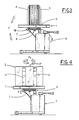
- -figs 1 and 2 illustrate equipment according to the invention, viewed in side elevation and in plan, respectively, retaining and supporting a stack of sheets to be overturned;
- -figs 3 and 4 are side elevations of equipment as in figs 1 and 2, which illustrate two successive configurations assumed as the stack of sheets is turned through 180°.
- With reference to the drawings, equipment according to the present invention comprises a
first frame 1 serving to support thestack 2 of sheets (paper, cardboard), and asecond frame 6 supporting the first frame. Thefirst frame 1 comprises at least onesurface 3 against which one upright face of thestack 2 is made to locate initially, and two sets ofprongs surface 3. - The
prongs stack 2 to be overturned. Thefirst frame 1 is hinged to thesecond frame 6, articulating about a first axis of rotation 'x' disposed horizontal and parallel to the locating surface 3 (see fig 2), and capable of movement at least between a first limit position coinciding with pick-up and release of thestack 2, in which the locatingsurface 3 is upright and theprongs surface 3 is turned horizontal, rotated through 90° from the first limit position, and theprongs - The mounting arrangement between the
first frame 1 and thesecond frame 6 also permits rotation of thefirst frame 1 in either direction, left or right, about a second axis 'y' disposed at right angles to the locating surface. - 7 and 8 denote means located between the first and
second frames first frame 1 about the first axis 'x' and to ensure its controlled support when rotating about the second axis 'y'. - Support means 8 consist in an intermediate frame 9, hinged to the
second frame 6 about the horizontal first axis 'x', to which thefirst frame 1 is mounted in such a way as enables its rotation in either direction about the second axis 'y'. - The
means 7 of producing rotation, located between thesecond frame 6 and the intermediate frame 9, consist in at least one extendible component, e.g. a double acting fluid power cylinder; such means 7 serve to rotate the first frame 1 (arrow F, fig 3) in relation to thesecond frame 6 about the first axis 'x', taking it into the second limit position in which the locatingsurface 3 is raised level. Having positioned thefirst frame 1 horizontally, and released mutual positioning means 10 associated with the intermediate and first frames 9 and 1 (consisting for example in a spring loaded detent the movement of which is arrowed 'f' in fig 4), theframe 1 can be rotated manually about the second axis 'y', now vertically disposed, in such a way as to turn thestack 2 through 180° (arrow F1, fig 4). This done, thecylinder 7 is retracted so as to return theframe 1 to the lowered limit position of fig 1 in readiness for release of thestack 2, now completely upturned through the prescribed 180°. - In a preferred embodiment of the equipment, the
prongs first frame 1 in the raised limit position, the swivel axis 'y' coincides with the centre of gravity of thestack 2; accordingly, to produce the necessary rotation, it will suffice simply to overcome such frictional forces as exist between the first andintermediate frames 1 and 9. Moreover, thestack 2 to be turned can be picked up and set down at the same height, every time. As regards thesecond frame 6, this can be embodied as a truck or trolley, so thatstacks 2 of sheets may be picked up from one machine, overturned, and transferred to a successive machine.
Claims (4)
1) Equipment for overturning stacks of sheet material, of the type consisting in:
-a first frame (1) serving to support the stack (2) of sheets to be turned, comprising at least one surface (3) against which one edge of the stacked sheets is made to locate, and two sets of prongs (4, 5) disposed parallel with one another and at right angles to the locating surface (3), which are capable of drawing together and spreading apart in mutually parallel motion;
-a second frame (6) supporting the first frame, characterized
-in that the first frame (1) is mounted pivotably to the second frame (6), articulating about a first axis of rotation (x) lying horizontal and parallel with the locating surface (3), and capable of movement at least between a first limit position coinciding with pick-up and release of the stack (2), in which the locating surface (3) is disposed vertically and the prongs (4, 5) are disposed horizontally, and a second limit position in which the locating surface (3) is disposed horizontally, rotated 90° from the first limit position, and the prongs (4, 5) are disposed vertically;
-in that the first frame (1) is carried by the second frame (6) in such a way as permits rotation in either direction about a second axis (y) lying at right angles to the locating surface (3); and
-in that it comprises means (7, 8) located between the first and second frames (1, 6), by which the first frame (1) is caused to rotate about the first axis (x), and afforded controlled support when rotating about the second axis (y), respectively.
-a first frame (1) serving to support the stack (2) of sheets to be turned, comprising at least one surface (3) against which one edge of the stacked sheets is made to locate, and two sets of prongs (4, 5) disposed parallel with one another and at right angles to the locating surface (3), which are capable of drawing together and spreading apart in mutually parallel motion;
-a second frame (6) supporting the first frame, characterized
-in that the first frame (1) is mounted pivotably to the second frame (6), articulating about a first axis of rotation (x) lying horizontal and parallel with the locating surface (3), and capable of movement at least between a first limit position coinciding with pick-up and release of the stack (2), in which the locating surface (3) is disposed vertically and the prongs (4, 5) are disposed horizontally, and a second limit position in which the locating surface (3) is disposed horizontally, rotated 90° from the first limit position, and the prongs (4, 5) are disposed vertically;
-in that the first frame (1) is carried by the second frame (6) in such a way as permits rotation in either direction about a second axis (y) lying at right angles to the locating surface (3); and
-in that it comprises means (7, 8) located between the first and second frames (1, 6), by which the first frame (1) is caused to rotate about the first axis (x), and afforded controlled support when rotating about the second axis (y), respectively.
2) Equipment as in claim 1, comprising:
-means (8) of affording controlled support embodied as an intermediate frame (9), articulating with the second frame (6) about the first axis (x), by which the first frame (1) is carried in such a way as to permit its rotation in either direction about the second axis (y);
-means (7) of producing rotation, located between and interconnecting the second frame (6) and the intermediate frame (9);
-means (10) interacting between the intermediate frame (9) and the first frame (1), by which the first frame can be detained in at least two angular positions about the second axis of rotation (y).
-means (8) of affording controlled support embodied as an intermediate frame (9), articulating with the second frame (6) about the first axis (x), by which the first frame (1) is carried in such a way as to permit its rotation in either direction about the second axis (y);
-means (7) of producing rotation, located between and interconnecting the second frame (6) and the intermediate frame (9);
-means (10) interacting between the intermediate frame (9) and the first frame (1), by which the first frame can be detained in at least two angular positions about the second axis of rotation (y).
3) Equipment as in claim 1, wherein the sets of prongs (4, 5) are disposed symmetrically on either side of the second axis of rotation (y), and their relative movement controlled in such a way that symmetry is maintained.
4) Equipment as in claim 1, wherein the second frame (6) is of mobile truck- or trolley-type embodiment.
Applications Claiming Priority (2)
| Application Number | Priority Date | Filing Date | Title |
|---|---|---|---|
| IT8803646A IT1224966B (en) | 1988-10-31 | 1988-10-31 | EQUIPMENT FOR TILTING LEAF STACKS |
| IT364688 | 1988-10-31 |
Publications (2)
| Publication Number | Publication Date |
|---|---|
| EP0367727A2 true EP0367727A2 (en) | 1990-05-09 |
| EP0367727A3 EP0367727A3 (en) | 1991-01-09 |
Family
ID=11111077
Family Applications (1)
| Application Number | Title | Priority Date | Filing Date |
|---|---|---|---|
| EP19890830391 Withdrawn EP0367727A3 (en) | 1988-10-31 | 1989-09-15 | Equipment for overturning stacks of sheet material |
Country Status (2)
| Country | Link |
|---|---|
| EP (1) | EP0367727A3 (en) |
| IT (1) | IT1224966B (en) |
Cited By (2)
| Publication number | Priority date | Publication date | Assignee | Title |
|---|---|---|---|---|
| WO1998013263A1 (en) * | 1996-09-27 | 1998-04-02 | Jomet Oy | Method and apparatus for packaging flat articles |
| DE10017451A1 (en) * | 2000-04-07 | 2001-10-18 | Busch Gerhard Gmbh | Machine for turning over stack of sheets of paper has plates between which stack fits and which are mounted on vertical frame which can be tipped over by hydraulic cylinders |
Family Cites Families (1)
| Publication number | Priority date | Publication date | Assignee | Title |
|---|---|---|---|---|
| JPS57141337A (en) * | 1981-02-24 | 1982-09-01 | Bunshiyoudou:Kk | Turnover device for stacked paper |
-
1988
- 1988-10-31 IT IT8803646A patent/IT1224966B/en active
-
1989
- 1989-09-15 EP EP19890830391 patent/EP0367727A3/en not_active Withdrawn
Cited By (4)
| Publication number | Priority date | Publication date | Assignee | Title |
|---|---|---|---|---|
| WO1998013263A1 (en) * | 1996-09-27 | 1998-04-02 | Jomet Oy | Method and apparatus for packaging flat articles |
| US6128887A (en) * | 1996-09-27 | 2000-10-10 | Jomet Oy | Method for packaging flat articles |
| CN1081573C (en) * | 1996-09-27 | 2002-03-27 | 乔梅特有限公司 | Method and apparatus for packaging flat articles |
| DE10017451A1 (en) * | 2000-04-07 | 2001-10-18 | Busch Gerhard Gmbh | Machine for turning over stack of sheets of paper has plates between which stack fits and which are mounted on vertical frame which can be tipped over by hydraulic cylinders |
Also Published As
| Publication number | Publication date |
|---|---|
| IT8803646A0 (en) | 1988-10-31 |
| EP0367727A3 (en) | 1991-01-09 |
| IT1224966B (en) | 1990-10-29 |
Similar Documents
| Publication | Publication Date | Title |
|---|---|---|
| US5871219A (en) | Table dolly | |
| CA2116075C (en) | Restraint system for a sheet shipping rack | |
| US3765550A (en) | Dolly for lifting and transporting and installing large sheets of flat glass and other flat sheet products | |
| US4509893A (en) | Device for storing and retrieving articles in a shelf stack | |
| US5037265A (en) | Method and means for lifting lateral file cabinets | |
| KR20230054923A (en) | Unloading apparatus for transporting battery rolls and method thereof | |
| US5562401A (en) | Forms tilt cart with cam action lock | |
| JPH05139527A (en) | Device for toppling sideway workpiece on pallet | |
| CN110843888A (en) | Lifting trolley | |
| CA2539840A1 (en) | Film cassette, rack and relief trolley for the film cassette, and method of handling the film cassette | |
| JP2506413Y2 (en) | Tire hanger device | |
| JPH0630351Y2 (en) | Parts assembly device | |
| CN215960949U (en) | Auxiliary fixing structure of special funeral and interment transport vehicle | |
| JP3938417B2 (en) | Transport device | |
| CN213168209U (en) | Freight transportation flatbed convenient to unloading | |
| JP3004148B2 (en) | Glass plate overturning device | |
| JPH0215445B2 (en) | ||
| JP2542099Y2 (en) | Roll-shaped base paper discharger | |
| CN210620147U (en) | Transfer equipment for processing forklift counterweight | |
| FI81068B (en) | ANORDNING FOER HANTERING AV PLAOTAR ELLER LIKNANDE. | |
| KR0132774Y1 (en) | Assembly loading system | |
| JPS6143684Y2 (en) | ||
| JP3072425B1 (en) | Roll paper empty core transfer device | |
| JP2561185Y2 (en) | Gas filling equipment | |
| JPS63212601A (en) | Winding delivery device |
Legal Events
| Date | Code | Title | Description |
|---|---|---|---|
| PUAI | Public reference made under article 153(3) epc to a published international application that has entered the european phase |
Free format text: ORIGINAL CODE: 0009012 |
|
| AK | Designated contracting states |
Kind code of ref document: A2 Designated state(s): CH DE ES FR GB LI |
|
| PUAL | Search report despatched |
Free format text: ORIGINAL CODE: 0009013 |
|
| AK | Designated contracting states |
Kind code of ref document: A3 Designated state(s): CH DE ES FR GB LI |
|
| STAA | Information on the status of an ep patent application or granted ep patent |
Free format text: STATUS: THE APPLICATION HAS BEEN WITHDRAWN |
|
| 18W | Application withdrawn |
Withdrawal date: 19910730 |