EP0367759B1 - Soupape de regulation proportionnelle - Google Patents
Soupape de regulation proportionnelle Download PDFInfo
- Publication number
- EP0367759B1 EP0367759B1 EP87905540A EP87905540A EP0367759B1 EP 0367759 B1 EP0367759 B1 EP 0367759B1 EP 87905540 A EP87905540 A EP 87905540A EP 87905540 A EP87905540 A EP 87905540A EP 0367759 B1 EP0367759 B1 EP 0367759B1
- Authority
- EP
- European Patent Office
- Prior art keywords
- pressure level
- pressure
- valve
- proportioning
- control port
- Prior art date
- Legal status (The legal status is an assumption and is not a legal conclusion. Google has not performed a legal analysis and makes no representation as to the accuracy of the status listed.)
- Expired - Lifetime
Links
- 239000012530 fluid Substances 0.000 claims abstract description 30
- 230000007246 mechanism Effects 0.000 claims description 9
- 230000008859 change Effects 0.000 claims description 4
- 230000004044 response Effects 0.000 claims description 2
- 230000009471 action Effects 0.000 description 3
- 238000007789 sealing Methods 0.000 description 2
- 238000013022 venting Methods 0.000 description 2
- 235000008733 Citrus aurantifolia Nutrition 0.000 description 1
- 235000011941 Tilia x europaea Nutrition 0.000 description 1
- 230000000694 effects Effects 0.000 description 1
- 239000004571 lime Substances 0.000 description 1
- 230000007257 malfunction Effects 0.000 description 1
Images
Classifications
-
- B—PERFORMING OPERATIONS; TRANSPORTING
- B60—VEHICLES IN GENERAL
- B60T—VEHICLE BRAKE CONTROL SYSTEMS OR PARTS THEREOF; BRAKE CONTROL SYSTEMS OR PARTS THEREOF, IN GENERAL; ARRANGEMENT OF BRAKING ELEMENTS ON VEHICLES IN GENERAL; PORTABLE DEVICES FOR PREVENTING UNWANTED MOVEMENT OF VEHICLES; VEHICLE MODIFICATIONS TO FACILITATE COOLING OF BRAKES
- B60T8/00—Arrangements for adjusting wheel-braking force to meet varying vehicular or ground-surface conditions, e.g. limiting or varying distribution of braking force
- B60T8/26—Arrangements for adjusting wheel-braking force to meet varying vehicular or ground-surface conditions, e.g. limiting or varying distribution of braking force characterised by producing differential braking between front and rear wheels
-
- B—PERFORMING OPERATIONS; TRANSPORTING
- B60—VEHICLES IN GENERAL
- B60T—VEHICLE BRAKE CONTROL SYSTEMS OR PARTS THEREOF; BRAKE CONTROL SYSTEMS OR PARTS THEREOF, IN GENERAL; ARRANGEMENT OF BRAKING ELEMENTS ON VEHICLES IN GENERAL; PORTABLE DEVICES FOR PREVENTING UNWANTED MOVEMENT OF VEHICLES; VEHICLE MODIFICATIONS TO FACILITATE COOLING OF BRAKES
- B60T15/00—Construction arrangement, or operation of valves incorporated in power brake systems and not covered by groups B60T11/00 or B60T13/00
- B60T15/02—Application and release valves
- B60T15/18—Triple or other relay valves which allow step-wise application or release and which are actuated by brake-pipe pressure variation to connect brake cylinders or equivalent to compressed air or vacuum source or atmosphere
- B60T15/20—Triple or other relay valves which allow step-wise application or release and which are actuated by brake-pipe pressure variation to connect brake cylinders or equivalent to compressed air or vacuum source or atmosphere controlled by two fluid pressures
-
- B—PERFORMING OPERATIONS; TRANSPORTING
- B60—VEHICLES IN GENERAL
- B60T—VEHICLE BRAKE CONTROL SYSTEMS OR PARTS THEREOF; BRAKE CONTROL SYSTEMS OR PARTS THEREOF, IN GENERAL; ARRANGEMENT OF BRAKING ELEMENTS ON VEHICLES IN GENERAL; PORTABLE DEVICES FOR PREVENTING UNWANTED MOVEMENT OF VEHICLES; VEHICLE MODIFICATIONS TO FACILITATE COOLING OF BRAKES
- B60T8/00—Arrangements for adjusting wheel-braking force to meet varying vehicular or ground-surface conditions, e.g. limiting or varying distribution of braking force
- B60T8/26—Arrangements for adjusting wheel-braking force to meet varying vehicular or ground-surface conditions, e.g. limiting or varying distribution of braking force characterised by producing differential braking between front and rear wheels
- B60T8/262—Arrangements for adjusting wheel-braking force to meet varying vehicular or ground-surface conditions, e.g. limiting or varying distribution of braking force characterised by producing differential braking between front and rear wheels using valves with stepped characteristics
- B60T8/263—Arrangements for adjusting wheel-braking force to meet varying vehicular or ground-surface conditions, e.g. limiting or varying distribution of braking force characterised by producing differential braking between front and rear wheels using valves with stepped characteristics for pneumatic brake systems
Definitions
- This invention relates to a proportioning control valve for a fluid pressure braking system for a tractor-trailer combination vehicle.
- Heavy duty articulated vehicles comprising a tractor pulling a loaded trailer
- the tractor normally pulls a loaded trailer
- the tractor is used in the so-called "bobtail" mode, that is, without a trailer.
- the rear brakes of the tractor must be sized to stop a loaded vehicle.
- the rear wheels of the tractor are overbraked, which may result in dangerous skidding and loss of control.
- a proportioning valve be provided to reduce the braking effort of the rear wheel brakes of the tractor.
- This proportioning valve is responsive to the pressure level in the trailer supply line which connects the braking system of the tractor to the braking system of the trailer.
- the supply line is pressurized, but when the tractor is operated in the bobtail mode the supply line is vented to atmosphere. It is also known to change the function of such valves in response to reservoir pressure.
- Such a device is known from US-A-4 455 051, which discloses a proportioning control valve for a fluid pressure braking system for a tractor-trailer combination vehicle, said system including a reservoir and a trailer supply line communicating fluid pressure from the tractor to the trailer, said control valve including a housing having an inlet port, an outlet port, and a control port, valve means in said housing responsive to the pressure level at said control port for controlling communication between said inlet port and said outlet port, and proportioning means for controlling communication between said control port and said valve means, said proportioning means being responsive to the pressure level in said supply line for shifting from a first condition permitting said valve means to establish a pressure level at said outlet port that is a first predetermined function of the pressure level at the control port to a second condition permitting said valve means to establish a pressure level at said outlet port that is a second predetermined function of the pressure level at said control port.
- the present invention is characterized in that said proportioning means in said second condition is responsive to the pressure level at the control port and the pressure level in said reservoir to change the pressure level at said outlet port at a rate which varies as a function of the pressure level in said reservoir.
- the present invention provides a proportioned brake application when the tractor is operated in the bobtail mode, but also permits equalization of the input and output pressures.
- the present invention eliminates several additional valves and fittings which were required in prior art system. Accordingly, the present invention proportions communication up to a predetermined pressure which is determine by the ratio between the control pressure and the rear reservoir pressure, and thereafter permits full unproportioned braking pressure to be made available to the tractor rear wheel brakes.
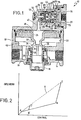
- a proportioning control valve 10 includes a housing 12 having an inlet port 14, an outlet port 16, an exhaust port 18, and a control port 20.
- the inlet port 14 is connected to the rear service reservoir on the tractor, the outlet port 16 is communicated to the rear wheel service brakes of the tractor, and the exhaust port 18 is, of course, communicated to atmosphere.
- the control port 20 is communicated to the operator actuated brake control valve is the vehicle operator's compartment. When a brake application is to be effected, the driver operated the brake control valve, to transmit a pressure signal to the control port 20 of a magnitude controlled by the vehicle operator.
- the valve 10 responds to this pressure signal to communicate the inlet port 14 with the outlet port 16 as will be hereinafter described.
- Housing 12 defines a bore 22 therewithin which slidably receives a relay piston 24.
- a combination inlet and exhaust valve mechanism valve member 26 is slidably mounted in the bore defining the exhaust port 18.
- the housing 12 defines a circumferentially extending valve seat 28, which circumscribes the bore defining the exhaust port 18.
- a spring 30 yieldably urges the combination inlet and exhaust valve 26 into sealing engagement with the valve seat 28.
- Figure 1 which illustrates the positions the relay piston 24 and inlet exhaust valve 26 assume when the brakes of the vehicle are released, the outlet poet 16, which is communicated to the rearwheel service brakes of the vehicle, is normally communicated to the exhaust port 18 through the passage defined within the inlet and exhaust valve 26.
- a stem 32 projects from the relay piston 24 and terminates a circumferentially extending valve seating area 34 which is adapted to engage the portion 36 of the inlet and exhaust valve 26.
- the region 38 above the relay piston 24 is communicated to the control port 20 through passage 40, as will be hereinafter described. Accordingly, when a brake application is effected, the fluid pressure representing the modulated brake application desired by the operator is communicated to the region 38. Since the region 38 is communicated to the higher pressure, and the region below the relay piston 24 indicated by the numeral 42 is communicated to the exhaust port 18, the piston 24 will be urged downwardly until the valve seat 34 seats against the seating area 36. This is the so-called "lap" position, in which communication between the outlet port 16 and the exhaust port 18 is cut off, but communication has not yet been initiated between the inlet port 14 and the region 42.
- the present invention relates to the proportioning mechanism generally indicated by the numeral 44 which is installed in the passage 40 and permits normal operation of the relay portion of the valve as describdd hereinabove when the tractor is connected to a trailer, but which normally proportions communication from the control port 20 into the region 38 when the tractor is operated in the "bobtail" mode. Proportioned communication establishes a proportionally lower fluid pressure level in segion 38 than that at port 20, thereby effecting a proportionally reduced brake application, which, as described hereinabove, is necessary to prevent the severe overbraking which could occur when the tractor is operated is the bobtail mode.
- the proportioning mechanism 44 includes a portion 46 of the passage 40 which slidably receives a differential area proportioning piston 48.
- exhaust passage 50 communicates the portion 46 with am exhaust port generably indicated by the numeral 52.
- the passage 50 is defined within a stem 54 which projects into a passage 56 which is defined within the piston 48.
- the passage 56 is communicated to the control port 20 and also to the region 38.
- a valve member 58 is slidably mounted in the passage 96 and is slidably urged to sealing engagement with the end of the stem 54 by a small spring 60.
- a radially inwardly projecting value seat 62 is carried by the piston 48 and is adapted to sealingly engage the valve member 58 when the piston 48 is urged to the right viewing the figure.
- valve seat 62 is moved away from the valve member 58 due to the engagement of the valve member 58 with the end of the stem 54.
- the valve member 58 is conventionally designed so that air pressure may communicate around the periphery of valve member 58 when the valve seat 62 is urged away from the valve member 58.
- the piston 48 is a differential area piston and is stepped to define a larger diameter portion 68 and a smaller diameter portion 68 with a shoulder 70 therebetween.
- the larger diameter portion 68 is slidably received in the portion 46 of the passage 80, and the smaller diameter portion 68 is slidably received within a bore 72 defined within a second proportioning piston generally indicated by the numeral 74.
- the piston 74 slides within the housing 12 and includes a larger diameter portion 76 which cooperates with a smaller diameter portion 78 to define a shoulder 80 therebetween.
- the shoulder 80 cooperates with the housing 12 to define a cavity 82 therebetween which communicates through a port 83 with the aforementioned rear service reservoir (not shown) which is normally charged by the fluid pressure source operated by the vehicle.
- the end 84 of the smaller diameter portion 78 cooperates with the shoulder 70 and the housing 12 to define a cavity 86 therebetween.
- the cavity 86 is communicated to the trailer supply line through a port 87.
- the trailer supply line innerconnects the braking systems of the tractor and trailer and which is normally charged to a predetermined pressure level when the vehicle is operated as a tractor-trailer combination vehicle.
- the cavity 86 is vented to atmosphere, since the trailer supply line is not connected and is itself vented to atmosphere.
- a spring 88 is located in the cavity 86 and bears against both of the pistons 48 and 74 to urge them apart viewing the figure.
- the pressure level at the outlet port 16 will effect a brake application of substantially the same magnitude as the pressure level communicated from the vehicle brake valve to the control port 20.
- Operation of the valve 10 when the vehicle is so operated is illustrated by the dashed line A in Figure 2, which indicates that the pressure level at the control port 20, indicated on the vertical axis, is substantially the same as that at the delivery port 16, indicated on the horizontal axis. Accordingly, the control vavle 10 does not proportion when the vehicle is operated as a traitor-trailer combination.
- the aforementioned trailer supply line is vented, thereby venting the pressure level in the cavity 86. Accordingly, the piston 48 is free to move since it is then biased then only by the spring 88. Since the cavity 86 is vented, piston 48 establishes a larger fluid pressure effective area on the larger diameter portion 64 of the piston 48 which is communicated the pressure level is the region 38 and a smaller fluid pressure responsive area on the smaller diameter portion 68 of the piston 48 which is exposed to the fluid pressure level at the control port 20. As will be discussed hereinbelow, the piston 74 remains stationary until the pressure level at the control port exceeds a predetermined percentage of the rear reservoir pressure.
- the piston 48 move relative to the piston 74 to initiate proportioning action of the pressure communicated through the control port 20.
- the proportioning piston 48 establishes a fluid pressure level in region 38 that is a predetermined fraction of the pressure at control port 20, that fraction being determined by the ratio of the fluid pressure effective areas across the piston 48.
- This proportioninng action of the piston 48 which assumes a fully charged rear reservoir, is indicated by line AB in Figure 2.
- the piston 74 remains stationary until the fluid pressure at control port 20 exerts a sufficiently large force on the piston 74 to overcome the fluid pressure in the reservoir communicated to cavity 82 and acting upon the face 80 of the piston 74. Since the effective area of the face 80 is smaller than the effective area of the piston 74 exposed to the fluid pressure level at the control port 20, the pressure at the control port 20 sufficient to overcome the force acting on face 80 is less than full rear reservoir pressure. Accordingly, when this predetermined pressure at control port 20 is established, the piston 74 moves to the left viewing Figure 1, until the shoulder 90 on the piston 74 engages the front face of the smaller portion 68 of the piston 48.
- the pistons 74 and 48 operate conjointly as a single piston. Since the effective area of this conjoint piston (comprised of the pistons 48 and 74) which is exposed to the fluid pressure level at control port 20 is now substantially larger than the effective area of the portion 64 of the piston 48 exposed to fluid pressure in region 38, an incremental increase of the pressure at the control port 20 will result in a proportionally larger increase in fluid pressure in the region 38. For example, if the pressure level at control port 20 is increased 1 psi and the pressure ratio across the conjoint piston is 2:1, the resulting increase in region 38 will be 2 psi.
- the full braking pressure available to the system is available to the vehicle operator at a much lower pressure level, represented by pressure lime B′ C′, when the pressure level in the rear service reservoir is reduced. Accordingly, the equalization pressure between the control port 20 in region 38 is a direct function of the pressure level in the rear reservoir, thus fully meeting the governmental regulations which require full line pressure delivery in the event of a component failure.
Landscapes
- Engineering & Computer Science (AREA)
- Transportation (AREA)
- Mechanical Engineering (AREA)
- Physics & Mathematics (AREA)
- Fluid Mechanics (AREA)
- Hydraulic Control Valves For Brake Systems (AREA)
- Valves And Accessory Devices For Braking Systems (AREA)
Abstract
Claims (11)
caractérisée en ce que lesdits moyens de dosage (48, 54, 58, 62, 74), dans ladite deuxième condition, sont sensibles au niveau de pression existant dans la lumière de commande (20) et au niveau de pression dans ledit réservoir, pour modifier le niveau de pression dans ladite lumière de refoulement (16) suivant un taux qui varie en fonction du niveau de pression existant dans ledit réservoir.
Applications Claiming Priority (2)
| Application Number | Priority Date | Filing Date | Title |
|---|---|---|---|
| US07/045,352 US4725101A (en) | 1987-05-04 | 1987-05-04 | Proportioning control valve |
| US45352 | 1987-05-04 |
Publications (2)
| Publication Number | Publication Date |
|---|---|
| EP0367759A1 EP0367759A1 (fr) | 1990-05-16 |
| EP0367759B1 true EP0367759B1 (fr) | 1991-06-05 |
Family
ID=21937394
Family Applications (1)
| Application Number | Title | Priority Date | Filing Date |
|---|---|---|---|
| EP87905540A Expired - Lifetime EP0367759B1 (fr) | 1987-05-04 | 1987-08-17 | Soupape de regulation proportionnelle |
Country Status (9)
| Country | Link |
|---|---|
| US (1) | US4725101A (fr) |
| EP (1) | EP0367759B1 (fr) |
| JP (1) | JP2679792B2 (fr) |
| KR (1) | KR890700499A (fr) |
| CN (1) | CN1011498B (fr) |
| AU (1) | AU607651B2 (fr) |
| BR (1) | BR8707981A (fr) |
| CA (1) | CA1293289C (fr) |
| WO (1) | WO1988008799A1 (fr) |
Families Citing this family (9)
| Publication number | Priority date | Publication date | Assignee | Title |
|---|---|---|---|---|
| US4850651A (en) * | 1988-09-06 | 1989-07-25 | Allied-Signal Inc. | Proportioning brake control valve with caged tare pressure spring |
| US5046786A (en) * | 1990-06-12 | 1991-09-10 | Midland Brake, Inc. | Combination brake valve module |
| US5362136A (en) * | 1993-03-02 | 1994-11-08 | Midland Brake, Inc. | Proportioning module |
| US5340212A (en) * | 1993-03-24 | 1994-08-23 | Allied-Signal Inc. | Proportioning relay valve disabled by failed front braking circuit |
| US5897174A (en) * | 1996-08-19 | 1999-04-27 | Wabash National Corporation | Braking system |
| US8522818B2 (en) * | 2009-03-30 | 2013-09-03 | Sti Srl | Booster valve |
| US8631826B2 (en) * | 2010-09-15 | 2014-01-21 | Fisher Controls International Llc | Volume booster with stabilized trim |
| US8869831B2 (en) | 2011-05-25 | 2014-10-28 | Bendix Commercial Vehicle Systems Llc | Variable configuration traction valve |
| CN102700543B (zh) * | 2012-05-15 | 2014-08-13 | 大连交通大学 | 一种重载长大列车用梨形孔的制动分配阀 |
Family Cites Families (12)
| Publication number | Priority date | Publication date | Assignee | Title |
|---|---|---|---|---|
| DE2453466C2 (de) * | 1974-11-12 | 1983-02-24 | Robert Bosch Gmbh, 7000 Stuttgart | Druckverhältnisventil |
| FR2339517A1 (fr) * | 1976-01-27 | 1977-08-26 | Wabco Westinghouse | Valve de commance pour un dispositif de freinage d'un vehicule en fonction de la charge |
| US4261624A (en) * | 1979-05-10 | 1981-04-14 | White Motor Corporation | Brake system |
| US4230373A (en) * | 1978-12-01 | 1980-10-28 | White Motor Corporation | Brake system |
| US4348062A (en) * | 1980-08-14 | 1982-09-07 | The Bendix Corporation | Tractor air brake proportioning system |
| US4368926A (en) * | 1980-09-29 | 1983-01-18 | The Bendix Corporation | Brake proportioning system |
| US4455051A (en) * | 1981-06-15 | 1984-06-19 | Echlin Inc. | Ratio control valve for tractor rear axles |
| US4410218A (en) * | 1981-06-15 | 1983-10-18 | Echlin Inc. | Control valve for tractor rear axles |
| DE3321566A1 (de) * | 1983-06-15 | 1984-12-20 | Wabco Westinghouse Fahrzeugbremsen GmbH, 3000 Hannover | Relaisventil |
| DE3344839C2 (de) * | 1983-12-12 | 1995-01-26 | Wabco Vermoegensverwaltung | Lastabhängiger Bremskraftregler für druckluftbetätigbare Kraftfahrzeug- oder Anhängerfahrzeug-Bremsanlagen |
| US4571007A (en) * | 1984-05-10 | 1986-02-18 | Allied Corporation | Proportioning relay valve |
| US4553789A (en) * | 1984-05-10 | 1985-11-19 | Allied Corporation | Dual brake valve with brake proportioning |
-
1987
- 1987-05-04 US US07/045,352 patent/US4725101A/en not_active Expired - Lifetime
- 1987-08-17 AU AU78542/87A patent/AU607651B2/en not_active Ceased
- 1987-08-17 EP EP87905540A patent/EP0367759B1/fr not_active Expired - Lifetime
- 1987-08-17 WO PCT/US1987/002003 patent/WO1988008799A1/fr not_active Ceased
- 1987-08-17 BR BR8707981A patent/BR8707981A/pt not_active IP Right Cessation
- 1987-08-17 JP JP62505001A patent/JP2679792B2/ja not_active Expired - Lifetime
- 1987-08-27 CA CA000545516A patent/CA1293289C/fr not_active Expired - Lifetime
-
1988
- 1988-03-26 CN CN88101621A patent/CN1011498B/zh not_active Expired
- 1988-12-29 KR KR1019880701750A patent/KR890700499A/ko not_active Withdrawn
Also Published As
| Publication number | Publication date |
|---|---|
| AU7854287A (en) | 1988-12-06 |
| US4725101A (en) | 1988-02-16 |
| WO1988008799A1 (fr) | 1988-11-17 |
| KR890700499A (ko) | 1989-04-25 |
| CN1011498B (zh) | 1991-02-06 |
| AU607651B2 (en) | 1991-03-07 |
| JP2679792B2 (ja) | 1997-11-19 |
| CN88101621A (zh) | 1988-11-16 |
| CA1293289C (fr) | 1991-12-17 |
| JPH02504016A (ja) | 1990-11-22 |
| EP0367759A1 (fr) | 1990-05-16 |
| BR8707981A (pt) | 1990-04-17 |
Similar Documents
| Publication | Publication Date | Title |
|---|---|---|
| US4261624A (en) | Brake system | |
| US4348062A (en) | Tractor air brake proportioning system | |
| US4368926A (en) | Brake proportioning system | |
| US4725101A (en) | Proportioning control valve | |
| US5340212A (en) | Proportioning relay valve disabled by failed front braking circuit | |
| US4571007A (en) | Proportioning relay valve | |
| US3902764A (en) | Adaptive braking modulator | |
| US5666995A (en) | Pilot relay valve including means to control flow through a balance orifice | |
| US4758051A (en) | Proportioning control valve with spring biased control piston | |
| EP0163835B1 (fr) | Valve de frein à deux circuits avec dosage du freinage | |
| US3953079A (en) | Fluid pressure braking system including a pressure differential responsive valve device | |
| US4660894A (en) | Proportioning brake valve with dual area secondary piston | |
| US3951463A (en) | Fluid pressure braking system including a pressure differential responsive valve device | |
| CA1313393C (fr) | Repartiteur de freinage a ressort de pression et element de blocage | |
| EP0005648A1 (fr) | Système de freinage | |
| GB1000497A (en) | Improvements in or relating to emergency control valves for power brake systems for motor vehicles fitted with trailers |
Legal Events
| Date | Code | Title | Description |
|---|---|---|---|
| PUAI | Public reference made under article 153(3) epc to a published international application that has entered the european phase |
Free format text: ORIGINAL CODE: 0009012 |
|
| 17P | Request for examination filed |
Effective date: 19890919 |
|
| AK | Designated contracting states |
Kind code of ref document: A1 Designated state(s): DE FR GB IT SE |
|
| 17Q | First examination report despatched |
Effective date: 19900831 |
|
| RAP1 | Party data changed (applicant data changed or rights of an application transferred) |
Owner name: ALLIED-SIGNAL INC. (A DELAWARE CORPORATION) |
|
| GRAA | (expected) grant |
Free format text: ORIGINAL CODE: 0009210 |
|
| AK | Designated contracting states |
Kind code of ref document: B1 Designated state(s): DE FR GB IT SE |
|
| ITF | It: translation for a ep patent filed | ||
| REF | Corresponds to: |
Ref document number: 3770643 Country of ref document: DE Date of ref document: 19910711 |
|
| ET | Fr: translation filed | ||
| PLBE | No opposition filed within time limit |
Free format text: ORIGINAL CODE: 0009261 |
|
| STAA | Information on the status of an ep patent application or granted ep patent |
Free format text: STATUS: NO OPPOSITION FILED WITHIN TIME LIMIT |
|
| 26N | No opposition filed | ||
| EAL | Se: european patent in force in sweden |
Ref document number: 87905540.8 |
|
| PGFP | Annual fee paid to national office [announced via postgrant information from national office to epo] |
Ref country code: GB Payment date: 19950711 Year of fee payment: 9 |
|
| PGFP | Annual fee paid to national office [announced via postgrant information from national office to epo] |
Ref country code: SE Payment date: 19950719 Year of fee payment: 9 |
|
| PGFP | Annual fee paid to national office [announced via postgrant information from national office to epo] |
Ref country code: FR Payment date: 19950814 Year of fee payment: 9 |
|
| PGFP | Annual fee paid to national office [announced via postgrant information from national office to epo] |
Ref country code: DE Payment date: 19950828 Year of fee payment: 9 |
|
| PG25 | Lapsed in a contracting state [announced via postgrant information from national office to epo] |
Ref country code: GB Effective date: 19960817 |
|
| PG25 | Lapsed in a contracting state [announced via postgrant information from national office to epo] |
Ref country code: SE Effective date: 19960818 |
|
| GBPC | Gb: european patent ceased through non-payment of renewal fee |
Effective date: 19960817 |
|
| PG25 | Lapsed in a contracting state [announced via postgrant information from national office to epo] |
Ref country code: FR Effective date: 19970430 |
|
| PG25 | Lapsed in a contracting state [announced via postgrant information from national office to epo] |
Ref country code: DE Effective date: 19970501 |
|
| EUG | Se: european patent has lapsed |
Ref document number: 87905540.8 |
|
| REG | Reference to a national code |
Ref country code: FR Ref legal event code: ST |
|
| PG25 | Lapsed in a contracting state [announced via postgrant information from national office to epo] |
Ref country code: IT Free format text: LAPSE BECAUSE OF NON-PAYMENT OF DUE FEES;WARNING: LAPSES OF ITALIAN PATENTS WITH EFFECTIVE DATE BEFORE 2007 MAY HAVE OCCURRED AT ANY TIME BEFORE 2007. THE CORRECT EFFECTIVE DATE MAY BE DIFFERENT FROM THE ONE RECORDED. Effective date: 20050817 |