EP0367803B1 - Störunterdrückung - Google Patents
Störunterdrückung Download PDFInfo
- Publication number
- EP0367803B1 EP0367803B1 EP89901730A EP89901730A EP0367803B1 EP 0367803 B1 EP0367803 B1 EP 0367803B1 EP 89901730 A EP89901730 A EP 89901730A EP 89901730 A EP89901730 A EP 89901730A EP 0367803 B1 EP0367803 B1 EP 0367803B1
- Authority
- EP
- European Patent Office
- Prior art keywords
- signal
- linear
- spectral components
- spectral
- noise
- Prior art date
- Legal status (The legal status is an assumption and is not a legal conclusion. Google has not performed a legal analysis and makes no representation as to the accuracy of the status listed.)
- Expired - Lifetime
Links
Images



Classifications
-
- G—PHYSICS
- G10—MUSICAL INSTRUMENTS; ACOUSTICS
- G10L—SPEECH ANALYSIS TECHNIQUES OR SPEECH SYNTHESIS; SPEECH RECOGNITION; SPEECH OR VOICE PROCESSING TECHNIQUES; SPEECH OR AUDIO CODING OR DECODING
- G10L21/00—Speech or voice signal processing techniques to produce another audible or non-audible signal, e.g. visual or tactile, in order to modify its quality or its intelligibility
- G10L21/02—Speech enhancement, e.g. noise reduction or echo cancellation
- G10L21/0208—Noise filtering
-
- H—ELECTRICITY
- H03—ELECTRONIC CIRCUITRY
- H03G—CONTROL OF AMPLIFICATION
- H03G7/00—Volume compression or expansion in amplifiers
- H03G7/007—Volume compression or expansion in amplifiers of digital or coded signals
-
- G—PHYSICS
- G10—MUSICAL INSTRUMENTS; ACOUSTICS
- G10L—SPEECH ANALYSIS TECHNIQUES OR SPEECH SYNTHESIS; SPEECH RECOGNITION; SPEECH OR VOICE PROCESSING TECHNIQUES; SPEECH OR AUDIO CODING OR DECODING
- G10L21/00—Speech or voice signal processing techniques to produce another audible or non-audible signal, e.g. visual or tactile, in order to modify its quality or its intelligibility
- G10L21/02—Speech enhancement, e.g. noise reduction or echo cancellation
- G10L21/0208—Noise filtering
- G10L21/0216—Noise filtering characterised by the method used for estimating noise
- G10L21/0232—Processing in the frequency domain
Definitions
- This invention relates to a method of reducing the level of noise in a signal, and to apparatus for reducing noise using this method; particularly but not exclusively this invention relates to a method of reducing noise in a speech signal, and to apparatus for thus producing a speech signal with enhanced intelligibility.
- a signal will often acquire broadband noise so that the time-average noise power is spread across a portion of the noise spectrum, In a speech system, noise may cause a listener severe fatigue or discomfort.
- a noise reduction apparatus comprising;
- the transition between the linear and non-linear regions of the characteristic is gradual and substantially without discontinuities in slope, so as to progressively roll off lower magnitude (noise) spectral components.
- a level adjusting operation is performed so that the signal is maintained in a predetermined relation to the transfer characteristic, which may be an automatic gain control operation on the signal.
- the first conversion operates on frames of the signal and uses a one dimensional or complex transform to produce a series of transform coefficients, and the second conversion applies the inverse transform to reconstitute the signal.
- a Fast Fourier transform is utilised.
- the sampled data frames are preferably overlapped.
- spectral regions may be assigned on a fixed basis, employing knowledge of the spectral position of speech formant bands for an average speaker, or may be derived by the apparatus for each speaker by initially measuring formant band time-averaged positions.
- a third embodiment several different transfer characteristics are employed, and the spectral positions of the dominant bands of the signal continuously tracked so that a more severe attenuation may be effected in spectral regions where there are no significant components of the signal.
- LSP Line Spectral Pair
- a transmission channel may be positioned either before or after the processing means, so that the apparatus may comprise a transform coding transmission system.
- the apparatus may comprise a transform coding transmission system.
- a transmitter including such processing means and, separately, a receiver including such processing means (in any such system, only one end needs the processing means).
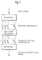
- a method of reducing noise in a time-varying signal comprising the steps of; converting the signal into a plurality of signals representing the magnitude of spectral components of the signal, processing each such signal so that low magnitude spectral components are attenuated relative to high magnitude spectral components, leaving the relationship between such high magnitude spectral components undistorted; and converting the signals thus processed so as to produce a reconstituted time-varying signal having an attenuated noise content.
- a signal which includes noise is received and resolved into a series of signals representing the magnitude of the various components present; this first conversion operation could for example simply comprise filtering the signal through a plurality of parallel band pass filters, but will preferably comprise performing a one dimensional or complex transform operation such as the Discrete Fourier transform (DFT) or the Discrete Cosine Transform (DCT) on frames of samples of the signal.
- DFT Discrete Fourier transform
- DCT Discrete Cosine Transform
- the transform operation may be performed by a suitably programmed general purpose computer, or by separate conversion means such as one of the many dedicated Fast Fourier Transform chip packages currently available.
- the output may comprise parallel signals, as indicated, or these may be multiplexed into serial frames of spectral component data. These data are then processed in a manner which attenuates low magnitude spectral components relative to high magnitude spectral components.
- the processing may be simply achieved by providing an element with a non-linear transfer characteristic (as hereinafter described); if the output data from the first conversion comprises a number of parallel analogue representations then a bank of such elements may be provided.
- the output from the first conversion stage is in digital form, it may readily be processed by general-purpose or dedicated digital data processing means programmed to provide a non-linear response, as hereinafter described, for example by providing a look-up table of output levels for given inputs or a polynomial approximating to the desired characteristic.
- the non-linear portion of the curve shown in Figure 2a could theoretically follow any smooth curve between a straight line with unity slope and a vertical straight line, it will always be a compromise between these extremes, as the first is ineffective and the second (which corresponds to gating in the frequency domain) will generally introduce unacceptable distortion.
- the processed signal produced by the invention is thus a compromise between a reduced level of noise and an introduced level of distortion, and the acceptability of the result is strongly dependent upon the shape of the nonlinear portion of the transfer characteristic, and on the position of the knee region relative to the signal level.
- the shape of the non-linear portion at very low input levels is not particularly important, provided it continues to have a positive slope; the important features of the characteristic as a whole are that above the knee there is a linear portion so that the harmonic relationship of components above this level are undisturbed, that the non-linear portion should fall away steeply enough to attenuate noise below the knee region, and that the knee region itself should be a smooth curve so that the listener does not perceive any significant difference as a spectral component moves through the knee region with time.
- Figure 2b shows an extreme example of a characteristic according to the invention in which on the log/log axes the non-linear portion has a slope of approximately 10 below the knee region down to the limit of audibility (labelled 'OdB').
- Such a characteristic may be derived, for example, by iterative techniques. Equally, the production of an analogue device having such a transfer function is straightforward to one skilled in the art.
- the transfer function of the processing means must be nonlinear with regard to the peak or average value of each component, rather than to its instantaneous value, or the signal will be distorted; the processing means is thus akin to an audio compander.
- the signals representing the spectral components are then reconverted back to an intelligible time-varying signal by a second conversion stage which simply performs the inverse operation of the first conversion stage.
- the second conversion performs the Inverse Discrete Fourier Transform (IDFT).
- IDFT Inverse Discrete Fourier Transform
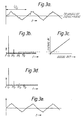
- an input signal illustrated in this case by a triangular wave for simplicity is corrupted by random noise (see Figure 3a).
- the input is resolved into its spectral components, so that for the triangular signal the signal power is concentrated in spectral components at odd multiples of the fundamental frequency of the signal.
- the magnitude of the noise signal in any frequency interval is (for white noise) proportional to the width of that frequency interval, so that the noise power is spread over the spectrum.
- the second conversion stage will then reconstruct a time-domain signal as indicated in Figure 3e, with the noise level strongly reduced, and some minor distortion of the signal produced by the attenuation of higher harmonics of the signal.
- each stage is performed by discrete means.
- the first conversion stage is effected by conversion means 1, which comprises a Fast Fourier Transform device of known type.
- conversion means 1 which comprises a Fast Fourier Transform device of known type.
- Such a device is arranged to receive data input in frames of sampled values; for a speech signal, the length of such a frame should at any rate be shorter than the length of a syllable, and to maintain accuracy should preferably be as short as possible (a further factor is the possibility that unacceptable delays may be introduced by long frames).
- to obtain a reasonable transform it is desirable to sample a large number of points which requires fairly long frames; in practice, frames of between 128 and 1024 points have been found practicable.
- the sampled frame is in effect the product of multiplying the input signal with a rectangular window function having a value of 1 during the sampling period and 0 before and afterwards.
- conversion means 1 includes window function means 1a, which multiplies received data points in a frame by windowing coefficients; preferably, a Hanning function is employed.
- Figure 5 illustrates the general form of such a function.
- Each such windowed frame is received by the transform means which executes a Fast Fourier Transform upon the data in known fashion and produces a number of spectral component signals (the Fourier coefficients), the number being governed by the number of sample data in each frame.
- spectral components which will usually comprise frames of digital samples, are then passed to non-linear processing means 2 which may be provided for example by using a look-up table, and are either (if above the knee region of the characteristic) passed linearly or (if below the knee region of the characteristic) strongly relatively attenuated as described above.
- the frames of processed spectral components are then passed to the second conversion means 3, which executes the Inverse Fast Fourier Transform to reconstitute a time-domain signal.
- the second conversion means 3 includes overlapping means 3a, such as a pair of overlapped data buffers 3b, 3c and an adder 3d, which produce frames of output data with some degree of overlap .
- overlapping means 3a such as a pair of overlapped data buffers 3b, 3c and an adder 3d, which produce frames of output data with some degree of overlap .
- the degree of overlapping necessary and desirable depends on the shape of the window function, and varies from zero in the case of a rectangular window, upwards. In the case of a Hanning function, an overlap of 50% is found particularly effective.
- Figure 6 shows the effect of overlapping by 50% of a frame.
- the amplitude of each output frame 1,2,3 produced by buffer 3b is multiplied by the window function so that there is an audible modulation at frame frequency.
- Buffer 3c produces an output of frames 1,2,3 but delayed by n samples (in other words 50% of the length of each frame).
- Adder 3d adds the outputs of buffers 3b and 3c together, in other words adds to each sample i k produced by buffer 3b, the corresponding sample i k-n produced by buffer 3c, to produce overlapped output frames I,II,III.
- window function means 1a and overlapping means 3a might be included within conversion means 1 and 3 respectively as part of a single chip device.
- the level of the signal may vary slowly with time (as in the case of fading of a radio signal, for example) and, independently, the noise level may also vary. In some cases, the two will vary together (as, for example, when an already noisy signal is subject to fading). For the invention to work effectively, it is desirable that most of the signal should remain above the knee region of the characteristic (and the knee region should remain above the noise level), and so some means of positioning the signal relative to the knee region is necessary (although it will be appreciated that the characteristic could itself be adjusted instead).
- level adjusting means 4 and level restoring means 4a are provided (see Figure 4) which ensure that the signal is correctly positioned upon the transfer characteristic of non-linear processing means 2.
- the level adjusting means 4 detects slow changes in the total power of the signal, and amplifies or attenuates the signal to keep the noise spectrum below the knee and most of the signal above the knee.
- level adjusting means 4 sends a control signal to level restoring means 4a so that the processed signal may be restored to its original level.
- the level adjusting means 4 may be an automatic gain control, and the level control signal is an indication of the gain which acts to control the gain of the level restoring means 4a (the response being slow enough to smooth out fluctuations in level caused by, for example, pauses between spoken words).
- the invention is generally most effective with signal-to-noise ratios of above +10dB, and preferably above +18dB, so the automatic gain control (which responds to the level of signal+noise) is effectively responding to the signal level.
- the level adjusting means could alternately measure one or the other separately, although this separation is technically difficult.
- Level adjusting means 4 could equally be placed between the transform means 1 and processing means 2, so as to operate in the frequency domain, and likewise level restoring means 4a could equally be placed between processing means 2 and inverse transform means 3. In this case, an estimation of signal level can be made as before by examining the magnitude of the largest transform coefficients (which should usually represent signal terms).
- level restoring means 4a It is also possible to omit level restoring means 4a, if a constant level output signal is acceptable.
- a second embodiment of the invention available knowledge about the spectral position of signal data may be utilized to further enhance the noise reduction capability of the invention.
- Human speech consists of a mixture of "voiced” and “unvoiced” sounds, depending on the presence or absence of glottal action. In most cases these waveforms are processed by the vocal tract, which, being tubelike, gives rise to spectral enhancement in certain bands of frequencies; these enhancements are known as 'formants'.
- the spectral position of each formant varies between individuals, and further varies while an individual is speaking.
- a speech signal is level adjusted, windowed and transformed as previously described.
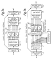
- the spectral component signals are then passed to processing means 2, which assigns different component signals to processing elements 2a, 2b, etc., having different characteristics.
- processing means 2 assigns different component signals to processing elements 2a, 2b, etc., having different characteristics.
- the spectral component signals form a spatially separated series of signals, then signals are physically connected directly to processing elements 2a, 2b etc.
- Element 2a having a very non-linear characteristic, is used to process signals in bands where speech components are statistically rare (noise bands) and element 2b, having a less non-linear characteristic, is employed to process signals in bands where formants are commonly found (speech bands).
- processing means 2 may include a demultiplexer (not shown) to assign the spectral component signals to discrete elements 2a, 2b etc, or a single processing element may be used and its characteristic controlled by control means (not shown) within the processing means 2, so that it exhibits the required predetermined characteristic for each spectral component signal.
- the processed signals are then retransformed and overlapped by second conversion means 3, and their level restored by level restoring means 4a, as described previously.
- means are arranged to detect the time-averaged positions of signal bands and non-signal bands for each call over the initial part of the signal (for example the first few seconds of a phone call), and the output of such means is then used to assign the spectral components to processing elements as before for the duration of the call; this embodiment is therefore capable of adapting to different callers.
- the incoming signal is windowed and transformed as previously described.
- the spectral component signals are then passed to processing means 2, which assigns component signals to processing elements 2a, 2b, etc., having different characteristics, and the separately processed components are then recombined, retransformed and overlapped as previously described by conversion means 3.
- the processing means 2 may include assignment means 20 capable of routing spectral component signals to different processing elements 2a, 2b, etc., in accordance with assignment control signals as shown, or alternatively the processing means 2 may comprise one or a plurality of processing elements with characteristics which may be varied in accordance with assignment control signals.
- the assignment control signals are here provided by averaging means 5, which derive time-averaged information on the positions of formant bands from the output of transform means 1 over the first part of a call and then transmit assignment control signals to processing means 2 to fix for the rest of the call the processing which each spectral component will undergo.
- the averaging means 5 could form part of the processing means.
- data representing respectively the population-averaged or time-averaged likely positions of the speech formant bands is used to fix the processing applied to spectral components either for the duration of the call or for a relatively long re-adaptation period.
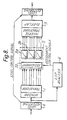
- a means for continuously tracking the positions of the formant bands during a call as illustrated in Figure 8.
- This enables a much closer and more rapid matching of the processing elements with the formant bands and corresponding more effective noise reduction, since noise outside the formant band can be virtually eliminated.
- the characteristics of the processing elements may be graduated between formant and non-formant regions, so as to produce a smooth transition. The more the available data on the shape of the formant band, the more effective is the matching of the processing means.
- One technique which may be employed is the 'Line Spectral Pair' or LSP technique which can provide an estimate of both formant frequency and formant width information if a filter of suitable order is employed.
- references to speech signals above apply equally to any type of signal having a similar spectral content, and that the invention is applicable also to voiceband data signalling.
- a signal for example, a speech signal
- a signal is decomposed into its spectral components at a transmitter, representations of the spectral components are transmitted to a receiver, and the original signal is there reconstituted.
- the invention described above is equally applicable to this class of coding schemes, to remove or reduce any broadband noise which accompanies the input signal (for example, broadband background noise in a speech system).
- Such implementations merely constitute positioning the transmission link between the non-linear processing stage and one of the transform stages; in a first such embodiment, an input signal is transform coded and the transform coefficients thus produced are processed according to one of the methods described above at the transmitter, the processed coefficients then being transmitted to a receiver of conventional type which affects the inverse transform to reconstitute the signal.
- the transform coder at the transmitter is of conventional type, and at the receiver the received transform coefficients are subjected to a non-linear processing stage as described above, prior to the inverse transform operation to reconstitute the original signal.
- each step may be performed by a suitably programmed digital data processing means.
- DSP Digital Signal Processing
Landscapes
- Engineering & Computer Science (AREA)
- Computational Linguistics (AREA)
- Quality & Reliability (AREA)
- Signal Processing (AREA)
- Health & Medical Sciences (AREA)
- Audiology, Speech & Language Pathology (AREA)
- Human Computer Interaction (AREA)
- Physics & Mathematics (AREA)
- Acoustics & Sound (AREA)
- Multimedia (AREA)
- Noise Elimination (AREA)
- Tone Control, Compression And Expansion, Limiting Amplitude (AREA)
Claims (21)
- Rauschreduktionsvorrichtung bestehend aus folgenden Komponenten:- eine erste Umwandlungseinrichtung (1) zum Empfangen eines zeitvariablen Signals und zum Bilden von Ausgangssignalen aus diesem Signal, wobei die Ausgangssignale die Größe von Spektralkomponenten der Ausgangssignale darstellen;- eine Bearbeitungseinrichtung (2) zum Empfangen des Ausgangs der ersten Umwandlungseinrichtung (1), wobei die Bearbeitungseinrichtung (2) eine nicht-lineare Transfercharakteristik in der Weise aufweist, daß Eingänge geringer Größe relativ zu Eingängen hoher Größe gedämpft werden, wobei die Transfercharakteristik weiterhin im wesentlichen linear für Spektralkomponenten hoher Größe ist und nicht-linear für Spektralkomponenten geringer Größe und- eine zweite Umwandlungseinrichtung (3) zum Empfangen des Ausgangs der Bearbeitungseinrichtung (2) und zum Wiederherstellen eines zeitvariablen Signals daraus, dadurch gekennzeichnet, daß die Durchshnittssteigung im nicht-linearen Bereich, dargestellt auf identisch logarithmischen Achsen, nicht den Wert 10 bei detektierbaren Signalpegeln übersteigt.
- Vorrichtung nach Anspruch 1, wobei der Übergang von dem linearen zu dem nicht linearen Bereich der Charakteristik graduell ist und im wesentlichen keine Diskontinuitäten in der Steigung aufweist.
- Vorrichtung nach Anspruch 1, wobei die erste Umwandlungseinrichtung (1) angeordnet ist, um das zeitvariable Signal in Rahmen zu empfangen und auf die Rahmen eine eindimensionale oder komplexe Transformation anzuwenden, wobei deren Ausgangssignale Transformationskoeffizienten sind und wobei eine zweite Umwandlungseinrichtung (3) im Betrieb vorgesehen ist, um die Inverse der Transformation auf die bearbeiteten Transformationskoeffizienten anzuwenden.
- Vorrichtung nach Anspruch 3, in dem die Transformation eine schnelle
- Vorrichtung nach einem der Ansprüche 3 oder 4, wobei die erste Umwandlungseinrichtung (1) angeordnet ist, um jeden der Rahmen durch eine Fensterfunktion vor der Transformation des Rahmens zu multiplizieren.
- Vorrichtung nach Anspruch 5, wobei die zweite Umwandlungseinrichtung (3) angeordnet ist, um aufeinanderfolgende Rahmen zu überlappen.
- Vorrichtung nach einem der vorstehenden Ansprüche, wobei die Bearbeitungsvorrichtung (2) angeordnet ist (2a, b), um eine Vielzahl von unterschiedlichen Transfercharakteristiken anzuwenden, die Spektralkomponentensignalen zugeordnet sind, die unterschiedlichen Abschnitten des Frequenzspektrums entsprechen.
- Vorrichtung nach Anspruch 7, wobei die Frequenzzuordnung der unterschiedlichen Transfercharakteristiken vorbestimmt ist.
- Vorrichtung nach Anspruch 8, wobei die Vorrichtung eine Einrichtung (5) aufweist, die angeordnet ist, um eine zeitlich gemittelte Spektralverteilung der Komponenten des Signals abzuleiten und um die Frequenzzuordnung unterschiedlicher Transfercharakteristiken dementsprechend periodisch zu bestimmen.
- Vorrichtung nach Anspruch 7, in der eine Einrichtung (6) vorgesehen ist, die angeordnet ist, um die Spektralpositionen der Komponenten des Signals zu erkennen und die Frequenzzuordnung unterschiedlicher Charakteristiken dementsprechend zu variieren.
- Vorrichtung nach Anspruch 10, wobei die Erkennungseinrichtung (6) ein Linien-Spektral-Paar-Analysen-Verfahren anwendet.
- Vorrichtung nach einem der vorstehenden Ansprüche, wobei die Vorrichtung eine Pegeljustiereinrichtung (4) aufweist, die angepaßt ist, den Pegel der von der Bearbeitungseinrichtung (2) empfangenen Signale in der Weise anzupassen, daß der Pegel wenigstens einiger Spektralkomponenten darin innerhalb eines vorbestimmten Verhältnisses zu der oder zu jedem Transfercharakteristikum der Bearbeitungseinrichtung aufrechterhalten wird.
- Vorrichtung nach Anspruch 12, wobei die Pegeljustiereinrichtung (4) eine Verstärkungsautomatikschaltung ist, die in Abhängigkeit des Durchschnittspegels des zeitvariablen Signals arbeitet.
- Vorrichtung nach einem der Ansprüche 1 bis 11, wobei die Vorrichtung eine Einrichtung aufweist, die angepaßt ist, um das oder jedes Charakteristikum der Bearbeitungseinrichtung in der Weise zu skalieren, daß der Pegel wenigstens einiger Spektralkomponenten innerhalb eines vorbestimmten Verhältnisses mit dem oder mit jedem Transfercharakteristikum aufrechterhalten wird.
- Teilnehmertelefonvorrichtung einschließlich einer Rauschredukionsvorrichtung gemäß einem der vorstehenden Ansprüche.
- Verfahren zum Unterdrücken von Rauschen in einem zeitvariablen Signal, das die folgenden Schritte aufweist:- Umwandeln des Signals in eine Vielzahl von Signalen, die die Größe von Spektralkomponenten des Signals darstellen;- Bearbeiten eines jeden derartigen Spektralkomponentensignals mittels einer nicht-linearen Transfercharakteristik, wobei die Transfercharakteristik im wesentlichen linear für Spektralkomponenten hoher Größe und nicht-linear für Spektralkomponenten geringer Größe in der Weise ist, daß Spektralkomponenten geringer Größe bezüglich Spektralkomponenten hoher Größe gedämpft werden, wobei das Verhältnis zwischen solchen Spektralkomponenten hoher Größe ungestört bleibt; und- Umwandeln der so bearbeiteten Signale, um ein wiederhergestelltes zeitvariables Signal mit einem gedämpften Rauschinhalt zu bilden, dadurch gekennzeichnet, daß die Durchschnittssteigung der nicht-linearen Region der Transfercharakteristik, dargestellt auf identisch logarithmischen Achsen, nicht den Wert 10 bei detektierbaren Signalpegeln überschreitet.
- Verfahren zum Unterdrücken von Rauschen nach Anspruch 16, wobei der Übergang zwischen linearer und nicht-linearer Bearbeitung graduell und im wesentlichen ohne Diskontinuitäten in der Steigung verläuft.
- Verfahren zum Reduzieren von Rauschen nach Anspruch 16 oder 17, wobei Signale, die unterschiedliche Spektralkomponenten darstellen, in
- Transformationskodiersystem einschließlich einer Rauschreduktionsvorrichtung nach einem der Ansprüche 1-14.
- Sender für ein System nach Anspruch 19, das eine solche Rauschreduktionsvorrichtung aufweist.
- Empfänger für ein System nach Anspruch 19, das eine solche Rauschreduktionsvorrichtung aufweist.
Priority Applications (1)
| Application Number | Priority Date | Filing Date | Title |
|---|---|---|---|
| AT89901730T ATE101767T1 (de) | 1988-01-18 | 1989-01-18 | Stoerunterdrueckung. |
Applications Claiming Priority (2)
| Application Number | Priority Date | Filing Date | Title |
|---|---|---|---|
| GB888801014A GB8801014D0 (en) | 1988-01-18 | 1988-01-18 | Noise reduction |
| GB8801014 | 1988-01-18 |
Publications (2)
| Publication Number | Publication Date |
|---|---|
| EP0367803A1 EP0367803A1 (de) | 1990-05-16 |
| EP0367803B1 true EP0367803B1 (de) | 1994-02-16 |
Family
ID=10630116
Family Applications (1)
| Application Number | Title | Priority Date | Filing Date |
|---|---|---|---|
| EP89901730A Expired - Lifetime EP0367803B1 (de) | 1988-01-18 | 1989-01-18 | Störunterdrückung |
Country Status (8)
| Country | Link |
|---|---|
| US (1) | US5133013A (de) |
| EP (1) | EP0367803B1 (de) |
| JP (1) | JP3204501B2 (de) |
| CA (1) | CA1332626C (de) |
| DE (1) | DE68913139T2 (de) |
| GB (2) | GB8801014D0 (de) |
| HK (1) | HK121496A (de) |
| WO (1) | WO1989006877A1 (de) |
Families Citing this family (56)
| Publication number | Priority date | Publication date | Assignee | Title |
|---|---|---|---|---|
| US5479560A (en) * | 1992-10-30 | 1995-12-26 | Technology Research Association Of Medical And Welfare Apparatus | Formant detecting device and speech processing apparatus |
| GB2272615A (en) * | 1992-11-17 | 1994-05-18 | Rudolf Bisping | Controlling signal-to-noise ratio in noisy recordings |
| ES2137355T3 (es) * | 1993-02-12 | 1999-12-16 | British Telecomm | Reduccion de ruido. |
| US5432859A (en) * | 1993-02-23 | 1995-07-11 | Novatel Communications Ltd. | Noise-reduction system |
| US5533133A (en) * | 1993-03-26 | 1996-07-02 | Hughes Aircraft Company | Noise suppression in digital voice communications systems |
| EP0707763B1 (de) * | 1993-07-07 | 2001-08-29 | Picturetel Corporation | Verringerung des hintergrundrauschens zur sprachverbesserung |
| US5651071A (en) * | 1993-09-17 | 1997-07-22 | Audiologic, Inc. | Noise reduction system for binaural hearing aid |
| JPH07193548A (ja) * | 1993-12-25 | 1995-07-28 | Sony Corp | 雑音低減処理方法 |
| GB9405211D0 (en) * | 1994-03-17 | 1994-04-27 | Deas Alexander R | Noise cancellation apparatus |
| GB9414484D0 (en) * | 1994-07-18 | 1994-09-21 | Marconi Gec Ltd | An apparatus for cancelling vibrations |
| EP0693747A3 (de) * | 1994-07-18 | 1997-12-29 | Gec-Marconi Limited | Anordnung zur Schwingungsunterdrückung |
| JPH08102687A (ja) * | 1994-09-29 | 1996-04-16 | Yamaha Corp | 音声送受信方式 |
| ES2144651T3 (es) * | 1994-12-15 | 2000-06-16 | British Telecomm | Tratamiento de voz. |
| US5774846A (en) * | 1994-12-19 | 1998-06-30 | Matsushita Electric Industrial Co., Ltd. | Speech coding apparatus, linear prediction coefficient analyzing apparatus and noise reducing apparatus |
| SE505156C2 (sv) * | 1995-01-30 | 1997-07-07 | Ericsson Telefon Ab L M | Förfarande för bullerundertryckning genom spektral subtraktion |
| US6263307B1 (en) * | 1995-04-19 | 2001-07-17 | Texas Instruments Incorporated | Adaptive weiner filtering using line spectral frequencies |
| JP3591068B2 (ja) * | 1995-06-30 | 2004-11-17 | ソニー株式会社 | 音声信号の雑音低減方法 |
| FI100840B (fi) | 1995-12-12 | 1998-02-27 | Nokia Mobile Phones Ltd | Kohinanvaimennin ja menetelmä taustakohinan vaimentamiseksi kohinaises ta puheesta sekä matkaviestin |
| SE9700772D0 (sv) * | 1997-03-03 | 1997-03-03 | Ericsson Telefon Ab L M | A high resolution post processing method for a speech decoder |
| AU764316C (en) * | 1997-04-16 | 2004-06-24 | Emma Mixed Signal C.V. | Apparatus for noise reduction, particulary in hearing aids |
| ATE423434T1 (de) * | 1997-04-16 | 2009-03-15 | Emma Mixed Signal Cv | Verfahren und vorrichtung zur rauschverminderung, insbesondere bei hörhilfegeräten |
| US6510408B1 (en) * | 1997-07-01 | 2003-01-21 | Patran Aps | Method of noise reduction in speech signals and an apparatus for performing the method |
| GB2336978B (en) * | 1997-07-02 | 2000-11-08 | Simoco Int Ltd | Method and apparatus for speech enhancement in a speech communication system |
| GB9714001D0 (en) * | 1997-07-02 | 1997-09-10 | Simoco Europ Limited | Method and apparatus for speech enhancement in a speech communication system |
| US5913187A (en) * | 1997-08-29 | 1999-06-15 | Nortel Networks Corporation | Nonlinear filter for noise suppression in linear prediction speech processing devices |
| US6157908A (en) * | 1998-01-27 | 2000-12-05 | Hm Electronics, Inc. | Order point communication system and method |
| US6415253B1 (en) * | 1998-02-20 | 2002-07-02 | Meta-C Corporation | Method and apparatus for enhancing noise-corrupted speech |
| AU721270B2 (en) * | 1998-03-30 | 2000-06-29 | Mitsubishi Denki Kabushiki Kaisha | Noise reduction apparatus and noise reduction method |
| US6453289B1 (en) * | 1998-07-24 | 2002-09-17 | Hughes Electronics Corporation | Method of noise reduction for speech codecs |
| US6328507B1 (en) | 1998-08-04 | 2001-12-11 | Shoda Iron Works Co., Ltd | Working table apparatus for a cutting machine tool |
| US6519486B1 (en) | 1998-10-15 | 2003-02-11 | Ntc Technology Inc. | Method, apparatus and system for removing motion artifacts from measurements of bodily parameters |
| US7991448B2 (en) * | 1998-10-15 | 2011-08-02 | Philips Electronics North America Corporation | Method, apparatus, and system for removing motion artifacts from measurements of bodily parameters |
| US6993480B1 (en) | 1998-11-03 | 2006-01-31 | Srs Labs, Inc. | Voice intelligibility enhancement system |
| US6604071B1 (en) * | 1999-02-09 | 2003-08-05 | At&T Corp. | Speech enhancement with gain limitations based on speech activity |
| JP3454190B2 (ja) * | 1999-06-09 | 2003-10-06 | 三菱電機株式会社 | 雑音抑圧装置および方法 |
| US6738445B1 (en) | 1999-11-26 | 2004-05-18 | Ivl Technologies Ltd. | Method and apparatus for changing the frequency content of an input signal and for changing perceptibility of a component of an input signal |
| US6931292B1 (en) | 2000-06-19 | 2005-08-16 | Jabra Corporation | Noise reduction method and apparatus |
| US20030216907A1 (en) * | 2002-05-14 | 2003-11-20 | Acoustic Technologies, Inc. | Enhancing the aural perception of speech |
| US7292985B2 (en) * | 2004-12-02 | 2007-11-06 | Janus Development Group | Device and method for reducing stuttering |
| US7459962B2 (en) * | 2006-07-26 | 2008-12-02 | The Boeing Company | Transient signal detection algorithm using order statistic filters applied to the power spectral estimate |
| US7672842B2 (en) * | 2006-07-26 | 2010-03-02 | Mitsubishi Electric Research Laboratories, Inc. | Method and system for FFT-based companding for automatic speech recognition |
| JP4827661B2 (ja) * | 2006-08-30 | 2011-11-30 | 富士通株式会社 | 信号処理方法及び装置 |
| US7925307B2 (en) * | 2006-10-31 | 2011-04-12 | Palm, Inc. | Audio output using multiple speakers |
| US8311590B2 (en) * | 2006-12-05 | 2012-11-13 | Hewlett-Packard Development Company, L.P. | System and method for improved loudspeaker functionality |
| US8050434B1 (en) | 2006-12-21 | 2011-11-01 | Srs Labs, Inc. | Multi-channel audio enhancement system |
| WO2009017392A1 (en) * | 2007-07-27 | 2009-02-05 | Vu Medisch Centrum | Noise suppression in speech signals |
| JP5012995B2 (ja) * | 2008-03-24 | 2012-08-29 | 株式会社Jvcケンウッド | オーディオ信号処理装置及びオーディオ信号処理方法 |
| EP2347556B1 (de) * | 2008-09-19 | 2012-04-04 | Dolby Laboratories Licensing Corporation | Upstream-signalverarbeitung für client-einrichtungen in einem drahtlosen kleinzellen-netz |
| KR101547344B1 (ko) * | 2008-10-31 | 2015-08-27 | 삼성전자 주식회사 | 음성복원장치 및 그 방법 |
| CN101986386B (zh) * | 2009-07-29 | 2012-09-26 | 比亚迪股份有限公司 | 一种语音背景噪声的消除方法和装置 |
| CA2923888C (en) * | 2013-09-12 | 2018-11-27 | Saudi Arabian Oil Company | Dynamic threshold methods, systems, computer readable media, and program code for filtering noise and restoring attenuated high-frequency components of acoustic signals |
| US9800276B2 (en) | 2013-10-08 | 2017-10-24 | Cisco Technology, Inc. | Ingress cancellation tachometer |
| WO2017143334A1 (en) * | 2016-02-19 | 2017-08-24 | New York University | Method and system for multi-talker babble noise reduction using q-factor based signal decomposition |
| EP3429230A1 (de) * | 2017-07-13 | 2019-01-16 | GN Hearing A/S | Hörgerät und verfahren mit nichtintrusiver vorhersage der sprachverständlichkeit |
| US11170799B2 (en) * | 2019-02-13 | 2021-11-09 | Harman International Industries, Incorporated | Nonlinear noise reduction system |
| CN110931035B (zh) * | 2019-12-09 | 2023-10-10 | 广州酷狗计算机科技有限公司 | 音频处理方法、装置、设备及存储介质 |
Citations (3)
| Publication number | Priority date | Publication date | Assignee | Title |
|---|---|---|---|---|
| US4221934A (en) * | 1979-05-11 | 1980-09-09 | Rca Corporation | Compandor for group of FDM signals |
| DE3029441A1 (de) * | 1980-08-02 | 1982-03-04 | Licentia Patent-Verwaltungs-Gmbh, 6000 Frankfurt | Signaluebertragungsschaltung mit steuerbarem uebertragungsmass |
| US4544916A (en) * | 1982-08-31 | 1985-10-01 | At&T Bell Laboratories | Digital code translator |
Family Cites Families (6)
| Publication number | Priority date | Publication date | Assignee | Title |
|---|---|---|---|---|
| US3989897A (en) * | 1974-10-25 | 1976-11-02 | Carver R W | Method and apparatus for reducing noise content in audio signals |
| US4630304A (en) * | 1985-07-01 | 1986-12-16 | Motorola, Inc. | Automatic background noise estimator for a noise suppression system |
| US4897878A (en) * | 1985-08-26 | 1990-01-30 | Itt Corporation | Noise compensation in speech recognition apparatus |
| US4658426A (en) * | 1985-10-10 | 1987-04-14 | Harold Antin | Adaptive noise suppressor |
| US4829578A (en) * | 1986-10-02 | 1989-05-09 | Dragon Systems, Inc. | Speech detection and recognition apparatus for use with background noise of varying levels |
| US4887299A (en) * | 1987-11-12 | 1989-12-12 | Nicolet Instrument Corporation | Adaptive, programmable signal processing hearing aid |
-
1988
- 1988-01-18 GB GB888801014A patent/GB8801014D0/en active Pending
-
1989
- 1989-01-18 JP JP50154289A patent/JP3204501B2/ja not_active Expired - Fee Related
- 1989-01-18 WO PCT/GB1989/000049 patent/WO1989006877A1/en not_active Ceased
- 1989-01-18 US US07/401,455 patent/US5133013A/en not_active Expired - Fee Related
- 1989-01-18 CA CA000588588A patent/CA1332626C/en not_active Expired - Fee Related
- 1989-01-18 DE DE68913139T patent/DE68913139T2/de not_active Expired - Fee Related
- 1989-01-18 GB GB8918755A patent/GB2220330B/en not_active Expired
- 1989-01-18 EP EP89901730A patent/EP0367803B1/de not_active Expired - Lifetime
-
1996
- 1996-07-11 HK HK121496A patent/HK121496A/xx not_active IP Right Cessation
Patent Citations (3)
| Publication number | Priority date | Publication date | Assignee | Title |
|---|---|---|---|---|
| US4221934A (en) * | 1979-05-11 | 1980-09-09 | Rca Corporation | Compandor for group of FDM signals |
| DE3029441A1 (de) * | 1980-08-02 | 1982-03-04 | Licentia Patent-Verwaltungs-Gmbh, 6000 Frankfurt | Signaluebertragungsschaltung mit steuerbarem uebertragungsmass |
| US4544916A (en) * | 1982-08-31 | 1985-10-01 | At&T Bell Laboratories | Digital code translator |
Non-Patent Citations (1)
| Title |
|---|
| T.Eger et al.: "A nonlinear spectrum processing technique for speech enhancement", 1983 ICASSP Proceedings. p. 18A1.1.-18A.1.4. * |
Also Published As
| Publication number | Publication date |
|---|---|
| JP3204501B2 (ja) | 2001-09-04 |
| JPH02503256A (ja) | 1990-10-04 |
| GB8918755D0 (en) | 1989-10-04 |
| EP0367803A1 (de) | 1990-05-16 |
| WO1989006877A1 (en) | 1989-07-27 |
| DE68913139D1 (de) | 1994-03-24 |
| HK121496A (en) | 1996-07-19 |
| GB2220330B (en) | 1992-03-25 |
| DE68913139T2 (de) | 1994-06-23 |
| US5133013A (en) | 1992-07-21 |
| GB2220330A (en) | 1990-01-04 |
| CA1332626C (en) | 1994-10-18 |
| GB8801014D0 (en) | 1988-02-17 |
Similar Documents
| Publication | Publication Date | Title |
|---|---|---|
| EP0367803B1 (de) | Störunterdrückung | |
| US7174291B2 (en) | Noise suppression circuit for a wireless device | |
| US8249861B2 (en) | High frequency compression integration | |
| US7366294B2 (en) | Communication system tonal component maintenance techniques | |
| US8219389B2 (en) | System for improving speech intelligibility through high frequency compression | |
| US8010355B2 (en) | Low complexity noise reduction method | |
| US7742914B2 (en) | Audio spectral noise reduction method and apparatus | |
| US8015002B2 (en) | Dynamic noise reduction using linear model fitting | |
| US8560308B2 (en) | Speech sound enhancement device utilizing ratio of the ambient to background noise | |
| US20070232257A1 (en) | Noise suppressor | |
| KR100876794B1 (ko) | 이동 단말에서 음성의 명료도 향상 장치 및 방법 | |
| WO1997022116A2 (en) | A noise suppressor and method for suppressing background noise in noisy speech, and a mobile station | |
| KR950022572A (ko) | 원음성 신호처리 방법 및 전화기 세트 | |
| US7917359B2 (en) | Noise suppressor for removing irregular noise | |
| US4630300A (en) | Front-end processor for narrowband transmission | |
| US20100278353A1 (en) | System and Method For Intelligibility Enhancement of Audio Information | |
| US20060089836A1 (en) | System and method of signal pre-conditioning with adaptive spectral tilt compensation for audio equalization | |
| US8437386B2 (en) | Communication system | |
| EP1748426A2 (de) | Verfahren und Vorrichtung zur adaptiven Rauschunterdrückung | |
| Tzur et al. | Sound equalization in a noisy environment | |
| JPH05137191A (ja) | ハウリング抑制装置 | |
| WO2001065543A1 (en) | Compensation for linear filtering using frequency weighting factors | |
| Popov et al. | Changing the Properties of the Audio Broadcast Signal in Adaptive Transmission Channels | |
| Nohara et al. | A noise suppression system for FM radio receiver |
Legal Events
| Date | Code | Title | Description |
|---|---|---|---|
| PUAI | Public reference made under article 153(3) epc to a published international application that has entered the european phase |
Free format text: ORIGINAL CODE: 0009012 |
|
| 17P | Request for examination filed |
Effective date: 19890821 |
|
| AK | Designated contracting states |
Kind code of ref document: A1 Designated state(s): AT BE CH DE FR GB IT LI LU NL SE |
|
| 17Q | First examination report despatched |
Effective date: 19920512 |
|
| GRAA | (expected) grant |
Free format text: ORIGINAL CODE: 0009210 |
|
| RBV | Designated contracting states (corrected) |
Designated state(s): AT BE CH DE FR IT LI LU NL SE |
|
| AK | Designated contracting states |
Kind code of ref document: B1 Designated state(s): AT BE CH DE FR IT LI LU NL SE |
|
| PG25 | Lapsed in a contracting state [announced via postgrant information from national office to epo] |
Ref country code: LI Effective date: 19940216 Ref country code: CH Effective date: 19940216 Ref country code: BE Effective date: 19940216 Ref country code: AT Effective date: 19940216 |
|
| REF | Corresponds to: |
Ref document number: 101767 Country of ref document: AT Date of ref document: 19940315 Kind code of ref document: T |
|
| ITF | It: translation for a ep patent filed | ||
| REF | Corresponds to: |
Ref document number: 68913139 Country of ref document: DE Date of ref document: 19940324 |
|
| REG | Reference to a national code |
Ref country code: CH Ref legal event code: PL |
|
| ET | Fr: translation filed | ||
| PLBE | No opposition filed within time limit |
Free format text: ORIGINAL CODE: 0009261 |
|
| STAA | Information on the status of an ep patent application or granted ep patent |
Free format text: STATUS: NO OPPOSITION FILED WITHIN TIME LIMIT |
|
| EAL | Se: european patent in force in sweden |
Ref document number: 89901730.5 |
|
| PG25 | Lapsed in a contracting state [announced via postgrant information from national office to epo] |
Ref country code: LU Free format text: LAPSE BECAUSE OF NON-PAYMENT OF DUE FEES Effective date: 19950131 |
|
| 26N | No opposition filed | ||
| PGFP | Annual fee paid to national office [announced via postgrant information from national office to epo] |
Ref country code: FR Payment date: 20011210 Year of fee payment: 14 |
|
| PGFP | Annual fee paid to national office [announced via postgrant information from national office to epo] |
Ref country code: SE Payment date: 20011218 Year of fee payment: 14 |
|
| PGFP | Annual fee paid to national office [announced via postgrant information from national office to epo] |
Ref country code: NL Payment date: 20011219 Year of fee payment: 14 Ref country code: DE Payment date: 20011219 Year of fee payment: 14 |
|
| PG25 | Lapsed in a contracting state [announced via postgrant information from national office to epo] |
Ref country code: SE Free format text: LAPSE BECAUSE OF NON-PAYMENT OF DUE FEES Effective date: 20030119 |
|
| PG25 | Lapsed in a contracting state [announced via postgrant information from national office to epo] |
Ref country code: NL Free format text: LAPSE BECAUSE OF NON-PAYMENT OF DUE FEES Effective date: 20030801 Ref country code: DE Free format text: LAPSE BECAUSE OF NON-PAYMENT OF DUE FEES Effective date: 20030801 |
|
| EUG | Se: european patent has lapsed | ||
| PG25 | Lapsed in a contracting state [announced via postgrant information from national office to epo] |
Ref country code: FR Free format text: LAPSE BECAUSE OF NON-PAYMENT OF DUE FEES Effective date: 20030930 |
|
| NLV4 | Nl: lapsed or anulled due to non-payment of the annual fee |
Effective date: 20030801 |
|
| REG | Reference to a national code |
Ref country code: FR Ref legal event code: ST |
|
| PG25 | Lapsed in a contracting state [announced via postgrant information from national office to epo] |
Ref country code: IT Free format text: LAPSE BECAUSE OF NON-PAYMENT OF DUE FEES;WARNING: LAPSES OF ITALIAN PATENTS WITH EFFECTIVE DATE BEFORE 2007 MAY HAVE OCCURRED AT ANY TIME BEFORE 2007. THE CORRECT EFFECTIVE DATE MAY BE DIFFERENT FROM THE ONE RECORDED. Effective date: 20050118 |