EP0367836A1 - Fahrbares Röntgendiagnostikgerät mit einer höhenverstellbaren Säule - Google Patents
Fahrbares Röntgendiagnostikgerät mit einer höhenverstellbaren Säule Download PDFInfo
- Publication number
- EP0367836A1 EP0367836A1 EP88117043A EP88117043A EP0367836A1 EP 0367836 A1 EP0367836 A1 EP 0367836A1 EP 88117043 A EP88117043 A EP 88117043A EP 88117043 A EP88117043 A EP 88117043A EP 0367836 A1 EP0367836 A1 EP 0367836A1
- Authority
- EP
- European Patent Office
- Prior art keywords
- column
- ray diagnostic
- diagnostic device
- deflection
- rope
- Prior art date
- Legal status (The legal status is an assumption and is not a legal conclusion. Google has not performed a legal analysis and makes no representation as to the accuracy of the status listed.)
- Granted
Links
- 230000005855 radiation Effects 0.000 claims abstract description 6
- 230000015572 biosynthetic process Effects 0.000 description 1
- 230000000903 blocking effect Effects 0.000 description 1
- 238000010276 construction Methods 0.000 description 1
Images
Classifications
-
- A—HUMAN NECESSITIES
- A61—MEDICAL OR VETERINARY SCIENCE; HYGIENE
- A61B—DIAGNOSIS; SURGERY; IDENTIFICATION
- A61B6/00—Apparatus or devices for radiation diagnosis; Apparatus or devices for radiation diagnosis combined with radiation therapy equipment
- A61B6/44—Constructional features of apparatus for radiation diagnosis
- A61B6/4429—Constructional features of apparatus for radiation diagnosis related to the mounting of source units and detector units
- A61B6/447—Constructional features of apparatus for radiation diagnosis related to the mounting of source units and detector units the source unit or the detector unit being mounted to counterpoise or springs
Definitions
- the invention relates to a mobile X-ray diagnostic device with a height-adjustable column mounted on one side on a chassis, which supports an X-ray emitter and a radiation receiver via a holder.
- Such an X-ray diagnostic device is known for example from DE-PS 1 958 905.
- the height of this X-ray diagnostic device can be adjusted using an electric motor drive.
- the electric motor is supplied with electrical energy from the mains or a battery.
- a line and a power supply connection to which the line leads must be provided for the power supply from the network.
- the chassis of the X-ray diagnostic device must be designed in accordance with the higher weight and dimensions of the rechargeable battery.
- the object of the invention is therefore to carry out an X-ray diagnostic device of the type mentioned at the outset in such a way that height adjustment of the column is easily possible with a simple, space-saving construction without an electric motor drive.
- the object is achieved in that one end of a rope is connected to the column in the region of its lower end and that the rope is guided over a deflection so that it exerts a vertical weight balancing force on the column, which is generated by a spring , which is stretched horizontally in a cantilever of the chassis of the X-ray diagnostic device.
- the advantage of the invention is that the height-adjustable column is height-adjustable and that no electrical energy is necessary for this. This is particularly advantageous when moving the X-ray diagnostic device on a station if the column with the X-ray emitter and the radiation receiver was not moved to the lowest position immediately after an X-ray was taken.
- the cable for energy supply must then be connected to a power supply connection in order to move the column into its lowest position.
- a connection may not be within reach, so that the X-ray diagnostic device must be moved to such a connection before the actual journey can be continued.
- the column in an X-ray diagnostic device according to the invention can be adjusted without the supply of electrical energy.
- a brake is provided for locking the column.
- the column can thus be locked at any point on the adjustment path, in particular when the X-ray diagnostic device tilts.
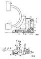
- FIG. 1 shows a mobile x-ray diagnostic device 1 with a holder 2, which can be adjusted in height by means of a column 3 on a chassis, and which have an x-ray emitter 4 and one Radiation receiver 5 carries.
- a rope 7 is fastened in the lower region 6 of the column 3. It is guided via a first deflection 8 with two rollers to a second deflection 9.
- the rope 7 is placed around the deflection 9, which is designed as a spiral drum, and leads from there via a third deflection 10 to a fastening 11 in the lower region of the chassis.
- the third deflection 10 is designed as a roller and is connected to a prestressed spiral spring 13 which is horizontally aligned in the arm 12 of the chassis.
- the spiral 14 of the second deflection 9 is formed in connection with the tensile force of the coil spring 13 so that the force for adjusting the column 3 is uniform over the entire adjustment path S of the column 3. Since the tensile force of the spiral spring 13 changes as a function of its extension A, it is necessary to also change the levers H1, H2 (see also FIG. 2) of the deflection 9 when the column 3 is adjusted so that the torque of the deflection 9 and thus the weight balancing force on the rope 7 is constant. This is achieved by the formation of the spiral 14. When adjusting the column 3 along the adjustment path S, the spiral 14 rotates about the axis of the deflection 9. The cable 7 is guided along the conically shaped drum, the effective levers H1, H2 changing.
- the column 3 is locked by a brake 15, which is shown as an example in FIG. It has a braking element 16 which is pressed via the force of a spiral spring 17 onto a brake disc 18 which is connected to the deflection 9.
- a permanent magnet can also act on the braking element 16.
- the column is locked.
- the brake is released when an electromechanical drive 19, the voltage of a voltage source 20 is supplied via a switch 21.
- the contact pressure of the braking element 16 is released so that the brake disc 18 and thus the deflection 9 is freely adjustable.
- the contact pressure of the braking element 16 can also be released via the actuating means (not shown) on the X-ray diagnostic device 1. In this way, the brake can also be released without the supply of electrical energy.
- a fork-shaped element 22 is adjustably mounted transversely to the brake disc 18 via a bearing 23.
- Recesses 24 are provided on the circumference of the brake disc 18, into which the fork-shaped element 22 engages with one of the legs 25 or 26 when the X-ray diagnostic device 1 is tilted to the side, so that the adjustability of the column 3 is blocked. The blocking is lifted when the chassis of the X-ray diagnostic device 1 is again approximately horizontally aligned.
Landscapes
- Health & Medical Sciences (AREA)
- Life Sciences & Earth Sciences (AREA)
- Medical Informatics (AREA)
- Engineering & Computer Science (AREA)
- Radiology & Medical Imaging (AREA)
- Biomedical Technology (AREA)
- Biophysics (AREA)
- Nuclear Medicine, Radiotherapy & Molecular Imaging (AREA)
- Optics & Photonics (AREA)
- Pathology (AREA)
- Physics & Mathematics (AREA)
- High Energy & Nuclear Physics (AREA)
- Heart & Thoracic Surgery (AREA)
- Molecular Biology (AREA)
- Surgery (AREA)
- Animal Behavior & Ethology (AREA)
- General Health & Medical Sciences (AREA)
- Public Health (AREA)
- Veterinary Medicine (AREA)
- Apparatus For Radiation Diagnosis (AREA)
Abstract
Description
- Die Erfindung betrifft ein fahrbares Röntgendiagnostikgerät mit einer an einem Fahrgestell einseitig gelagerten, höhenverstellbaren Säule, die über eine Halterung einen Röntgenstrahler und einen Strahlenempfänger trägt.
- Ein solches Röntgendiagnostikgerät ist beispielsweise aus der DE-PS 1 958 905 bekannt. Bei diesem Röntgendiagnostikgerät ist die Säule über einen elektromotorischen Antrieb in der Höhe verstellbar.
- Zur Höhenverstellung der Säule ist dem elektromotorischen Antrieb die elektrische Energie aus dem Netz oder eines Akkus zuzuführen. Zur Spannungsversorgung aus dem Netz ist eine Leitung und ein Energieversorgungsanschluß, zu dem die Leitung führt, vorzusehen. Bei der Energieversorgung aus einem Akku ist das Fahrgestell des Röntgendiagnostikgerätes entsprechend dem höheren Gewicht und den Abmessungen des Akkus auszulegen.
- Aufgabe der Erfindung ist es daher, ein Röntgendiagnostikgerät der eingangs genannten Art so auszuführen, daß eine Höhenverstellung der Säule bei einfachem, platzsparendem Aufbau leicht ohne einen elektromotorischen Antrieb möglich ist.
- Die Aufgabe ist erfindungsgemäß dadurch gelöst, daß ein Ende eines Seiles mit der Säule im Bereich ihres unteren Endes verbunden ist und daß das Seil derart über eine Umlenkung geführt ist, so daß es auf die Säule eine vertikale Gewichtsausgleichskraft ausübt, welche von einer Feder erzeugt wird, die horizontal in einem Ausleger des Fahrgestelles des Röntgendiagnostikgerätes gespannt ist.
- Vorteil der Erfindung ist, daß die Säule gewichtsausgeglichen höhenverstellbar ist und daß hierzu keine elektrische Energie notwendig ist. Dies ist insbesondere beim Verfahren des Röntgendiagnostikgerätes auf einer Station vorteilhaft, wenn die Säule mit dem Röntgenstrahler und dem Strahlenempfänger nach dem Anfertigen einer Röntgenaufnahme nicht sofort in die niedrigste Stellung gefahren wurde. Beim Stand der Technik muß dann das Kabel zur Energieversorgung mit einem Energieversorgungsanschluß verbunden werden, um die Säule in ihre unterste Stellung zu fahren. Ein solcher Anschluß ist aber unter Umständen nicht in erreichbarer Nähe, so daß das Röntgendiagnostikgerät zu einem solchen Anschluß gefahren werden muß, bevor die eigentliche Fahrt fortgesetzt werden kann. Dahingegen kann die Säule bei einem Röntgendiagnostikgerät nach der Erfindung ohne das Zuführen von elektrischer Energie verstellt werden.
- Vorteilhaft ist, wenn eine Bremse zum Arretieren der Säule vorgesehen ist. Somit kann die Säule an jeder beliebigen Stelle des Verstellweges arretiert werden, insbesondere dann, wenn das Röntgendiagnostikgerät kippt.
- Weitere Vorteile und Einzelheiten der Erfindung ergeben sich aus der nachfolgenden Beschreibung eines Ausführungsbeispieles anhand der Zeichnung in Verbindung mit den Unteransprüchen. Dabei zeigt die
- Figur 1 ein fahrbares Röntgendiagnostikgerät mit einer höhenverstellbaren Säule nach der Erfindung und
- Figur 2 eine Umlenkung mit einer spiralförmigen Trommel und einer Bremse zum Arretieren der Säule des Röntgendiagnostikgerätes gemäß Figur 1.
- Die Figur 1 zeigt ein fahrbares Röntgendiagnostikgerät 1 mit einer Halterung 2, die über eine Säule 3 an einem Fahrgestell höhenverstellbar ist und die einen Röntgenstrahler 4 und einen Strahlenempfänger 5 trägt. Im unteren Bereich 6 der Säule 3 ist ein Seil 7 befestigt. Es ist über eine erste Umlenkung 8 mit zwei Rollen zu einer zweiten Umlenkung 9 geführt. Das Seil 7 ist um die Umlenkung 9, die als spiralförmige Trommel ausgebildet ist, gelegt und führt von dort über eine dritte Umlenkung 10 zu einer Befestigung 11 im unteren Bereich des Fahrgestelles. Die dritte Umlenkung 10 ist als Rolle ausgebildet und steht mit einer im Ausleger 12 des Fahrgestelles horizontal ausgerichteten vorgespannten Spiralfeder 13 in Verbindung. Durch die gespannte Spiralfeder 13 wirkt eine Zugkraft auf das Seil 7, die die Gewichtskraft der Säule 3 und der Halterung 2 mit dem Röntgenstrahler 4 und dem Strahlenempfänger 5 ausgleicht. Die Spirale 14 der zweiten Umlenkung 9 ist in Verbindung mit der Zugkraft der Spiralfeder 13 so ausgebildet, daß die Kraft zum Verstellen der Säule 3 über den gesamten Verstellweg S der Säule 3 gleichmäßig ist. Da sich die Zugkraft der Spiralfeder 13 in Abhängigkeit von deren Auszug A ändert, ist es notwendig, auch die Hebel H1, H2 (siehe auch Figur 2) der Umlenkung 9 bei einer Verstellung der Säule 3 so zu verändern, daß das Drehmoment der Umlenkung 9 und damit die Gewichtsausgleichskraft auf das Seil 7 konstant ist. Dies wird durch die Ausbildung der Spirale 14 erreicht. Beim Verstellen der Säule 3 längs des Verstellweges S rotiert die Spirale 14 um die Achse der Umlenkung 9. Dabei wird das Seil 7 entlang der konisch ausgebildeten Trommel geführt, wobei sich die wirksamen Hebel H1, H2 ändern.
- Die Arretierung der Säule 3 erfolgt durch eine Bremse 15, die in der FIG 2 beispielhaft dargestellt ist. Sie besitzt ein Bremselement 16, das über die Kraft einer Spiralfeder 17 auf eine Bremsscheibe 18 gepreßt wird, die mit der Umlenkung 9 in Verbindung steht. Anstelle einer Spiralfeder 17 kann beispielsweise aber auch ein Permanentmagnet auf das Bremselement 16 wirken. Die Säule ist arretiert. Die Bremse wird gelöst, wenn einem elektromechanischen Antrieb 19 die Spannung einer Spannungsquelle 20 über einen Schalter 21 zugeführt wird. Dabei wird die Anpreßkraft des Bremselementes 16 aufgehoben, so daß die Bremsscheibe 18 und damit die Umlenkung 9 frei verstellbar ist. Die Anpreßkraft des Bremselementes 16 kann auch über nicht gezeigte Betätigungsmittel am Röntgendiagnostikgerät 1 aufgehoben werden. So kann die Bremse auch ohne das Zuführen von elektrischer Energie gelöst werden.
- Ein gabelförmiges Element 22 ist über eine Lagerung 23 quer zur Bremsscheibe 18 verstellbar gelagert. Am Umfang der Bremsscheibe 18 sind Aussparungen 24 vorgesehen, in die das gabelförmige Element 22 mit einem der Schenkel 25 oder 26 beim seitlichen Verkippen des Röntgendiagnostikgerätes 1 eingreift, so daß die Verstellbarkeit der Säule 3 blockiert ist. Die Blockierung wird aufgehoben, wenn das Fahrgestell des Röntgendiagnostikgerätes 1 wieder annähernd horizontal ausgerichtet ist.
Claims (5)
Priority Applications (4)
| Application Number | Priority Date | Filing Date | Title |
|---|---|---|---|
| EP88117043A EP0367836B1 (de) | 1988-10-13 | 1988-10-13 | Fahrbares Röntgendiagnostikgerät mit einer höhenverstellbaren Säule |
| DE8888117043T DE3877759D1 (de) | 1988-10-13 | 1988-10-13 | Fahrbares roentgendiagnostikgeraet mit einer hoehenverstellbaren saeule. |
| US07/411,738 US4964152A (en) | 1988-10-13 | 1989-09-25 | Portable x-ray diagnostics apparatus having a height-adjustable column |
| JP1989118688U JP2534895Y2 (ja) | 1988-10-13 | 1989-10-09 | 可動形x線診断装置 |
Applications Claiming Priority (1)
| Application Number | Priority Date | Filing Date | Title |
|---|---|---|---|
| EP88117043A EP0367836B1 (de) | 1988-10-13 | 1988-10-13 | Fahrbares Röntgendiagnostikgerät mit einer höhenverstellbaren Säule |
Publications (2)
| Publication Number | Publication Date |
|---|---|
| EP0367836A1 true EP0367836A1 (de) | 1990-05-16 |
| EP0367836B1 EP0367836B1 (de) | 1993-01-20 |
Family
ID=8199449
Family Applications (1)
| Application Number | Title | Priority Date | Filing Date |
|---|---|---|---|
| EP88117043A Expired - Lifetime EP0367836B1 (de) | 1988-10-13 | 1988-10-13 | Fahrbares Röntgendiagnostikgerät mit einer höhenverstellbaren Säule |
Country Status (4)
| Country | Link |
|---|---|
| US (1) | US4964152A (de) |
| EP (1) | EP0367836B1 (de) |
| JP (1) | JP2534895Y2 (de) |
| DE (1) | DE3877759D1 (de) |
Cited By (3)
| Publication number | Priority date | Publication date | Assignee | Title |
|---|---|---|---|---|
| DE4423361C2 (de) * | 1994-07-04 | 2003-04-03 | Instrumentarium Imaging Ziehm | Wagen für ein Röntgendiagnostikgerät |
| DE4423359B4 (de) * | 1994-07-04 | 2005-10-06 | Ziehm Imaging Gmbh | Chirurgische Röntgendiagnostikeinrichtung |
| WO2022054073A1 (en) * | 2020-09-10 | 2022-03-17 | Prognosys Medical Systems Pvt Ltd | Telescoping column of x ray system |
Families Citing this family (21)
| Publication number | Priority date | Publication date | Assignee | Title |
|---|---|---|---|---|
| US6131690A (en) * | 1998-05-29 | 2000-10-17 | Galando; John | Motorized support for imaging means |
| US6374937B1 (en) | 1998-05-29 | 2002-04-23 | John Galando | Motorized support for imaging means and methods of manufacture and use thereof |
| US7032870B2 (en) * | 2000-11-28 | 2006-04-25 | Ergotron, Inc. | Methods and apparatus for generating force and torque |
| US6997422B2 (en) * | 2002-08-21 | 2006-02-14 | Ergotron, Inc. | Stand |
| US7252277B2 (en) * | 2003-01-17 | 2007-08-07 | Ergotron, Inc. | Support arm |
| US8925154B2 (en) | 2003-05-20 | 2015-01-06 | Ergotron, Inc. | Pivot mechanism for adjusting a position of an electronic display |
| US20040250635A1 (en) * | 2003-05-20 | 2004-12-16 | Sweere Harry C. | Lift mechanism based on torque equalization principles |
| US20060185563A1 (en) * | 2004-07-30 | 2006-08-24 | Sweere Harry C | Lift mechanism systems and methods |
| EP1660804A2 (de) * | 2003-08-01 | 2006-05-31 | Constant Force Technology, LLC | Auf drehmomentausgleichsprinzipien basierender mechanismus |
| ES2582187T3 (es) | 2004-12-17 | 2016-09-09 | Steelcase Inc. | Mesa de altura ajustable |
| JP4534824B2 (ja) * | 2005-03-18 | 2010-09-01 | 株式会社島津製作所 | X線撮影用器具懸垂装置、並びに、x線撮影用器具懸垂装置が装備されている移動式x線撮影装置 |
| DE102005055653B4 (de) | 2005-11-22 | 2025-10-09 | Siemens Healthineers Ag | Verfahren und Vorrichtung zur Röntgendiagnose eines Untersuchungsobjekts |
| US20070137535A1 (en) * | 2005-12-16 | 2007-06-21 | Steelcase Development Corporation | Load compensator for height adjustable table |
| US8228668B2 (en) | 2006-07-26 | 2012-07-24 | Ergotron, Inc. | Balanced moment lift system and method |
| US7806589B2 (en) * | 2007-09-26 | 2010-10-05 | University Of Pittsburgh | Bi-plane X-ray imaging system |
| TWI521967B (zh) * | 2011-11-09 | 2016-02-11 | Jarllytec Co Ltd | Screen support frame |
| WO2013148352A1 (en) | 2012-03-30 | 2013-10-03 | Ergotron, Inc. | Counterbalancing lift mechanisms and methods |
| SE536948C2 (sv) * | 2013-03-27 | 2014-11-11 | Adolesco Ab | Mobilt medicinskt avbildningssystem |
| US11234661B2 (en) | 2018-11-19 | 2022-02-01 | Carestream Health, Inc. | Magnetic braking system and method |
| US11266365B2 (en) | 2018-11-19 | 2022-03-08 | Carestream Health, Inc. | Polymer magnetic braking system and method |
| CN111365410B (zh) * | 2020-04-16 | 2022-05-17 | 京东方科技集团股份有限公司 | 一种可移动配重装置及c型臂设备 |
Citations (3)
| Publication number | Priority date | Publication date | Assignee | Title |
|---|---|---|---|---|
| US2168209A (en) * | 1937-07-16 | 1939-08-01 | Kelley Koett Mfg Company Inc | Spring counterbalance |
| DE2640644B2 (de) * | 1976-09-09 | 1980-02-14 | Siemens Ag, 1000 Berlin Und 8000 Muenchen | Röntgenuntersuchungsgerät |
| US4387468A (en) * | 1981-10-09 | 1983-06-07 | Techny Industries, Inc. | Mobile X-ray apparatus |
Family Cites Families (4)
| Publication number | Priority date | Publication date | Assignee | Title |
|---|---|---|---|---|
| DE347029C (de) * | 1919-04-08 | 1922-01-12 | Hubert Kress | Hochspannungsschutz, insbesondere fuer Roentgenanlagen mit einseitiger Erdung der Hochspannungsquelle |
| DE1958905C3 (de) * | 1969-11-24 | 1974-08-01 | Siemens Ag, 1000 Berlin Und 8000 Muenchen | Röntgenuntersuchungsgerät |
| JPS534976Y2 (de) * | 1973-06-15 | 1978-02-07 | ||
| JPS57113398U (de) * | 1981-01-07 | 1982-07-13 |
-
1988
- 1988-10-13 EP EP88117043A patent/EP0367836B1/de not_active Expired - Lifetime
- 1988-10-13 DE DE8888117043T patent/DE3877759D1/de not_active Expired - Fee Related
-
1989
- 1989-09-25 US US07/411,738 patent/US4964152A/en not_active Expired - Fee Related
- 1989-10-09 JP JP1989118688U patent/JP2534895Y2/ja not_active Expired - Lifetime
Patent Citations (3)
| Publication number | Priority date | Publication date | Assignee | Title |
|---|---|---|---|---|
| US2168209A (en) * | 1937-07-16 | 1939-08-01 | Kelley Koett Mfg Company Inc | Spring counterbalance |
| DE2640644B2 (de) * | 1976-09-09 | 1980-02-14 | Siemens Ag, 1000 Berlin Und 8000 Muenchen | Röntgenuntersuchungsgerät |
| US4387468A (en) * | 1981-10-09 | 1983-06-07 | Techny Industries, Inc. | Mobile X-ray apparatus |
Cited By (3)
| Publication number | Priority date | Publication date | Assignee | Title |
|---|---|---|---|---|
| DE4423361C2 (de) * | 1994-07-04 | 2003-04-03 | Instrumentarium Imaging Ziehm | Wagen für ein Röntgendiagnostikgerät |
| DE4423359B4 (de) * | 1994-07-04 | 2005-10-06 | Ziehm Imaging Gmbh | Chirurgische Röntgendiagnostikeinrichtung |
| WO2022054073A1 (en) * | 2020-09-10 | 2022-03-17 | Prognosys Medical Systems Pvt Ltd | Telescoping column of x ray system |
Also Published As
| Publication number | Publication date |
|---|---|
| DE3877759D1 (de) | 1993-03-04 |
| JPH0255919U (de) | 1990-04-23 |
| US4964152A (en) | 1990-10-16 |
| EP0367836B1 (de) | 1993-01-20 |
| JP2534895Y2 (ja) | 1997-05-07 |
Similar Documents
| Publication | Publication Date | Title |
|---|---|---|
| EP0367836B1 (de) | Fahrbares Röntgendiagnostikgerät mit einer höhenverstellbaren Säule | |
| EP0202520B1 (de) | Vorrichtung zum Aufwickeln von Kabeln auf Kabeltrommeln | |
| DE19611050A1 (de) | Vorrichtung zum Gewichtsausgleich einer frontseitigen, um eine horizontale Achse schwenkbaren, an einem Gehäuse gelagerten Tür eines Haushaltgerätes, insbesondere einer Haushalt-Geschirrspülmaschine | |
| DE4425208A1 (de) | Einrichtung zur Kopplung von Be- und Entladegeräten mit Halbleiterbearbeitungsmaschinen | |
| DE202017102679U1 (de) | Kernbaugruppe für einen Aufwickelmechanismus eines elektrischen Wäschetrockengestells | |
| EP0843625B1 (de) | Stromabnehmer | |
| EP1129269B1 (de) | Automatische tür- oder fensteranlage | |
| DE10006427C2 (de) | Bewegungsanlage für Leistungsschaltvorrichtung | |
| EP0985259B1 (de) | Kabeltrommel mit integriertem frequenzumformer | |
| EP0520191A2 (de) | Bürstenbrücke für einen Gleichstrom-Permanentmagnetmotor | |
| EP0853834B1 (de) | Einrichtung zum einziehen eines elektrokabels für hausinstallationen | |
| EP0162377B1 (de) | Untergurt-Elektrohängebahn | |
| DE2814590C2 (de) | Vorrichtung zum Verstetigen der Beschleunigungs- und Verzögerungseigenschaften eines Elektromotors | |
| CH649657A5 (en) | Cable laying device | |
| WO2021037351A1 (de) | Positioniereinheit und verfahren zur kontaktierung | |
| EP0086734B1 (de) | Gekapselte, druckgasisolierte Hochspannungsschaltanlage | |
| DE2454900B2 (de) | Offenend-Spinnmaschine mit wenigstens einer verfahrbaren Wartungseinrichtung | |
| DE1057756B (de) | Elektrische Einrichtung zum Bewegen von Vorhaengen, Schranktueren, Falttueren u. dgl. | |
| DE102009016637A1 (de) | Schiebetürvorrichtung | |
| DE4238300C2 (de) | Kraftfahrzeugsitz mit elektrischem Verstellmotor | |
| EP0203291A1 (de) | Zahnmedizinische Röntgeneinrichtung | |
| EP0196584A1 (de) | Vorrichtung zum Verbinden bzw. elektrischer Leiter | |
| DE2116190C3 (de) | Vorrichtung zum Beschichten großflächiger Platten wie Glasscheiben, Keramik- oder Kunststoffplatten und dergleichen mittels Kathodenzerstäubung | |
| DE102005022343A1 (de) | Röntgenvorrichtung mit einer an einem Deckenstativ angebrachten Röntgenquelle | |
| DE3831840A1 (de) | Vorrichtung fuer eine kabeleinfuehrung in ein schrankgehaeuse |
Legal Events
| Date | Code | Title | Description |
|---|---|---|---|
| PUAI | Public reference made under article 153(3) epc to a published international application that has entered the european phase |
Free format text: ORIGINAL CODE: 0009012 |
|
| AK | Designated contracting states |
Kind code of ref document: A1 Designated state(s): BE DE FR GB |
|
| 17P | Request for examination filed |
Effective date: 19900607 |
|
| 17Q | First examination report despatched |
Effective date: 19920527 |
|
| GRAA | (expected) grant |
Free format text: ORIGINAL CODE: 0009210 |
|
| AK | Designated contracting states |
Kind code of ref document: B1 Designated state(s): BE DE FR GB |
|
| REF | Corresponds to: |
Ref document number: 3877759 Country of ref document: DE Date of ref document: 19930304 |
|
| ET | Fr: translation filed | ||
| GBT | Gb: translation of ep patent filed (gb section 77(6)(a)/1977) |
Effective date: 19930416 |
|
| PGFP | Annual fee paid to national office [announced via postgrant information from national office to epo] |
Ref country code: GB Payment date: 19930913 Year of fee payment: 6 |
|
| PGFP | Annual fee paid to national office [announced via postgrant information from national office to epo] |
Ref country code: FR Payment date: 19931018 Year of fee payment: 6 |
|
| PGFP | Annual fee paid to national office [announced via postgrant information from national office to epo] |
Ref country code: BE Payment date: 19931022 Year of fee payment: 6 |
|
| PLBE | No opposition filed within time limit |
Free format text: ORIGINAL CODE: 0009261 |
|
| STAA | Information on the status of an ep patent application or granted ep patent |
Free format text: STATUS: NO OPPOSITION FILED WITHIN TIME LIMIT |
|
| 26N | No opposition filed | ||
| PG25 | Lapsed in a contracting state [announced via postgrant information from national office to epo] |
Ref country code: GB Effective date: 19941013 |
|
| PG25 | Lapsed in a contracting state [announced via postgrant information from national office to epo] |
Ref country code: BE Effective date: 19941031 |
|
| BERE | Be: lapsed |
Owner name: SIEMENS A.G. Effective date: 19941031 |
|
| GBPC | Gb: european patent ceased through non-payment of renewal fee |
Effective date: 19941013 |
|
| PG25 | Lapsed in a contracting state [announced via postgrant information from national office to epo] |
Ref country code: FR Effective date: 19950630 |
|
| REG | Reference to a national code |
Ref country code: FR Ref legal event code: ST |
|
| PGFP | Annual fee paid to national office [announced via postgrant information from national office to epo] |
Ref country code: DE Payment date: 19991217 Year of fee payment: 12 |
|
| PG25 | Lapsed in a contracting state [announced via postgrant information from national office to epo] |
Ref country code: DE Free format text: LAPSE BECAUSE OF NON-PAYMENT OF DUE FEES Effective date: 20010703 |