EP0367852B1 - Porte à sections permettant un roulement incurvé - Google Patents
Porte à sections permettant un roulement incurvé Download PDFInfo
- Publication number
- EP0367852B1 EP0367852B1 EP88118600A EP88118600A EP0367852B1 EP 0367852 B1 EP0367852 B1 EP 0367852B1 EP 88118600 A EP88118600 A EP 88118600A EP 88118600 A EP88118600 A EP 88118600A EP 0367852 B1 EP0367852 B1 EP 0367852B1
- Authority
- EP
- European Patent Office
- Prior art keywords
- door
- elements
- piece
- sectional
- guide
- Prior art date
- Legal status (The legal status is an assumption and is not a legal conclusion. Google has not performed a legal analysis and makes no representation as to the accuracy of the status listed.)
- Expired - Lifetime
Links
Images

Classifications
-
- E—FIXED CONSTRUCTIONS
- E05—LOCKS; KEYS; WINDOW OR DOOR FITTINGS; SAFES
- E05D—HINGES OR SUSPENSION DEVICES FOR DOORS, WINDOWS OR WINGS
- E05D15/00—Suspension arrangements for wings
- E05D15/16—Suspension arrangements for wings for wings sliding vertically more or less in their own plane
- E05D15/24—Suspension arrangements for wings for wings sliding vertically more or less in their own plane consisting of parts connected at their edges
- E05D15/244—Upper part guiding means
- E05D15/246—Upper part guiding means with additional guide rail for producing an additional movement
-
- E—FIXED CONSTRUCTIONS
- E05—LOCKS; KEYS; WINDOW OR DOOR FITTINGS; SAFES
- E05D—HINGES OR SUSPENSION DEVICES FOR DOORS, WINDOWS OR WINGS
- E05D15/00—Suspension arrangements for wings
- E05D15/06—Suspension arrangements for wings for wings sliding horizontally more or less in their own plane
- E05D15/12—Suspension arrangements for wings for wings sliding horizontally more or less in their own plane consisting of parts connected at their edges
-
- E—FIXED CONSTRUCTIONS
- E05—LOCKS; KEYS; WINDOW OR DOOR FITTINGS; SAFES
- E05D—HINGES OR SUSPENSION DEVICES FOR DOORS, WINDOWS OR WINGS
- E05D13/00—Accessories for sliding or lifting wings, e.g. pulleys, safety catches
- E05D13/10—Counterbalance devices
- E05D13/12—Counterbalance devices with springs
- E05D13/1207—Counterbalance devices with springs with tension springs
- E05D13/1215—Counterbalance devices with springs with tension springs specially adapted for overhead wings
-
- E—FIXED CONSTRUCTIONS
- E05—LOCKS; KEYS; WINDOW OR DOOR FITTINGS; SAFES
- E05Y—INDEXING SCHEME ASSOCIATED WITH SUBCLASSES E05D AND E05F, RELATING TO CONSTRUCTION ELEMENTS, ELECTRIC CONTROL, POWER SUPPLY, POWER SIGNAL OR TRANSMISSION, USER INTERFACES, MOUNTING OR COUPLING, DETAILS, ACCESSORIES, AUXILIARY OPERATIONS NOT OTHERWISE PROVIDED FOR, APPLICATION THEREOF
- E05Y2800/00—Details, accessories and auxiliary operations not otherwise provided for
- E05Y2800/10—Additional functions
- E05Y2800/12—Sealing
-
- E—FIXED CONSTRUCTIONS
- E05—LOCKS; KEYS; WINDOW OR DOOR FITTINGS; SAFES
- E05Y—INDEXING SCHEME ASSOCIATED WITH SUBCLASSES E05D AND E05F, RELATING TO CONSTRUCTION ELEMENTS, ELECTRIC CONTROL, POWER SUPPLY, POWER SIGNAL OR TRANSMISSION, USER INTERFACES, MOUNTING OR COUPLING, DETAILS, ACCESSORIES, AUXILIARY OPERATIONS NOT OTHERWISE PROVIDED FOR, APPLICATION THEREOF
- E05Y2800/00—Details, accessories and auxiliary operations not otherwise provided for
- E05Y2800/26—Form or shape
- E05Y2800/27—Profiles; Strips
-
- E—FIXED CONSTRUCTIONS
- E05—LOCKS; KEYS; WINDOW OR DOOR FITTINGS; SAFES
- E05Y—INDEXING SCHEME ASSOCIATED WITH SUBCLASSES E05D AND E05F, RELATING TO CONSTRUCTION ELEMENTS, ELECTRIC CONTROL, POWER SUPPLY, POWER SIGNAL OR TRANSMISSION, USER INTERFACES, MOUNTING OR COUPLING, DETAILS, ACCESSORIES, AUXILIARY OPERATIONS NOT OTHERWISE PROVIDED FOR, APPLICATION THEREOF
- E05Y2900/00—Application of doors, windows, wings or fittings thereof
- E05Y2900/10—Application of doors, windows, wings or fittings thereof for buildings or parts thereof
- E05Y2900/106—Application of doors, windows, wings or fittings thereof for buildings or parts thereof for garages
Definitions
- the invention relates to a sectional door with the features of the preamble of claim 1.
- DE-U-8703 826 describes a sliding gate which is formed from leaves or elements which are connected to one another in an articulated manner by elastic connecting members.
- Sectional doors are also known from the prior art, which consist of a number of gate elements which close the respective gate opening and are guided and guided via rollers in gate and room-side rails, and pivotably connected to one another by connecting elements.
- the lintel height or the lateral wall offset is not sufficient to achieve a straight gate closure when the gate is closed, since the radius of the Curve runs into the gate opening.
- a fixed or movable screen in the door opening at the lintel or next to the reveal is necessary to achieve a level door finish.
- the present invention is therefore based on the object of developing a ceiling or side sectional door of the type mentioned at the outset in such a way that a substantially lower design effort is necessary, with a lower lintel height also being sought, for example.
- the running rails are designed in a U-profile which is open towards the door leaf, the inner legs of the U-profiles of the respective pair of running rails arranged on both sides in the region of the curved piece via the large radius and the running rollers the restoring force of the connecting elements or beads on the inside of the deflecting guide track are connected to one another, while the outer legs of the respective pair of running tracks are connected to one another in the area of the curved piece via the cam track having a substantially smaller radius and the leading roller on the inside, and this ends-side Roller of the rear end gate element in and out of the closed position leading and locking piece a parallel and spaced inlet side of the cam track running roller guide and a radius opposite and inward has an angled locking edge.
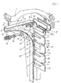
- the roller guide elements consist here of a room-side, horizontal running rail 2, which is fixed by a fastening element 7 on the garage ceiling 1, a door-side, vertical running rail 13, which is fixed in the form not shown on the front and on the floor, and one of the two running rails 13 and 2 connecting arc piece 19.
- These three guide elements can be combined as a one-piece right and, mirror image, left assembly.
- the running rails 2, 13 consist of a U-profile which is open towards the door element.
- the arc piece 19 furthermore has a deflection and locking piece 3 along the inlet-side region of the cam track 14 with a roller guide 27 running parallel and at a distance from this and an inwardly angled locking edge 28 attached to it on the door side.
- the door element or one-piece door leaf 10 shown in the drawing figures 1 to 3 is divided into sections 20 by beads 24, the beads 24 ensuring the elasticity of the door leaf and generating the required restoring force in the curve region of the curved piece 19.
- the one-piece door leaf 10 can be made of sheet metal, which is formed over the width, this door leaf 10 has recesses or beads 24 which divide into sections 20 and which give the door leaf the required elasticity and restoring force in these areas 24.
- the sections or individual gate elements 20 are each assigned rollers 4 on both sides, which are freely rotatable on bearing brackets 11 and fastened to the sections or gate elements by means of these.
- These rollers 4 roll on the inside of the inner leg 26 of the rail U-profiles, the rollers 4 being the elements supporting the gate in the horizontal region of the rails in the case of a sectional door opening to the ceiling, while in the case of the sectional door opening to the side as supporting elements the sections / gate elements 20, instead of every second or third roller 4, support rollers 31 are provided at the top, which roll on the outside of the base of the upper rail U-profiles.
- the sectional door opening to the ceiling is assigned two or more guide rollers 30 on both sides for lateral guidance of the gate, each of which is rotatably mounted on a plate 12 fastened to the gate element or the door section, the respective roller 4 also being attached to this in this guide roller position Plate 12 is rotatably mounted.
- These guide rollers 30 roll on the inside at the base of the track U-profile and thus effect the lateral guidance of the overhead sectional door.
- the door leaf 10 is formed in one piece. Parallel to each other and over the entire width of the door leaf 10 beads 24 are provided here, which on the one hand divides the door leaf 10 into more or less rigid sections 20, on the other hand the door leaf 10 over the width of the desired rigidity and perpendicular to it the required elasticity and Restoring force.
- the sections 20 of the door leaf 10 form a vertical flat surface.
- the upper roller 4a assigned to the upper section 20a at the end lies here against the locking edge 28 of the deflection and locking piece 3 directly on the inside of the cam track 14, into which it was steered in the final movement during the closing process in the direction of arrow 34 (FIG. 2) via the roller guide 27 and thus aligned the upper or last section 20a and the immediately adjacent section 20 in one plane with the other sections 20 by means of the restoring forces introduced into the door leaf by the beads 24.
- the following running rollers 4 assigned to the corresponding sections 20 are forced to roll inside the guideway 22 by the restoring forces introduced into the door leaf 10 by means of the beads 24, however, the last or end-side roller 4a before it enters the curved piece 19 inside the outer U-leg 25 of the running rail 2 by the restoring forces inevitably along the leg leading to the curved path 14 and via the roller guide 27 in the direction of the arrow 34 (FIG. 2) in the end position is directed.
- the last section 20a in the end position of the roller 4a forms a flat door surface with the other sections.
- roller 4 of this end section 20a adjacent door section 20 in the final phase of the closing movement and in the initial phase of the opening movement by the restoring forces does not roll over the entire length on the guideway 22, but rather describes a path as arrows 35 (FIG. 2) or 33 (FIG. 1) roughly represent.
- the arrangements shown in FIGS. 1 and 2 are, of course, also in mirror image design on the opposite side of the gate or the gate opening.
- a block and tackle lifting mechanism 16 with spring assembly 36 and deflection roller 37 for a pull rope 17 as weight compensation for a hand-operated gate is provided on both sides of the gate.
- the pull rope 17 can be fixed on the one hand on the lowermost section 20 of the door leaf 10, so that here in the final phase of the opening movement, contrary to the previously described direction of movement of the lower roller 4 on the inside along the outside leg of the vertical running rail 13 into the curved piece and to the curved path 14, this lower roller 4 is held on the guide track 22 by the cable 17 and the stop which stops the opening movement is provided at the end of the horizontal running rail 2 on the room side.
- the traction cable 17 can be attached to the second or third door section 20 from the front, the roller 4 of the front door section 20 reaching the end position cam track 14 by the restoring forces, as already described, and the front door section 20 to release the full usable height into the horizontal pivots.
- the upper end section 20a and the lower end section are associated with end profiles, the upper end profile 8 for sealing in the gate closed position having a brush strip 9 which is in contact with e.g. B. is arranged on the lintel 15 via a fastener 6 aperture 5 ( Figure 1 u.2).
- Both end profiles extend over the entire width of the door, the guide rollers 30 already mentioned being provided for laterally spaced guidance of the door, and a guide edge 29 angled inwards at least in the horizontal region of the inner legs 26 of the running rail 2 for safe guidance trains.
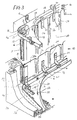
- FIG. 3 shows a rotary sectional door opening to the side in the closed position.
- Door leaf 10 with beads 24, each section 20 of the door leaf being assigned a roller 4 on both sides.
- the door leaf 10 is also guided in the running rails by means of rollers 4, while the required suspension of the door leaf takes place via support rollers 31 which, for example, are fastened to the sections 20 via a support element 38 instead of an upper roller 4.
- These support rollers 31 roll on the outside of the base of the upper U-shaped rails 2, 13 and the upper arch piece 19 during the opening and closing movement of the gate.
- An electric drive can be assigned to the overhead as well as the side sectional door, which is articulated with a push rod in the middle of the door leaf on the end profile 8 of the room-side or upper end.
- the deflection and locking piece 3 in the curved piece 19 can also be omitted, for example the push rod deflects the upper or room-side door section 20a out of the plane with the other sections 20 when the opening movement is initiated, the end-side roller 4a leads into the room-side track 2, and thus presses the following rollers 4 onto the guide track 22 and into the track 2 pulls.
Landscapes
- Engineering & Computer Science (AREA)
- Mechanical Engineering (AREA)
- Support Devices For Sliding Doors (AREA)
- Gates (AREA)
- Wing Frames And Configurations (AREA)
- Special Wing (AREA)
- Elevator Door Apparatuses (AREA)
- Securing Of Glass Panes Or The Like (AREA)
Claims (9)
- Porte à sections pour une utilisation comme porte de garage ou comme porte similaire s'ouvrant vers le plafond ou vers le côté, composée d'un certain nombre d'éléments de porte (20) fermant la baie et guidés pour l'ouverture et la fermeture par l'intermédiaire de galets de roulement (4, 4a) dans des rails de roulement (2) situés côté porte ou côté pièce, étant précisé que les rails de roulement situés côté pièce (2) prévus des deux côtés de la porte à sections sont réalisés sous la forme de rails individuels simples destinés à recevoir les galets de roulement (4, 4a) montés des deux côtés, en position ouverte de la porte à sections, sur les panneaux ou éléments de porte (20) par l'intermédiaire d'étriers de montage (11), et qu'il est prévu, pour la transition entre le rail de roulement situé côté pièce (2) et le rail de roulement situé côté porte (13), une pièce courbe (19) qui définit un angle d'environ 90 degrés et une glissière courbe extérieure (14), et est pourvue d'une pièce de déviation et d'arrêt (3) déviant, en position de porte fermée, le galet de roulement arrière (4a) associé à l'élément de porte de bordure (20a), et d'une glissière de guidage (22) déviant les autres galets de roulement (4) d'un rail de roulement à l'autre, caractérisée en ce que les panneaux ou éléments (20) formant la porte à sections sont reliés entre eux par des éléments de liaison élastiques (23) qui alignent ces éléments dans un plan et les ramènent dans ce plan, et qui ont la forme de moulures (24) longitudinales ou transversales, ces moulures (24) formant des éléments réalisés d'une seule pièce avec les éléments (20).
- Porte à sections selon la revendication 1, caractérisée en ce que les panneaux ou éléments formant cette porte sont des sections (20) d'un panneau de porte (10) fermant en une seule pièce la baie, en position fermée, qui est conçu pour faire ressort de manière élastique grâce à des moulures (24) qui le divisent en sections (20) et s'étendent sur toute la largeur.
- Porte à sections selon les revendications 1 à 2, caractérisée en ce que les rails de roulement (2, 13) sont réalisés dans un profité en U ouvert vers le panneau de porte (10), les branches intérieures (26) des profilés en U des paires respectives de rails de roulement (2, 13) disposées des deux côtés sont reliées, dans la zone de la pièce courbe (19), par la glissière de guidage (22) présentant un grand rayon et déviant les galets de roulement (4) appliqués à l'intérieur grâce à la force de rappel des moulures (24), tandis que les branches extérieures (25) des paires respectives de rails de roulement (2, 13) sont reliées, dans la zone de cette pièce courbe (19), par la glissière courbe (14) présentant un rayon sensiblement plus petit et guidant le galet de roulement (4a) appliqué à l'intérieur, et la pièce de déviation et d'arrêt (3) guidant ce galet de guidage (4a) de l'élément de porte de bordure arrière (20a) dans la position fermée et hors de cette position fermée comporte un guidage de galets de roulement (27) s'étendant du côté de l'entrée de la glissière courbe (14), parallèlement et à une certaine distance de celle-ci, ainsi qu'un bord d'arrêt (28) opposé au rayon et coudé vers l'intérieur.
- Porte à sections selon les revendications 1 à 3, caractérisée en ce que la branche intérieure (26) du rail de roulement (2) est coudée vers l'autre branche (25) sous la forme d'un bord de guidage de galets de roulement (29).
- Porte à sections selon les revendications 1 à 4, caractérisée en ce qu'il est prévu, au niveau de l'extrémité située côté pièce ou supérieure du panneau de porte (10) formé d'éléments de porte individuels ou divisé en sections (20), comme fermeture, un profilé en U (8) couvrant toute la largeur, qui est disposé, aux deux extrémités, côté frontal, pour supporter en rotation le galet de roulement (4a) roulant, suivant un guidage forcé par la pièce de déviation et d'arrêt (3), contre la glissière courbe (14) et sur la face intérieure de la branche (25), et qui comporte, en vue d'une fermeture étanche de la porte, en position fermée, une brosse d'étanchéité (9) s'étendant sur toute la largeur et dirigée vers l'extérieur.
- Porte à sections selon les revendications 1 à 5, caractérisée en ce qu'il est prévu, associée à une ou plusieurs sections ou éléments (20) de la porte, une plaque (12) recevant l'étrier de montage (11) avec le galet de roulement (4) et supportant un galet de guidage latéral (30).
- Porte à sections selon les revendications 1 à 5, caractérisée en ce qu'une ou plusieurs sections ou éléments (20) de la porte s'ouvrant vers le côté comportent des éléments de support (38) entourant les rails de roulement supérieurs (2, 13) et comportant des galets (31) montés rotatifs sur ceux-ci, au lieu de galets de roulement (4), les galets (31) roulant, en portant la porte, sur le côté extérieur de base des profilés en U des rails de roulement (2, 13).
- Porte à sections selon l'une des revendications 1 à 6, caractérisée en ce que la porte à sections s'ouvrant vers le plafond comporte des deux côtés, pour un équilibrage de poids, un mécanisme de levage à poulie multiple (16) comprenant un bloc-ressort (36) et une poulie de renvoi (37) pour un câble de traction (17) fixé à un élément de porte (20) inférieur.
- Porte à sections selon l'une des revendications 1 à 7, caractérisée en ce qu'il est prévu, associé au panneau de porte (10), un entraînement électrique à blocage automatique dont la bielle est articulée, au milieu du panneau de porte (10), au profilé de fermeture (8) situé côté extrémité ou côté pièce de telle sorte que le mouvement de fermeture et d'ouverture amenant l'élément de porte (20a) situé côté extrémité dans le plan et hors du plan des autres éléments (20) peut se faire sans bord de guidage et d'arrêt (27, 28) pour le galet de roulement (4a).
Priority Applications (5)
| Application Number | Priority Date | Filing Date | Title |
|---|---|---|---|
| EP88118600A EP0367852B1 (fr) | 1988-11-09 | 1988-11-09 | Porte à sections permettant un roulement incurvé |
| ES88118600T ES2045063T3 (es) | 1988-11-09 | 1988-11-09 | Puerta de secciones. |
| DE8888118600T DE3883242D1 (de) | 1988-11-09 | 1988-11-09 | Sektionaltor als rundlauftor. |
| AT88118600T ATE92999T1 (de) | 1988-11-09 | 1988-11-09 | Sektionaltor als rundlauftor. |
| PT90190A PT90190B (pt) | 1988-11-09 | 1989-04-04 | Porta constituida por seccoes e funcionando como porta de correr |
Applications Claiming Priority (1)
| Application Number | Priority Date | Filing Date | Title |
|---|---|---|---|
| EP88118600A EP0367852B1 (fr) | 1988-11-09 | 1988-11-09 | Porte à sections permettant un roulement incurvé |
Publications (2)
| Publication Number | Publication Date |
|---|---|
| EP0367852A1 EP0367852A1 (fr) | 1990-05-16 |
| EP0367852B1 true EP0367852B1 (fr) | 1993-08-11 |
Family
ID=8199542
Family Applications (1)
| Application Number | Title | Priority Date | Filing Date |
|---|---|---|---|
| EP88118600A Expired - Lifetime EP0367852B1 (fr) | 1988-11-09 | 1988-11-09 | Porte à sections permettant un roulement incurvé |
Country Status (5)
| Country | Link |
|---|---|
| EP (1) | EP0367852B1 (fr) |
| AT (1) | ATE92999T1 (fr) |
| DE (1) | DE3883242D1 (fr) |
| ES (1) | ES2045063T3 (fr) |
| PT (1) | PT90190B (fr) |
Cited By (1)
| Publication number | Priority date | Publication date | Assignee | Title |
|---|---|---|---|---|
| DE202006017312U1 (de) * | 2006-11-10 | 2008-03-13 | Rehau Ag + Co | Verschlussanordnung |
Families Citing this family (9)
| Publication number | Priority date | Publication date | Assignee | Title |
|---|---|---|---|---|
| DE4031388C2 (de) * | 1990-10-04 | 1993-10-21 | Erich Doering | Seitensektionaltor oder Rundlauftor, Deckensektionaltor |
| US5425409A (en) * | 1993-12-17 | 1995-06-20 | Guia; Armando E. | Door mounting system |
| DE19637919C2 (de) * | 1996-09-17 | 2000-05-31 | Doering Normstahl Werk | Decken- oder Seitenlauf-Sektionaltor |
| WO1998030776A1 (fr) * | 1997-01-10 | 1998-07-16 | Hörmann KG Brockhagen | Porte articulee au plafond pour hauteurs de chute particulierement faibles |
| AT503260B1 (de) * | 2006-02-16 | 2008-06-15 | Mewald Franz Ing | Sektionaltor |
| IT201700104198A1 (it) * | 2017-09-18 | 2019-03-18 | Flavio Martinelli | Porta sezionale a scorrimento laterale su monoguida |
| USD896616S1 (en) | 2018-03-22 | 2020-09-22 | Clopay Building Products Company, Inc. | Garage door cam |
| US11105133B2 (en) | 2018-04-17 | 2021-08-31 | Clopay Building Products Company, Inc. | High-speed sectional door |
| CN113064104A (zh) * | 2021-03-17 | 2021-07-02 | 安徽莱特实业集团有限公司 | 一种全自动变比及直流电阻测试装置 |
Family Cites Families (3)
| Publication number | Priority date | Publication date | Assignee | Title |
|---|---|---|---|---|
| US2573962A (en) * | 1949-05-25 | 1951-11-06 | Earl C Fox | Sectional door |
| CH343624A (de) * | 1955-03-09 | 1959-12-31 | Morrison Steel Products Inc | In Führungsschienen laufende Gliedertür |
| DE8703826U1 (de) * | 1987-03-13 | 1987-04-30 | Max Meir "Rundum"-Garagentore und Wetterschutz, 8898 Schrobenhausen | Schiebetor |
-
1988
- 1988-11-09 ES ES88118600T patent/ES2045063T3/es not_active Expired - Lifetime
- 1988-11-09 DE DE8888118600T patent/DE3883242D1/de not_active Expired - Lifetime
- 1988-11-09 AT AT88118600T patent/ATE92999T1/de not_active IP Right Cessation
- 1988-11-09 EP EP88118600A patent/EP0367852B1/fr not_active Expired - Lifetime
-
1989
- 1989-04-04 PT PT90190A patent/PT90190B/pt not_active IP Right Cessation
Cited By (1)
| Publication number | Priority date | Publication date | Assignee | Title |
|---|---|---|---|---|
| DE202006017312U1 (de) * | 2006-11-10 | 2008-03-13 | Rehau Ag + Co | Verschlussanordnung |
Also Published As
| Publication number | Publication date |
|---|---|
| ES2045063T3 (es) | 1994-01-16 |
| EP0367852A1 (fr) | 1990-05-16 |
| ATE92999T1 (de) | 1993-08-15 |
| PT90190A (pt) | 1990-05-31 |
| DE3883242D1 (de) | 1993-09-16 |
| PT90190B (pt) | 1995-05-31 |
Similar Documents
| Publication | Publication Date | Title |
|---|---|---|
| EP0367852B1 (fr) | Porte à sections permettant un roulement incurvé | |
| EP0890011A1 (fr) | Porte tournante | |
| EP1498382B1 (fr) | Linteau for porte d'ascenseur | |
| EP1092074A1 (fr) | Porte articulee au plafond pour hauteurs de chute particulierement faibles | |
| DE10329798B4 (de) | Sektionaltor | |
| EP0556632B1 (fr) | Porte roulante horizontale | |
| DE1559958B1 (de) | Freitragendes Schiebetor | |
| EP0468223A2 (fr) | Porte accordéon | |
| EP0905343B1 (fr) | Agencement de fenêtre ou de porte | |
| DE19518499A1 (de) | Schiebetüranordnung | |
| AT397122B (de) | Garagenschwingtor mit nicht ausschwenkendem torblatt | |
| DE19719011C2 (de) | Führungsschiene für ein Laufwerk mit am Laufwerk hängend gelagerten Trennwänden oder dergleichen | |
| EP1034999B1 (fr) | Wagon de marchandises avec paroi coulissante | |
| DE69826056T2 (de) | Gewichtsausgleich- und Führungseinrichtung für Schiebetüren | |
| DE2451735A1 (de) | Antriebs- und aufhaengevorrichtung fuer doppelschwenkschiebetueren | |
| DE202007014472U9 (de) | Türkonstruktion für einen Aufzug | |
| DE8913893U1 (de) | Schließvorrichtung für Türen, Tore, Fenster, Klappen o.dgl. | |
| CH688593A5 (de) | Faltbare Vorrichtung zum Verschliessen von Gebaeude oeffnungen, insbesondere fuer ein Faltdach oder Falttor. | |
| DE2220433B2 (de) | Arretiervorrichtung für Roll- oder Faltladen zwecks Vermeidens von Geräuschentwicklung bei Wind, Erschütterungen od.dgl | |
| DE19501045C2 (de) | Führungsrolle zur Befestigung am unteren Rand eines Schiebetores oder dergl., insbesondere für eine Garage | |
| DE20300786U1 (de) | Seitenlauftor | |
| DE19519905C2 (de) | Tür für Fahrkörbe von Aufzügen | |
| DE4030197A1 (de) | Rolltor | |
| DE19731932A1 (de) | Deckengliedertor für besonders niedrige Sturzhöhen | |
| DE2846326C2 (fr) |
Legal Events
| Date | Code | Title | Description |
|---|---|---|---|
| PUAI | Public reference made under article 153(3) epc to a published international application that has entered the european phase |
Free format text: ORIGINAL CODE: 0009012 |
|
| AK | Designated contracting states |
Kind code of ref document: A1 Designated state(s): AT CH DE ES FR GR IT LI |
|
| 17P | Request for examination filed |
Effective date: 19900619 |
|
| 17Q | First examination report despatched |
Effective date: 19920123 |
|
| GRAA | (expected) grant |
Free format text: ORIGINAL CODE: 0009210 |
|
| AK | Designated contracting states |
Kind code of ref document: B1 Designated state(s): AT CH DE ES FR GR IT LI |
|
| REF | Corresponds to: |
Ref document number: 92999 Country of ref document: AT Date of ref document: 19930815 Kind code of ref document: T |
|
| REF | Corresponds to: |
Ref document number: 3883242 Country of ref document: DE Date of ref document: 19930916 |
|
| ITF | It: translation for a ep patent filed | ||
| ET | Fr: translation filed | ||
| REG | Reference to a national code |
Ref country code: ES Ref legal event code: FG2A Ref document number: 2045063 Country of ref document: ES Kind code of ref document: T3 |
|
| REG | Reference to a national code |
Ref country code: GR Ref legal event code: FG4A Free format text: 3010343 |
|
| PLBE | No opposition filed within time limit |
Free format text: ORIGINAL CODE: 0009261 |
|
| STAA | Information on the status of an ep patent application or granted ep patent |
Free format text: STATUS: NO OPPOSITION FILED WITHIN TIME LIMIT |
|
| 26N | No opposition filed | ||
| REG | Reference to a national code |
Ref country code: CH Ref legal event code: NV Representative=s name: SCHMAUDER & WANN PATENTANWALTSBUERO, INHABER KLAUS Ref country code: CH Ref legal event code: PUE Owner name: DR. H.C. ERICH DOERING TRANSFER- NORMSTAHL E. DOER |
|
| REG | Reference to a national code |
Ref country code: FR Ref legal event code: TP |
|
| REG | Reference to a national code |
Ref country code: ES Ref legal event code: PC2A |
|
| REG | Reference to a national code |
Ref country code: FR Ref legal event code: TP |
|
| REG | Reference to a national code |
Ref country code: CH Ref legal event code: PUE Owner name: NORMSTAHL E. DOERING AG TRANSFER- NORMSTAHL WERK E |
|
| REG | Reference to a national code |
Ref country code: ES Ref legal event code: PC2A |
|
| PGFP | Annual fee paid to national office [announced via postgrant information from national office to epo] |
Ref country code: DE Payment date: 20071126 Year of fee payment: 20 Ref country code: ES Payment date: 20071127 Year of fee payment: 20 |
|
| PGFP | Annual fee paid to national office [announced via postgrant information from national office to epo] |
Ref country code: AT Payment date: 20071017 Year of fee payment: 20 Ref country code: IT Payment date: 20071127 Year of fee payment: 20 Ref country code: CH Payment date: 20071019 Year of fee payment: 20 |
|
| PGFP | Annual fee paid to national office [announced via postgrant information from national office to epo] |
Ref country code: FR Payment date: 20071017 Year of fee payment: 20 |
|
| PGFP | Annual fee paid to national office [announced via postgrant information from national office to epo] |
Ref country code: GR Payment date: 20071129 Year of fee payment: 20 |
|
| REG | Reference to a national code |
Ref country code: CH Ref legal event code: PL |
|
| REG | Reference to a national code |
Ref country code: ES Ref legal event code: FD2A Effective date: 20081110 |
|
| PG25 | Lapsed in a contracting state [announced via postgrant information from national office to epo] |
Ref country code: ES Free format text: LAPSE BECAUSE OF EXPIRATION OF PROTECTION Effective date: 20081110 |