EP0367854A1 - Passivation de catalyseurs de craquage contaminés par des métaux - Google Patents
Passivation de catalyseurs de craquage contaminés par des métaux Download PDFInfo
- Publication number
- EP0367854A1 EP0367854A1 EP88118654A EP88118654A EP0367854A1 EP 0367854 A1 EP0367854 A1 EP 0367854A1 EP 88118654 A EP88118654 A EP 88118654A EP 88118654 A EP88118654 A EP 88118654A EP 0367854 A1 EP0367854 A1 EP 0367854A1
- Authority
- EP
- European Patent Office
- Prior art keywords
- end portion
- passivating agent
- recited
- agent
- catalytic cracking
- Prior art date
- Legal status (The legal status is an assumption and is not a legal conclusion. Google has not performed a legal analysis and makes no representation as to the accuracy of the status listed.)
- Granted
Links
- 229910052751 metal Inorganic materials 0.000 title claims abstract description 92
- 239000002184 metal Substances 0.000 title claims abstract description 92
- 239000003054 catalyst Substances 0.000 title claims description 74
- 238000005336 cracking Methods 0.000 title claims description 60
- 238000002161 passivation Methods 0.000 title description 8
- 239000003795 chemical substances by application Substances 0.000 claims abstract description 155
- 150000002739 metals Chemical class 0.000 claims abstract description 85
- 238000004523 catalytic cracking Methods 0.000 claims abstract description 72
- 238000002347 injection Methods 0.000 claims abstract description 61
- 239000007924 injection Substances 0.000 claims abstract description 61
- 239000002270 dispersing agent Substances 0.000 claims abstract description 54
- 238000000034 method Methods 0.000 claims abstract description 47
- 230000008569 process Effects 0.000 claims abstract description 35
- 238000007599 discharging Methods 0.000 claims abstract description 21
- 238000002844 melting Methods 0.000 claims abstract description 7
- 230000008018 melting Effects 0.000 claims abstract description 7
- 206010037660 Pyrexia Diseases 0.000 claims abstract 2
- 229930195733 hydrocarbon Natural products 0.000 claims description 44
- 150000002430 hydrocarbons Chemical class 0.000 claims description 44
- 239000004215 Carbon black (E152) Substances 0.000 claims description 39
- 238000011144 upstream manufacturing Methods 0.000 claims description 34
- 230000008929 regeneration Effects 0.000 claims description 26
- 238000011069 regeneration method Methods 0.000 claims description 26
- ADCOVFLJGNWWNZ-UHFFFAOYSA-N antimony trioxide Chemical compound O=[Sb]O[Sb]=O ADCOVFLJGNWWNZ-UHFFFAOYSA-N 0.000 claims description 20
- 229910052787 antimony Inorganic materials 0.000 claims description 13
- WATWJIUSRGPENY-UHFFFAOYSA-N antimony atom Chemical compound [Sb] WATWJIUSRGPENY-UHFFFAOYSA-N 0.000 claims description 13
- 239000007900 aqueous suspension Substances 0.000 claims description 7
- 239000003921 oil Substances 0.000 claims description 7
- LJCFOYOSGPHIOO-UHFFFAOYSA-N antimony pentoxide Chemical compound O=[Sb](=O)O[Sb](=O)=O LJCFOYOSGPHIOO-UHFFFAOYSA-N 0.000 claims description 6
- 230000006872 improvement Effects 0.000 claims description 6
- 239000007787 solid Substances 0.000 claims description 3
- DHZCVEDTDMGIHQ-UHFFFAOYSA-N 1-(1-hydroxyethylsulfanyl)ethanol Chemical compound CC(O)SC(C)O DHZCVEDTDMGIHQ-UHFFFAOYSA-N 0.000 claims description 2
- 239000007983 Tris buffer Substances 0.000 claims description 2
- 239000011261 inert gas Substances 0.000 claims description 2
- XLYOFNOQVPJJNP-UHFFFAOYSA-N water Substances O XLYOFNOQVPJJNP-UHFFFAOYSA-N 0.000 claims description 2
- 239000003570 air Substances 0.000 claims 1
- 229910000410 antimony oxide Inorganic materials 0.000 claims 1
- VTRUBDSFZJNXHI-UHFFFAOYSA-N oxoantimony Chemical class [Sb]=O VTRUBDSFZJNXHI-UHFFFAOYSA-N 0.000 claims 1
- 230000008901 benefit Effects 0.000 description 6
- 238000005259 measurement Methods 0.000 description 6
- 239000000571 coke Substances 0.000 description 5
- 230000000694 effects Effects 0.000 description 5
- 239000000203 mixture Substances 0.000 description 5
- XEEYBQQBJWHFJM-UHFFFAOYSA-N Iron Chemical compound [Fe] XEEYBQQBJWHFJM-UHFFFAOYSA-N 0.000 description 4
- PXHVJJICTQNCMI-UHFFFAOYSA-N Nickel Chemical compound [Ni] PXHVJJICTQNCMI-UHFFFAOYSA-N 0.000 description 4
- 230000002411 adverse Effects 0.000 description 4
- 230000003247 decreasing effect Effects 0.000 description 4
- UFHFLCQGNIYNRP-UHFFFAOYSA-N Hydrogen Chemical compound [H][H] UFHFLCQGNIYNRP-UHFFFAOYSA-N 0.000 description 3
- 238000006243 chemical reaction Methods 0.000 description 3
- 239000010779 crude oil Substances 0.000 description 3
- 239000001257 hydrogen Substances 0.000 description 3
- 229910052739 hydrogen Inorganic materials 0.000 description 3
- 238000012986 modification Methods 0.000 description 3
- 230000004048 modification Effects 0.000 description 3
- RYGMFSIKBFXOCR-UHFFFAOYSA-N Copper Chemical compound [Cu] RYGMFSIKBFXOCR-UHFFFAOYSA-N 0.000 description 2
- 230000003466 anti-cipated effect Effects 0.000 description 2
- 230000015572 biosynthetic process Effects 0.000 description 2
- 229910017052 cobalt Inorganic materials 0.000 description 2
- 239000010941 cobalt Substances 0.000 description 2
- GUTLYIVDDKVIGB-UHFFFAOYSA-N cobalt atom Chemical compound [Co] GUTLYIVDDKVIGB-UHFFFAOYSA-N 0.000 description 2
- 239000000356 contaminant Substances 0.000 description 2
- 238000007796 conventional method Methods 0.000 description 2
- 229910052802 copper Inorganic materials 0.000 description 2
- 239000010949 copper Substances 0.000 description 2
- 239000006185 dispersion Substances 0.000 description 2
- 238000005755 formation reaction Methods 0.000 description 2
- 238000010348 incorporation Methods 0.000 description 2
- 229910052742 iron Inorganic materials 0.000 description 2
- 239000007788 liquid Substances 0.000 description 2
- 239000007791 liquid phase Substances 0.000 description 2
- 238000004519 manufacturing process Methods 0.000 description 2
- 229910052759 nickel Inorganic materials 0.000 description 2
- BASFCYQUMIYNBI-UHFFFAOYSA-N platinum Chemical compound [Pt] BASFCYQUMIYNBI-UHFFFAOYSA-N 0.000 description 2
- 229910052720 vanadium Inorganic materials 0.000 description 2
- GPPXJZIENCGNKB-UHFFFAOYSA-N vanadium Chemical compound [V]#[V] GPPXJZIENCGNKB-UHFFFAOYSA-N 0.000 description 2
- AHBGXHAWSHTPOM-UHFFFAOYSA-N 1,3,2$l^{4},4$l^{4}-dioxadistibetane 2,4-dioxide Chemical compound O=[Sb]O[Sb](=O)=O AHBGXHAWSHTPOM-UHFFFAOYSA-N 0.000 description 1
- VYZAMTAEIAYCRO-UHFFFAOYSA-N Chromium Chemical compound [Cr] VYZAMTAEIAYCRO-UHFFFAOYSA-N 0.000 description 1
- 230000009471 action Effects 0.000 description 1
- 238000005273 aeration Methods 0.000 description 1
- 229910000411 antimony tetroxide Inorganic materials 0.000 description 1
- 230000003197 catalytic effect Effects 0.000 description 1
- 229910052804 chromium Inorganic materials 0.000 description 1
- 239000011651 chromium Substances 0.000 description 1
- 238000002485 combustion reaction Methods 0.000 description 1
- 238000004891 communication Methods 0.000 description 1
- 150000001875 compounds Chemical class 0.000 description 1
- 230000007423 decrease Effects 0.000 description 1
- 238000013461 design Methods 0.000 description 1
- 230000001627 detrimental effect Effects 0.000 description 1
- 239000012530 fluid Substances 0.000 description 1
- 238000004231 fluid catalytic cracking Methods 0.000 description 1
- 239000002803 fossil fuel Substances 0.000 description 1
- 239000000295 fuel oil Substances 0.000 description 1
- 239000007789 gas Substances 0.000 description 1
- 239000003502 gasoline Substances 0.000 description 1
- 230000007257 malfunction Effects 0.000 description 1
- 239000000463 material Substances 0.000 description 1
- 230000000116 mitigating effect Effects 0.000 description 1
- 239000003208 petroleum Substances 0.000 description 1
- 239000003209 petroleum derivative Substances 0.000 description 1
- 230000000704 physical effect Effects 0.000 description 1
- 229910052697 platinum Inorganic materials 0.000 description 1
- 230000002035 prolonged effect Effects 0.000 description 1
- 230000001737 promoting effect Effects 0.000 description 1
- 230000000630 rising effect Effects 0.000 description 1
- 239000007790 solid phase Substances 0.000 description 1
- 239000000126 substance Substances 0.000 description 1
Images

Classifications
-
- B—PERFORMING OPERATIONS; TRANSPORTING
- B01—PHYSICAL OR CHEMICAL PROCESSES OR APPARATUS IN GENERAL
- B01J—CHEMICAL OR PHYSICAL PROCESSES, e.g. CATALYSIS OR COLLOID CHEMISTRY; THEIR RELEVANT APPARATUS
- B01J19/00—Chemical, physical or physico-chemical processes in general; Their relevant apparatus
- B01J19/26—Nozzle-type reactors, i.e. the distribution of the initial reactants within the reactor is effected by their introduction or injection through nozzles
-
- C—CHEMISTRY; METALLURGY
- C10—PETROLEUM, GAS OR COKE INDUSTRIES; TECHNICAL GASES CONTAINING CARBON MONOXIDE; FUELS; LUBRICANTS; PEAT
- C10G—CRACKING HYDROCARBON OILS; PRODUCTION OF LIQUID HYDROCARBON MIXTURES, e.g. BY DESTRUCTIVE HYDROGENATION, OLIGOMERISATION, POLYMERISATION; RECOVERY OF HYDROCARBON OILS FROM OIL-SHALE, OIL-SAND, OR GASES; REFINING MIXTURES MAINLY CONSISTING OF HYDROCARBONS; REFORMING OF NAPHTHA; MINERAL WAXES
- C10G11/00—Catalytic cracking, in the absence of hydrogen, of hydrocarbon oils
- C10G11/14—Catalytic cracking, in the absence of hydrogen, of hydrocarbon oils with preheated moving solid catalysts
- C10G11/18—Catalytic cracking, in the absence of hydrogen, of hydrocarbon oils with preheated moving solid catalysts according to the "fluidised-bed" technique
-
- B—PERFORMING OPERATIONS; TRANSPORTING
- B01—PHYSICAL OR CHEMICAL PROCESSES OR APPARATUS IN GENERAL
- B01J—CHEMICAL OR PHYSICAL PROCESSES, e.g. CATALYSIS OR COLLOID CHEMISTRY; THEIR RELEVANT APPARATUS
- B01J2219/00—Chemical, physical or physico-chemical processes in general; Their relevant apparatus
- B01J2219/00049—Controlling or regulating processes
- B01J2219/00051—Controlling the temperature
-
- B—PERFORMING OPERATIONS; TRANSPORTING
- B01—PHYSICAL OR CHEMICAL PROCESSES OR APPARATUS IN GENERAL
- B01J—CHEMICAL OR PHYSICAL PROCESSES, e.g. CATALYSIS OR COLLOID CHEMISTRY; THEIR RELEVANT APPARATUS
- B01J2219/00—Chemical, physical or physico-chemical processes in general; Their relevant apparatus
- B01J2219/00049—Controlling or regulating processes
- B01J2219/00162—Controlling or regulating processes controlling the pressure
-
- C—CHEMISTRY; METALLURGY
- C10—PETROLEUM, GAS OR COKE INDUSTRIES; TECHNICAL GASES CONTAINING CARBON MONOXIDE; FUELS; LUBRICANTS; PEAT
- C10G—CRACKING HYDROCARBON OILS; PRODUCTION OF LIQUID HYDROCARBON MIXTURES, e.g. BY DESTRUCTIVE HYDROGENATION, OLIGOMERISATION, POLYMERISATION; RECOVERY OF HYDROCARBON OILS FROM OIL-SHALE, OIL-SAND, OR GASES; REFINING MIXTURES MAINLY CONSISTING OF HYDROCARBONS; REFORMING OF NAPHTHA; MINERAL WAXES
- C10G2300/00—Aspects relating to hydrocarbon processing covered by groups C10G1/00 - C10G99/00
- C10G2300/70—Catalyst aspects
- C10G2300/705—Passivation
Definitions
- the present invention relates to the art of catalytic cracking of hydrocarbons. Particularly, the invention relates to the restoration of cracking catalysts which have contacted a hydrocarbon feedstock. More particularly, the invention relates to the passivation of contaminating metals, deposited onto cracking catalysts which have contacted a hydrocarbon feedstock, through the utilization of passivating agents.
- Fossil fuels are one of the world's leading sources of energy.
- known oil reserves are finite; therefore, there exists a need to improve the process for converting crude oil into usable petroleum products.
- hydrocarbon feedstocks containing higher molecular weight hydrocarbons have their molecular weight reduced (i.e. "cracked") by being contacted under elevated temperatures with a cracking catalyst thereby producing light distillates such as gasoline.
- metals such as nickel, vanadium, iron, copper and/or cobalt, present in the feedstocks, become deposited on the cracking catalyst promoting excessive hydrogen and coke formations. Since the production of hydrogen and coke generally has an adverse effect on the production of usable products, these are undesirable products of a cracking process. Although the cracking catalyst does undergo a regeneration process, the metal contaminants, which cause the excessive formation of hydrogen and coke, are not removed by a catalyst regeneration operation. Therefore, there exists a need to mitigate the adverse effects of contaminating metals on cracking catalysts.
- passivation is defined as a method for decreasing the detrimental catalytic effects of metal contaminants such as nickel, vanadium, iron, copper and/or cobalt which become deposited on the cracking catalyst during a catalytic cracking process. Therefore, by passivating the contaminating metal deposits on cracking catalysts, the catalysts' life and desired product yields can be prolonged and increased respectively.
- metals passivating agents are dispersed into the hydrocarbon cracking zone of a catalytic cracking unit which includes the hydrocarbon cracking reactor and the hydrocarbon feedstream conduit.
- the conventional method of dispersing these metals passivating agents into the hydrocarbon cracking zone has been to either use a tubular conduit which opens into the sidewall of the catalytic cracking unit or to use a quill which extends through the sidewall of a catalytic cracking unit and into the desired point of dispersion.
- metals passivating agent In comparison to the amount of cracking catalyst and hydrocarbon feedstock flowing through a catalytic cracking unit, a relatively small amount of metals passivating agent is required in conventional catalytic cracking processes. In order to avoid problems, such as the backflowing of catalyst and/or hydrocarbons into the passivating injection means, this small amount of metals passivating agent must be injected at a relatively high velocity. Consequently, the inside diameter of the passage through which metals passivating agents have been conventionally injected into the hydrocarbon cracking zone are generally relatively small (i.e. ranging from about 1/8 inch to about 1/2 inch).
- a "high-temperature zone" of a catalyst cracking system refers to any zone of the system wherein the temperature range of that zone exceeds the melting point of the particular passivating agent injected therein. The reason such a limitation exists is based on the physical conditions observed at the high-temperature zone and the physical characteristics of the selected metals passivating agent and/or dispersing agent.
- the agent will begin to melt at, or before, the point of injection and solidify within the cooler portion of the passivating agent injection means; thus inevitably clogging the small-diametered injection means through which the agent is injected. It may be assumed that this clogging problem can be overcome by increasing the velocity of the metals passivating agent as it is injected into the particular high-temperature zone. This assumption is erroneous, however, since, as mentioned earlier, the amount of metals passivating agent used for a particular conventional catalytic cracking system is generally constant and relatively small.
- one object of this invention is to provide a novel nozzle for discharging a relatively small amount of a metals passivating agent into a catalytic cracking unit at a relatively high velocity through a relatively large diameter opening.
- Another object of this invention is to provide, for a catalytic cracking system utilizing metals passivating agents, an improvement comprising a means for efficiently discharging a relatively small amount of a metals passivating agent into a high-temperature zone of a catalytic cracking unit.
- this invention provides, among other things, a novel nozzle for discharging a relatively small amount of a metals passivating agent into a catalytic cracking unit at a relatively high velocity through a relatively large diameter opening. Furthermore, this invention also provides a novel process for efficiently discharging a relatively small amount of a metals passivating agent into a high-temperature zone of a catalytic cracking unit, wherein the temperature range of the high-temperature zone exceeds the melting point of the particular passivating agent, through the utilization of a novel metals passivating agent injection nozzle which disperses the passivating agent, prior to discharging the agent into a catalytic cracking system, and accelerates this dispersed metals passivating agent to a maximum discharge velocity by injecting a dispersing agent into the novel nozzle at a location behind that at which the passivating agent is injected, and then discharging the dispersed metals passivating agent at a relatively high velocity through a passage having a relatively large inside
- the term "cracking catalyst ⁇ refers to any catalytic cracking material which may be suitable for cracking hydrocarbons.
- any suitable cracking catalyst may be utilized.
- the cracking catalyst can contain a combustion promoter such as platinum or chromium.
- a "used (contaminated) cracking catalyst” refers to any cracking catalyst which has contacted a hydrocarbon feedstock and, thus, contains contaminating metals therein or thereon.
- a "metals passivation (process)" as used herein refers to a procedure conducted in a catalytic cracking unit wherein adverse effects, caused by contaminating metal deposits from the feedstock being deposited onto the cracking catalyst, are precluded or mitigated by the utilization of a metals passivating agent.
- Conventional methods of metals passivation have been either to use a small diameter pipe or quill and discharge the passivating agents into the hydrocarbon feedstream or the hydrocarbon cracking reactor.
- a "(metals) passivating agent” refers to any suitable composition which has the ability to passivate contaminating metals in or on cracking catalysts without substantially hindering the cracking activity of the catalyst.
- metals passivating agents comprise antimony, due in part to its proven effectiveness and commercial availability.
- antimony refers to any suitable antimony source which is either itself an oxide or is convertible to an oxide.
- suitable antimony sources include, but are not limited to, antimony trioxide, antimony tetroxide, antimony pentoxide and the like. Mixtures of any two or more suitable antimony sources can be employed.
- These antimony-containing metals passivating agents can be dispersed into a catalytic cracking unit while either in a solid or a liquid phase.
- catalytic cracking unit refers to any hydrocarbon cracking unit wherein contaminating metals, deposited in or on the cracking catalyst, are passivated by discharging any metals passivating agent into or onto the contaminated catalyst.
- suitable catalytic cracking units include, but are not limited to, Thermofor Catalytic Cracking Units (TCCU), Heavy Oil Cracking units (H0C) and Fluid Catalytic Cracking Units (FCCU).
- TCCU Thermofor Catalytic Cracking Units
- H0C Heavy Oil Cracking units
- FCCU Fluid Catalytic Cracking Units
- all of the aforementioned cracking units comprise a hydrocarbon cracking reaction zone and a catalyst regeneration zone.
- hydrocarbon cracking zone refers to that portion of a hydrocarbon cracking unit pertaining to the catalytic cracking of high molecular weight feedstocks.
- the hydrocarbon cracking zone includes all points between that at which the hydrocarbon feedstock enters the catalytic cracking unit and that at which the used cracking catalyst exits the hydrocarbon cracking reactor.
- catalyst regeneration zone refers to that portion of a hydrocarbon cracking unit pertaining to the regeneration of cracking catalysts.
- the catalyst regeneration zone includes all points between that at which the used cracking catalyst exits the hydrocarbon cracking reactor and that at which the hydrocarbon feedstock enters the catalytic cracking unit.
- hydrocarbon Cracking Zone Temperature 800° - 1200°F, 427° - 649°C.).
- Pressure Atmospheric to 50 p.s.i.a. 1
- Catalyst Regeneration Zone Temperature 1000° - 1500°F, (538° - 816°C.). Time: 2 - 40 minutes.
- Pressure Atmospheric to 50 p.s.i.a. Air at 60°F.(16°C.) and at 1 atmosphere: 100 - 250 ft3/lb coke, (6.2 - 15.6 m3/kg coke). 1
- the abbreviation p.s.i.a. refers to a standard measurement of pressure (i.e. pounds per square inch absolute)
- this invention provides an improved method of discharging any suitable metals passivating agent into either the hydrocarbon cracking zone or the catalyst regeneration zone of a catalytic cracking unit.
- the improvement comprises the use of a novel passivating agent injection nozzle which accelerates a passivating agent to a maximum velocity by dispersing the passivating agent, through the injection of a dispersing agent into the novel nozzle at a location behind that at which the passivating agent is injected and discharges the dispersed passivating agent into a suitable location of a catalytic cracking system. Consequently, this novel nozzle discharges a dispersed passivating agent through a passage having a relatively large inside diameter after accelerating it to a maximum discharge velocity.
- the use of this novel metals passivating agent injection nozzle has inherent advantages over conventional injection methods. One such advantage is that the novel injection nozzle described herein can efficiently discharge metals passivating agents into a high-temperature zone of a catalytic cracking system.
- the passivating agent injection nozzle (hereinafter referred to as injection nozzle) of this invention, having an upstream end portion and a downstream end portion, wherein the downstream end opens into a sidewall of a catalytic cracking unit, comprises four major zones.
- the injection nozzle comprises a dispersing agent inlet zone wherein any suitable dispersing agent is injected into the upstream end portion of the defined cavity within the body of the novel injection nozzle.
- the nozzle also comprises a passivating agent inlet zone, wherein any suitable passivating agent is injected into the defined cavity within the body of the injection nozzle at a point, however, which is downstream of the dispersing agent inlet zone.
- discharge velocity refers to the velocity of a particular medium while flowing along the same longitudinal axis as the nozzle discharge end opening into a catalytic cracking unit.
- the injection nozzle further comprises a passivating agent dispersion zone wherein the selected dispersing agent disperses and accelerates the selected passivating agent to a maximum discharge velocity by combining with the passivating agent after the dispersing agent has achieved its maximum discharge velocity.
- the nozzle comprises a discharging zone wherein the dispersed passivating agent, which has been accelerated to a maximum discharge velocity, is discharged into any suitable location of a catalytic cracking system.
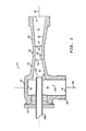
- Injection nozzle 10 includes a shell member 20 having an inside wall surface 30 which defines a cavity and various passages (i.e. chambers) therein which are hereinafter described.
- Shell member 20 includes sections 22, 24, 26 and 28.
- one end of section 22 is partially closed off by means of screw flange 18.
- the inside wall surface 30 of shell member 20 and screw flange 18 define within section 22 a generally cylindrical chamber 40 having an upstream end 42 and a downstream end 44.
- the inside wall surface 30 of shell member 20 defines within section 24 a generally frustoconical chamber 50 having an upstream end 52 and a downstream end 54.
- the upstream end 52 of frustoconical chamber 50 has a larger inside diameter measurement than the downstream end 54 of frustoconical chamber 50.
- the inside wall surface 30 of shell member 20 defines within section 26 a generally cylindrical chamber 60 having an upstream end 62 and a downstream end 64.
- the upstream end 62 of cylindrical chamber 60 has the same inside diameter measurement as the downstream end 54 of frustoconical chamber 50.
- the inside wall surface 30 of shell member 20 defines within section 28 a generally frustoconical chamber 70 having an upstream end 72 and a downstream end 74.
- the upstream end 72 of frustoconical chamber 70 has the same inside diameter measurement as the downstream end 64 of cylindrical chamber 60.
- the downstream end 74 of frustoconical chamber 70 has a larger inside diameter measurement than the upstream end 72 of frustoconical chamber 70.
- Chambers 50, 60 and 70 of shell member 20 all lie on longitudinal axis 80.
- Chamber 40 of shell member 20 lies on longitudinal axis 90.
- Longitudinal axis 80 is generally perpendicular to longitudinal axis 90.
- the chambers 40, 50, 60 and 70 of sections 22, 24, 26 and 28, respectively, are interconnected to one another as follows.
- the downstream end 44 of cylindrical chamber 40 opens into the upstream end 52 of frustoconical chamber 50.
- Frustoconical chamber 50 converges from its upstream end 52 to its downstream end 54 which opens into the upstream end 62 of cylindrical chamber 60.
- the downstream end 64 of cylindrical chamber 60 opens into the upstream end 72 of frustoconical chamber 70 which diverges to its downstream end 74.
- a metals passivating agent inlet conduit 100 extends through screw flange 18, through chamber 40 of section 26 and opens into the frustoconical chamber 50 of section 24. As shown in FIGURE 1, passivating agent inlet conduit 100 is generally aligned on longitudinal axis 80 and opens beyond the upstream end 52 of frustoconical chamber 50. As explained earlier, it is critical, when practicing the embodiments of this invention, to have the passivating agent inlet conduit open downstream from the upstream end 52 of chamber 50.
- the novel injection nozzle 10 illustrated in FIGURE 1 discharges a metals passivating agent as follows.
- the dispersing agent is injected into the dispersing agent inlet zone 120, located within chamber 40 of section 22.
- the selected dispersing agent can be injected into inlet zone 120 under any suitable pressure.
- the dispersing agent is injected under a pressure ranging from about 30 p.s.i.a. to about 150 p.s.i.a.
- Chamber 40 may have any suitable configuration.
- chamber 40 is cylindrical and has an inside diameter ranging from about 1/2 inch to about 11 ⁇ 2 inches.
- the dispersing agent is at its maximum discharge velocity as it enters the upstream end 52 of chamber 50 since that is the point at which the entire flow of the dispersing agent is concentrated along the same longitudinal axis as the discharge end portion opening of the novel injection nozzle.
- the passivating agent is injected into the passivating agent inlet zone 110 through passivating agent inlet conduit 100 which opens beyond the upstream end 52 of chamber 50 of section 24 and downstream of the dispersing agent inlet zone 120.
- the selected passivating agent may be injected into chamber 50 under any suitable pressure.
- a suitable metals passivating agent may not require the need of any injection pressure. For example, the rapid movement of the dispersing agent through chambers 50, 60 and 70 results in a lowering of the ambient pressure within these chambers; thus drawing, by means of sucking action, the selected metals passivating agent through conduit 100 into the passivating agent inlet zone 110.
- the metals passivating agent is injected under a pressure ranging from about 20 p.s.i.a. to about 100 p.s.i.a.
- Passivating agent inlet conduit 100 may have any suitable configuration.
- conduit 100 is cylindrical and has an inside diameter ranging from about 1/8 inch to about 1/2 inch.
- the dispersing agent inlet zone 120 is upstream from the passivating agent inlet zone 110.
- the dispersing agent in order to accelerate the dispersed passivating agent to a maximum discharge velocity, the dispersing agent must contact the passivating agent after the dispersing agent has achieved its maximum discharge velocity. Therefore, the relative injection location of the dispersing and passivating agents disclosed herein is a critical feature when practicing the embodiments of this invention.
- the dispersing agent After the dispersing agent has achieved its maximum discharge velocity, it combines with the passivating agent, which achieves its maximum discharge velocity as it exits the passivating agent inlet conduit, within chambers 50, 60 and 70 of sections 24, 26 and 28 respectively, to form a dispersed passivating agent mixture. As this dispersed passivating mixture travels through chambers 50, 60 and 70, its velocity is accelerated. When the dispersed passivating mixture is discharged from injection nozzle 10 through the downstream end 74 of chamber 70 it is traveling at its maximum discharge velocity.
- the downstream end 74 of chamber 70 may have any suitable inside diameter measurement. Preferably, the inside diameter of the downstream end 74 of chamber 70 ranges from about 3/4 inch to about 21 ⁇ 2 inches.
- Chambers 50, 60 and 70 of sections 24, 26 and 28, respectively, may have any suitable configuration.
- suitable chamber configurations include, but are not limited to, frustoconical and/or cylindrical configurations.
- chamber 50 converges from its upstream end 52 to its downstream end 54.
- the downstream end 54 of chamber 50 is in fluid communication with the upstream end 62 of chamber 60.
- chamber 60 is generally cylindrical.
- the downstream end 64 of chamber 60 opens into the upstream end 72 of chamber 70 which, preferably, diverges to its downstream end 74.
- the pressure under which the dispersed passivating agent is injected from nozzle 10 is not critical. Generally, the pressure required to efficiently discharge the dispersed passivating agent depends upon many variables. Examples of such variables include, but are not limited to, the conditions at the particular point within the catalytic cracking system at which the dispersed passivating agent is to be injected and the chemical and/or physical properties of the passivating agent and/or dispersing agent. If the novel injection nozzle is used for discharging a dispersed passivating agent into a high-temperature zone of a catalytic cracking unit, the dispersed passivating agent is preferably discharged from nozzle 10 under a pressure ranging from about 20 p.s.i.a. to about 150 p.s.i.a.
- this invention also provides an improved catalytic cracking process and apparatus.
- the improvement comprises the incorporation of the novel injection nozzle disclosed above into a catalytic cracking unit.
- the incorporation of the novel injection nozzle enables the effective discharging of metals passivating agents into a high-temperature zone of the catalytic cracking unit. This improved process is not limited to any particular type of catalytic cracking unit.
- the form in which a metals passivating agent is used is not critical.
- the metals passivating agent may be either in a solid or liquid phase.
- preferred metals passivating agents include, but are not limited to, tris(hydroxyethylmercaptide) commercially available as Phil-Ad CA 3000, aqueous suspensions of antimony trioxide, aqueous suspensions of antimony pentoxide and/or solid antimony trioxide.
- the dispersing agent may be either a liquid, vapor and/or gas.
- preferred dispersing agents include, but are not limited to, inert gases, water, oil, steam and/or air.
- the point at which the novel injection nozzle discharges the dispersed passivating agent is not critical. In other words, the location in which the novel injection nozzle discharges the dispersed passivating agent need not have a temperature range which exceeds the melting point of the selected metals passivating agent.
- the nozzle shows definite advantages over conventional injection methods when used for discharging metals passivating agents into a high-temperature zone of a catalytic cracking unit.
- the improved catalytic cracking process proceeds as follows. Regenerated catalyst flows from catalyst regenerator 130 into catalyst standpipe 140 while hydrocarbon feedstock flows into hydrocarbon cracking reactor 150 through conduit 160. Slide valves 170 and 172 located within standpipe 140 control the amount of regenerated catalyst needed to achieve a predetermined temperature within hydrocarbon cracking reactor 150 which corresponds to a desired catalyst-to-oil ratio. Throughout standpipe 140 are located a plurality of catalyst aeration nozzles 180 (only three of which are shown), for directing the flow of catalyst toward hydrocarbon cracking reactor 150. After slide valves 170 and 172, but before cracking reactor 150, the novel injection nozzle 10 of this invention discharges a dispersed metals passivating agent at a maximum discharge velocity into catalyst standpipe 140.
- This example will illustrate an improved catalytic cracking process and apparatus wherein a metals passivating agent was discharged into a high-temperature zone of a catalytic cracking unit through the use of a novel metals passivating injection nozzle.
- the results of this example were observed at Phillips Petroleum Company's Sweeny, Texas refinery (hereinafter refered to as Sweeny refinery).
- the improvement to the catalytic cracking unit at the Sweeny refinery was similar to that illustrated in FIGURE 2 of this application. Referring specifically to FIGURE 2, the point at which the passivating agent was injected at the Sweeny refinery was catalyst standpipe 140, between the catalyst regenerator 100 and the hydrocarbon cracking reactor 150.
- the temperature range of this portion of the catalyst regeneration cycle ranged from about 1250°F. to about 1310°F.
- the dispersing agent used was steam and the passivating agent used was an aqueous suspension of antimony trioxide.
- antimony trioxide has a melting point of 1213°F.
- the passivating agent must be discharged through a relatively large diameter opening while traveling at a relatively high velocity. Since, as the discharge velocity of the dispersed passivating agent increases the problem of clogging decreases, an efficient injection process will be that at which the passivating agent is discharged into the high-temperature zone after it has been accelerated to its maximum discharge velocity.
- a Penberthy Liquid Jet Pump was acquired and modified for use as an efficient means of discharging a metals passivating agent, at a maximum discharge velocity, through a relatively large diameter opening, into a catalytic cracking unit while the passivating agent is traveling at a maximum velocity.
- the modifications to the conventional jet pump were required since, as supplied by the manufacturer, the jet pump would not discharge the passivating agent at the desired maximum discharge velocity.
- the jet pump has an inlet conduit, through which a dispersing agent can be injected.
- the jet pump has another inlet conduit through which a passivating agent can be injected.
- the longitudinal axis of the jet pump conduit through which a metals passivating agent can be injected is generally perpendicular to the longitudinal axis of the jet pump conduit through which a dispersing agent can be injected.
- the jet pump conduit through which the passivating agent can be injected lies along the same longitudinal axis through which the dispersed passivating agent is discharged into the catalytic cracking unit and opens into the pump cavity at a point upstream from that at which the conduit, through which a dispersing unit can be injected, opens into the pump cavity. If this jet pump was incorporated, as supplied, the dispersing agent would contact the passivating agent while the dispersing agent was flowing in a perpendicular direction to the flow of the passivating agent.
- the relative discharge velocity of the dispersing agent would be approximately zero. This would result in obstructing the flow of the passivating agent from its inlet conduit and, consequently, precluding the dispersed passivating agent from being discharged into the catalyst standpipe at its maximum discharge velocity.
- the antimony trioxide passivating agent was discharged into the catalyst standpipe through an injection nozzle similar to that illustrated in FIGURE 1.
- the passivating agent was injected into a passivating agent inlet zone, of the novel injection nozzle, through a conduit having an inside diameter of 1/4 inch, under a pressure ranging from about 70 p.s.i.a. to about 100 p.s.i.a.
- the steam dispersing agent was injected into a dispersing agent inlet zone, of the injection nozzle, through a passage having an inside diameter of 1 inch, under a pressure ranging from about 50 p.s.i.a. to about 75 p.s.i.a.
- the dispersing agent was injected into the nozzle at a point before that at which the passivating agent was injected as illustrated in FIGURE 1, so that the dispersing agent would contact the passivating agent only after the dispersing agent had reached its maximum discharge velocity.
- the dispersing agent When the dispersing agent contacted the passivating agent within the chambers of the nozzle, a dispersed passivating agent was formed and accelerated to its maximum discharge velocity.
- the dispersed passivating agent was discharged from the nozzles discharge end opening into the catalyst standpipe of the catalytic cracking unit under a pressure ranging from about 65 p.s.i.a. to about 100 p.s.i.a.
- the discharge end opening of the nozzle had an inside diameter of 11 ⁇ 2 inches
Landscapes
- Chemical & Material Sciences (AREA)
- Organic Chemistry (AREA)
- Chemical Kinetics & Catalysis (AREA)
- Oil, Petroleum & Natural Gas (AREA)
- Engineering & Computer Science (AREA)
- General Chemical & Material Sciences (AREA)
- Production Of Liquid Hydrocarbon Mixture For Refining Petroleum (AREA)
- Manufacture And Refinement Of Metals (AREA)
- Vaporization, Distillation, Condensation, Sublimation, And Cold Traps (AREA)
Applications Claiming Priority (1)
| Application Number | Priority Date | Filing Date | Title |
|---|---|---|---|
| US06/908,074 US4816134A (en) | 1986-09-16 | 1986-09-16 | Passivation of metal contaminated cracking catalysts |
Publications (2)
| Publication Number | Publication Date |
|---|---|
| EP0367854A1 true EP0367854A1 (fr) | 1990-05-16 |
| EP0367854B1 EP0367854B1 (fr) | 1992-09-02 |
Family
ID=25425127
Family Applications (1)
| Application Number | Title | Priority Date | Filing Date |
|---|---|---|---|
| EP88118654A Expired EP0367854B1 (fr) | 1986-09-16 | 1988-11-09 | Passivation de catalyseurs de craquage contaminés par des métaux |
Country Status (5)
| Country | Link |
|---|---|
| US (1) | US4816134A (fr) |
| EP (1) | EP0367854B1 (fr) |
| AU (1) | AU602269B2 (fr) |
| DE (1) | DE3874346T2 (fr) |
| ES (1) | ES2034114T3 (fr) |
Families Citing this family (2)
| Publication number | Priority date | Publication date | Assignee | Title |
|---|---|---|---|---|
| FR2621833B1 (fr) * | 1987-10-14 | 1990-03-23 | Total France | Dispositif d'injection d'une charge d'hydrocarbures dans un reacteur de craquage catalytique |
| US5173175A (en) * | 1990-04-27 | 1992-12-22 | Exxon Research And Engineering Company | Fcc feed injector |
Citations (4)
| Publication number | Priority date | Publication date | Assignee | Title |
|---|---|---|---|---|
| FR2382493A1 (fr) * | 1977-03-01 | 1978-09-29 | Phillips Petroleum Co | Passivation de metaux avec de fines catalytiques |
| US4321128A (en) * | 1980-05-19 | 1982-03-23 | Atlantic Richfield Company | Phosphorus passivation process |
| US4427537A (en) * | 1982-03-17 | 1984-01-24 | Dean Robert R | Method and means for preparing and dispersing atomed hydrocarbon with fluid catalyst particles in a reactor zone |
| US4434049A (en) * | 1982-03-17 | 1984-02-28 | Dean Robert R | Residual oil feed process for fluid catalyst cracking |
Family Cites Families (7)
| Publication number | Priority date | Publication date | Assignee | Title |
|---|---|---|---|---|
| US3152065A (en) * | 1961-09-14 | 1964-10-06 | Exxon Research Engineering Co | Feed injector for cracking of petroleum |
| US4111845A (en) * | 1977-02-11 | 1978-09-05 | Mckay Dwight L | Cracking catalyst modified by antimony thiophosphate |
| US4289008A (en) * | 1980-01-28 | 1981-09-15 | John S. Schmitz | Apparatus for forming a universal chase top |
| US4459203A (en) * | 1981-12-28 | 1984-07-10 | Mobil Oil Corporation | Increased gasoline octane in FCC reactor |
| US4555328A (en) * | 1984-01-19 | 1985-11-26 | Mobil Oil Corporation | Method and apparatus for injecting liquid hydrocarbon feed and steam into a catalytic cracking zone |
| US4939109A (en) * | 1986-09-15 | 1990-07-03 | Phillips Petroleum Company | Passivation of metal contaminated cracking catalysts |
| US4784752A (en) * | 1987-05-05 | 1988-11-15 | Chevron Research Company | Method for suppressing the poisoning effects of contaminant metals on cracking catalysts in fluid catalytic cracking |
-
1986
- 1986-09-16 US US06/908,074 patent/US4816134A/en not_active Expired - Lifetime
-
1988
- 1988-11-09 ES ES198888118654T patent/ES2034114T3/es not_active Expired - Lifetime
- 1988-11-09 DE DE8888118654T patent/DE3874346T2/de not_active Expired - Fee Related
- 1988-11-09 EP EP88118654A patent/EP0367854B1/fr not_active Expired
- 1988-11-18 AU AU25728/88A patent/AU602269B2/en not_active Ceased
Patent Citations (4)
| Publication number | Priority date | Publication date | Assignee | Title |
|---|---|---|---|---|
| FR2382493A1 (fr) * | 1977-03-01 | 1978-09-29 | Phillips Petroleum Co | Passivation de metaux avec de fines catalytiques |
| US4321128A (en) * | 1980-05-19 | 1982-03-23 | Atlantic Richfield Company | Phosphorus passivation process |
| US4427537A (en) * | 1982-03-17 | 1984-01-24 | Dean Robert R | Method and means for preparing and dispersing atomed hydrocarbon with fluid catalyst particles in a reactor zone |
| US4434049A (en) * | 1982-03-17 | 1984-02-28 | Dean Robert R | Residual oil feed process for fluid catalyst cracking |
Also Published As
| Publication number | Publication date |
|---|---|
| AU602269B2 (en) | 1990-10-04 |
| ES2034114T3 (es) | 1993-04-01 |
| DE3874346D1 (de) | 1992-10-08 |
| EP0367854B1 (fr) | 1992-09-02 |
| AU2572888A (en) | 1990-06-14 |
| DE3874346T2 (de) | 1993-02-11 |
| US4816134A (en) | 1989-03-28 |
Similar Documents
| Publication | Publication Date | Title |
|---|---|---|
| US4336160A (en) | Method and apparatus for cracking residual oils | |
| US4331533A (en) | Method and apparatus for cracking residual oils | |
| US4243514A (en) | Preparation of FCC charge from residual fractions | |
| US4764268A (en) | Fluid catalytic cracking of vacuum gas oil with a refractory fluid quench | |
| US3081256A (en) | Process and apparatus for carrying out chemical reactions | |
| CA1071658A (fr) | Methode de craquage catalytique des hydrocarbures | |
| US4822761A (en) | Method and apparatus for cooling fluid solid particles used in a regeneration system | |
| KR20200111757A (ko) | 석유 공급물로부터 올레핀을 생산하기 위한 고심도 유동화 촉매 분해 시스템 및 공정 | |
| US4832825A (en) | Method for the injection of catalyst in a fluid catalytic cracking process, especially for heavy feedstocks | |
| CN109232153B (zh) | 一种石脑油制备低碳烯烃的方法 | |
| US4309274A (en) | Preparation of FCC charge from residual fractions | |
| US5348644A (en) | Process and apparatus for contacting a hydrocarbon feedstock with hot solid particles in a tubular reactor with a rising fluidized bed | |
| US5538625A (en) | Process and apparatus for the steam cracking of hydrocarbons in the fluidized phase | |
| US4551231A (en) | Ammonia contacting to passivate metals deposited on a cracking catalyst during reduced crude processing | |
| EP0593823B1 (fr) | Séparation et trempe d'une décharge d'un tuyau montant d'un système FCC | |
| US4325809A (en) | Hydrocarbon processing | |
| EP0367854B1 (fr) | Passivation de catalyseurs de craquage contaminés par des métaux | |
| US3505206A (en) | Process for the hydroconversion of hydrocarbons and the regeneration of the fouled catalyst | |
| CA1301695C (fr) | Procede de passivation de catalyseurs de craquage contenant des elements metalliques | |
| US3150075A (en) | Method of cracking hydrocarbons and reactivating the metallic contaminated catalyst | |
| JP3445793B2 (ja) | 接触分解方法 | |
| US4716958A (en) | Method and apparatus for cooling fluid solid particles used in a regeneration system | |
| EP0260580B1 (fr) | Passivation de catalyseurs de craquage contaminés de métal | |
| US3201341A (en) | Two stage cracking of residuals | |
| US5043055A (en) | Process and apparatus for hot catalyst stripping above a bubbling bed catalyst regenerator |
Legal Events
| Date | Code | Title | Description |
|---|---|---|---|
| PUAI | Public reference made under article 153(3) epc to a published international application that has entered the european phase |
Free format text: ORIGINAL CODE: 0009012 |
|
| AK | Designated contracting states |
Kind code of ref document: A1 Designated state(s): BE DE ES FR GB IT NL |
|
| 17P | Request for examination filed |
Effective date: 19901025 |
|
| 17Q | First examination report despatched |
Effective date: 19910308 |
|
| GRAA | (expected) grant |
Free format text: ORIGINAL CODE: 0009210 |
|
| AK | Designated contracting states |
Kind code of ref document: B1 Designated state(s): BE DE ES FR GB IT NL |
|
| ITF | It: translation for a ep patent filed | ||
| REF | Corresponds to: |
Ref document number: 3874346 Country of ref document: DE Date of ref document: 19921008 |
|
| ET | Fr: translation filed | ||
| REG | Reference to a national code |
Ref country code: ES Ref legal event code: FG2A Ref document number: 2034114 Country of ref document: ES Kind code of ref document: T3 |
|
| PLBE | No opposition filed within time limit |
Free format text: ORIGINAL CODE: 0009261 |
|
| STAA | Information on the status of an ep patent application or granted ep patent |
Free format text: STATUS: NO OPPOSITION FILED WITHIN TIME LIMIT |
|
| 26N | No opposition filed | ||
| PGFP | Annual fee paid to national office [announced via postgrant information from national office to epo] |
Ref country code: NL Payment date: 20000929 Year of fee payment: 13 |
|
| PGFP | Annual fee paid to national office [announced via postgrant information from national office to epo] |
Ref country code: GB Payment date: 20001004 Year of fee payment: 13 |
|
| PGFP | Annual fee paid to national office [announced via postgrant information from national office to epo] |
Ref country code: FR Payment date: 20001107 Year of fee payment: 13 |
|
| PGFP | Annual fee paid to national office [announced via postgrant information from national office to epo] |
Ref country code: ES Payment date: 20001121 Year of fee payment: 13 |
|
| PGFP | Annual fee paid to national office [announced via postgrant information from national office to epo] |
Ref country code: DE Payment date: 20001124 Year of fee payment: 13 |
|
| PGFP | Annual fee paid to national office [announced via postgrant information from national office to epo] |
Ref country code: BE Payment date: 20001214 Year of fee payment: 13 |
|
| PG25 | Lapsed in a contracting state [announced via postgrant information from national office to epo] |
Ref country code: GB Free format text: LAPSE BECAUSE OF NON-PAYMENT OF DUE FEES Effective date: 20011109 |
|
| PG25 | Lapsed in a contracting state [announced via postgrant information from national office to epo] |
Ref country code: ES Free format text: LAPSE BECAUSE OF NON-PAYMENT OF DUE FEES Effective date: 20011110 |
|
| PG25 | Lapsed in a contracting state [announced via postgrant information from national office to epo] |
Ref country code: BE Free format text: LAPSE BECAUSE OF NON-PAYMENT OF DUE FEES Effective date: 20011130 |
|
| REG | Reference to a national code |
Ref country code: GB Ref legal event code: IF02 |
|
| BERE | Be: lapsed |
Owner name: PHILLIPS PETROLEUM CY Effective date: 20011130 |
|
| PG25 | Lapsed in a contracting state [announced via postgrant information from national office to epo] |
Ref country code: NL Free format text: LAPSE BECAUSE OF NON-PAYMENT OF DUE FEES Effective date: 20020601 |
|
| GBPC | Gb: european patent ceased through non-payment of renewal fee |
Effective date: 20011109 |
|
| PG25 | Lapsed in a contracting state [announced via postgrant information from national office to epo] |
Ref country code: DE Free format text: LAPSE BECAUSE OF NON-PAYMENT OF DUE FEES Effective date: 20020702 |
|
| PG25 | Lapsed in a contracting state [announced via postgrant information from national office to epo] |
Ref country code: FR Free format text: LAPSE BECAUSE OF NON-PAYMENT OF DUE FEES Effective date: 20020730 |
|
| NLV4 | Nl: lapsed or anulled due to non-payment of the annual fee |
Effective date: 20020601 |
|
| REG | Reference to a national code |
Ref country code: FR Ref legal event code: ST |
|
| REG | Reference to a national code |
Ref country code: FR Ref legal event code: ST |
|
| REG | Reference to a national code |
Ref country code: ES Ref legal event code: FD2A Effective date: 20021213 |
|
| PG25 | Lapsed in a contracting state [announced via postgrant information from national office to epo] |
Ref country code: IT Free format text: LAPSE BECAUSE OF NON-PAYMENT OF DUE FEES;WARNING: LAPSES OF ITALIAN PATENTS WITH EFFECTIVE DATE BEFORE 2007 MAY HAVE OCCURRED AT ANY TIME BEFORE 2007. THE CORRECT EFFECTIVE DATE MAY BE DIFFERENT FROM THE ONE RECORDED. Effective date: 20051109 |