EP0367870B1 - Elektrische Maschine - Google Patents
Elektrische Maschine Download PDFInfo
- Publication number
- EP0367870B1 EP0367870B1 EP88310447A EP88310447A EP0367870B1 EP 0367870 B1 EP0367870 B1 EP 0367870B1 EP 88310447 A EP88310447 A EP 88310447A EP 88310447 A EP88310447 A EP 88310447A EP 0367870 B1 EP0367870 B1 EP 0367870B1
- Authority
- EP
- European Patent Office
- Prior art keywords
- electric machine
- rotor
- phase
- moving part
- machine
- Prior art date
- Legal status (The legal status is an assumption and is not a legal conclusion. Google has not performed a legal analysis and makes no representation as to the accuracy of the status listed.)
- Expired - Lifetime
Links
- 238000004804 winding Methods 0.000 claims abstract description 29
- 238000003475 lamination Methods 0.000 claims abstract description 8
- 230000015572 biosynthetic process Effects 0.000 claims description 12
- 238000005755 formation reaction Methods 0.000 claims description 12
- 230000004907 flux Effects 0.000 claims description 9
- 230000005284 excitation Effects 0.000 claims description 7
- 238000006073 displacement reaction Methods 0.000 claims description 6
- 239000011888 foil Substances 0.000 claims description 4
- 238000005259 measurement Methods 0.000 claims description 3
- 230000001360 synchronised effect Effects 0.000 claims description 2
- 238000013519 translation Methods 0.000 abstract description 2
- 238000003825 pressing Methods 0.000 abstract 1
- 238000010276 construction Methods 0.000 description 5
- 238000013461 design Methods 0.000 description 5
- 239000000696 magnetic material Substances 0.000 description 5
- 239000002131 composite material Substances 0.000 description 4
- 238000005516 engineering process Methods 0.000 description 4
- 238000010586 diagram Methods 0.000 description 3
- 238000004519 manufacturing process Methods 0.000 description 3
- 239000000463 material Substances 0.000 description 3
- 239000007787 solid Substances 0.000 description 3
- 230000001429 stepping effect Effects 0.000 description 3
- 238000013459 approach Methods 0.000 description 2
- 230000008901 benefit Effects 0.000 description 2
- 230000000694 effects Effects 0.000 description 2
- 230000006870 function Effects 0.000 description 2
- 238000000034 method Methods 0.000 description 2
- 229910001209 Low-carbon steel Inorganic materials 0.000 description 1
- 230000001133 acceleration Effects 0.000 description 1
- 239000004411 aluminium Substances 0.000 description 1
- XAGFODPZIPBFFR-UHFFFAOYSA-N aluminium Chemical compound [Al] XAGFODPZIPBFFR-UHFFFAOYSA-N 0.000 description 1
- 229910052782 aluminium Inorganic materials 0.000 description 1
- 239000005030 aluminium foil Substances 0.000 description 1
- 238000004364 calculation method Methods 0.000 description 1
- 238000005290 field theory Methods 0.000 description 1
- 230000006872 improvement Effects 0.000 description 1
- 230000006698 induction Effects 0.000 description 1
- 230000001939 inductive effect Effects 0.000 description 1
- 238000009413 insulation Methods 0.000 description 1
- 230000003993 interaction Effects 0.000 description 1
- 238000011068 loading method Methods 0.000 description 1
- 230000015654 memory Effects 0.000 description 1
- 230000003287 optical effect Effects 0.000 description 1
- 230000035699 permeability Effects 0.000 description 1
- 230000009467 reduction Effects 0.000 description 1
- 230000001172 regenerating effect Effects 0.000 description 1
- 230000008929 regeneration Effects 0.000 description 1
- 238000011069 regeneration method Methods 0.000 description 1
- 238000007493 shaping process Methods 0.000 description 1
- 238000012360 testing method Methods 0.000 description 1
- 238000012546 transfer Methods 0.000 description 1
Images


Classifications
-
- H—ELECTRICITY
- H02—GENERATION; CONVERSION OR DISTRIBUTION OF ELECTRIC POWER
- H02K—DYNAMO-ELECTRIC MACHINES
- H02K37/00—Motors with rotor rotating step by step and without interrupter or commutator driven by the rotor, e.g. stepping motors
- H02K37/02—Motors with rotor rotating step by step and without interrupter or commutator driven by the rotor, e.g. stepping motors of variable reluctance type
-
- H—ELECTRICITY
- H02—GENERATION; CONVERSION OR DISTRIBUTION OF ELECTRIC POWER
- H02K—DYNAMO-ELECTRIC MACHINES
- H02K19/00—Synchronous motors or generators
- H02K19/02—Synchronous motors
- H02K19/10—Synchronous motors for multi-phase current
- H02K19/103—Motors having windings on the stator and a variable reluctance soft-iron rotor without windings
-
- H—ELECTRICITY
- H02—GENERATION; CONVERSION OR DISTRIBUTION OF ELECTRIC POWER
- H02K—DYNAMO-ELECTRIC MACHINES
- H02K41/00—Propulsion systems in which a rigid body is moved along a path due to dynamo-electric interaction between the body and a magnetic field travelling along the path
- H02K41/02—Linear motors; Sectional motors
- H02K41/03—Synchronous motors; Motors moving step by step; Reluctance motors
Definitions
- This invention relates to electric machines, both motors and generators.
- the invention is applicable to machines running at constant speeds or at continuously variable speeds and elevation and traverse actuators for full circle and circle segments.
- the invention is also applicable to linear motors analogous to the above. Such motors are used, for example, in magnetic disc memories, in robotics, numerically controlled machines, turrets and in many other applications.
- the invention can also be applied to provide a machine having an operation analogous to a solenoid.
- Stepping motors using a magnetic reluctance principle have been described, for example, in the German Offenlegungschrifts 3124352, 3123540 and 3121547. These describe constructions and configurations of the stator and rotor which seek to attain certain construction advantages.
- British patent 2157089 describes a single phase reluctance motor which uses solid mild steel stator poles and rotor poles.
- European patent application 0 240 204, Adept Technology Inc. discloses a variable reluctance stepper motor having a plurality of evenly spaced salient poles each carrying its own individual winding.
- U.S. patent 2 627 040 describes a stepping motor in which the angular position of the rotor may be controlled by a series of pulses, this machine too has a series of salient poles each of which is provided with its own individual winding.
- the poles on the rotor and stator furthermore are staggered so that suitable switching of current to the various individual winding spools on each individual salient pole can produce the necessary stepping action.
- an electric reluctance machine having a multiple phase arrangement, spool windings to provide an electrical excitation in each phase, in each phase magnetic circuits including a thin rotor or moving part having toothed formations and electric current switching means to provide synchronised control of current in each spool winding
- the machine stator comprising a plurality of discrete closed magnetic circuits for each phase: characterised in that each spool winding has its axis coincident with the axis of rotation of the rotor or moving part and lies in a plane orthogonal to the axis of rotation of the rotor or moving part and that all the magnetic circuits in each phase are simultaneously excited by the spool windings for that phase, the stator presenting toothed formations of corresponding pitch to the pitch of the toothed formations of the rotor or moving part.
- thin refers to the dimension in the general direction of magnetic flux in use in the moving part.
- the term “thin” is defined in the context of this specification to mean a dimension much less than other dimensions of the rotor or moving part.
- the “thin” dimension is preferably less than one tenth of the radius of gyration of the rotor or moving part.
- the machine has the magnetic circuits made up of assembled laminations which lie in planes parallel to the axis of rotation of a rotational machine, or by magnetically oriented domains of a composite material. In both cases a high grade magnetisable material giving maximum magnetic flux density, e.g. of 1,4 Tesla, is preferred.
- a feature of this invention is to make use of switching technology which has only become available after the classical machine designs were established.
- Modern switching technology makes it feasible to efficiently control the magneto-motive-force (by control of current) in the magnetic circuit, rather than the voltage as in the classical machines.
- As a result it becomes possible to control the direction of energy transfer which determines whether the machine acts as a motor or a generator.
- a bi-directional switching power amplifier as invented by Cuk and Middelbrook could be employed.
- torque/translatory force is produced by the magnetic interaction between a moving magnetic member and a stationary magnetic member. Drastic reduction of the mass of the moving member is possible without any sacrifice in torque/force if it is observed that only components of the lines of force in the direction of movement can contribute to the torque/force. As a result (which appears from a simplified approximate calculation based on classical field theory as in Appendix A) it appears that practically the full torque or force possible can be generated by using a moving member that is no more than ten air gap lengths in dimension at right angles to the direction of motion and in the general direction of flux lines. This is far more than an order of magnitude improvement over the classical design.
- Continuous torque is assured by providing at least two phases in the machine and in this regard at least two, e.g. three magnetic circuits, one to each phase, can be provided.
- the machine is constructed having a large number of teeth, by which is meant a number, for example greater than 50 teeth in a rotary machine, say up to 1000 teeth or more.
- the number of teeth will be set in the case of a stepper motor to determine the degree of resolution of the motor. For example in the case of a gun turret a thousand tooth machine will provide a high degree of rotational resolution without problems of friction and stiction to which mechanical means are subject and in a motor a high torque but a low speed.
- the spool windings of the machine may, for example, be provided conveniently with aluminium foil windings having anodised aluminium insulation.
- the frequency of switching the electric current which provides the magnetic excitation in such a machine will be selected accordingly to provide the required rotational speeds in the light of the number of teeth.
- very large rotational torques in a rotational machine or motor force in a linear machine
- a solid state switching amplifier (preferably a bi-directional switching amplifier as has been described by Cuk and Middelbrook) which will permit induction braking can be employed.
- the bi-directional amplifiers can be controlled in their frequency and timing by measurement of the displacement of the rotor with respect to the stator.
- the current magnitude can be controlled in a given machine configuration with regard to the required torque during operation.
- a thin cup rotor is used, that is a rotor which is of cup shape or of double cup shape back to back, the rim of the cup being provided with the teeth referred to in correspondence with teeth of the stator.
- the walls of the cup are thin to provide lightness and low inertia which will manifest itself in a low radius of gyration in the case of a rotary machine, permitting high acceleration.
- Such a thin cup rotor will present its thin dimension in the direction to be traversed by the lines of magnetic force of the machine during operation.
- the cup may be made in a non magnetic material with embedded islands of preferably laminated magnetic material which constitute the teeth, i.e. the teeth may not be physically visible but exist by virtue of discontinuities in magnetic permeability of the material.
- phase or an auxiliary coil per phase may be applied to detect positional information (rather than to provide drive) which can be used to control switching to the power phases.
- Magnetic material that is preferably laminated or elongated single domain composites may be used to avoid eddy current effects in the stator and rotor components.
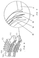
- the electric machine comprises a toothed moving part 1 and stationary tooth parts 2, the moving part 1 moving in the direction indicated by the arrow 3.
- the closed magnetic circuit of the machine is not shown in this schematic representation but would be closed in such a manner that the general direction of magnetic flux would be as indicated by the arrows 4.
- the magnetic lines of force between the moving part 1 and the stationary parts 2 are indicated. These cause a net force on the moving part 1 attracting it into a position on which it would be in full alignment with the stationary parts 2 on the right hand side of Figure 1. This would be the final position of the moving part 1 in moving from the left hand pair of stationary parts 2 to the right hand pair.
- the magnetic excitation would drop to zero as indicated by the base line 0 - 0 as the leading edge of the moving part 1 commences to leave the first pair of stationary teeth 2 as it commences to move from the position indicated by the dashed and dotted lines 5. It would remain at zero until the leading edge of the moving part 1 just begins to enter the next pair of stationary teeth and would be maintained until the moving part is fully in alignment with the stationary teeth 2 whereafter it would again drop to zero.
- Two further sets of such components would be provided with the moving parts staggered, the first set in a position corresponding with that indicated by the dashed and dotted lines 5, the second set by the position indicated by the dashed line 6 and the third set by the solid line 1.
- the magnetic excitation may be supplied by means of suitable windings being given a suitable pulsed d.c. supply as indicated in Figure 1.
- suitable solid state switching circuitry would be provided.
- Such a three phase pulsed supply is indicated schematically by the additional square waves illustrated in dashed and dotted lines and in dotted lines respectively.
- the proportions of the width of the tooth as shown in Figure 1 to the air gap as shown in Figure 1 has been chosen in this Figure for purposes of convenience of illustration but may be chosen to suit the speed needs of a particular application. Since the air gap will generally be made as small as possible so as to provide effective magnetic circuits of minimum reluctance this will allow making the teeth relatively narrow and therefore of large number which in turn will allow the provision of a very high torque when required for a low speed machine. The upper limit to the number of teeth will be reached when the tooth widths are of the order of 5 times the air gap length.
- Figure 2 shows theoretically desirable current profiles for a two phase machine 100 over one completion rotation of the rotor 60,62. Only two phases 101,102 are drawn, further phases being analogous could be used.
- FIG 3 shows in principle the electric circuitry to achieve this current supply.
- An original basic current source at approximately 300 volts is indicated in principle by the battery 40 which is fed to the motor.
- the two phases are drawn, the switching circuitry for these phases is also shown.
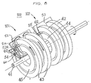
- Figures 4 to 8 show a motor in accordance with the preferred embodiment of the invention to which the graph shown in Figure 2 and the circuit diagram shown in Figure 3 apply.
- each of the two paired phase windings are shown being phase 102, at winding 42 and winding 44 and phase 101 at winding 43 and winding 45, each of these windings being a single continuous spool winding.
- the current source 41 shown in Figure 3 thus supplies current to each of the phases in accordance with control exercised by the FET's S1 working p S2 for phase 102, and q S2 for phase 101.
- the electrical paramaters are designed so that when each FET switches on, the current rise as indicated by the portion 48 in Figure 2 in the case of phase 1 in Figure 2 (which is phase 102 in Figures 4 and 8) is as fast as possible until the plateau 49 is reached, which is then maintained by the constant current source until the FET is switched off with the current fall as indicated by the portion 50 being again as fast as possible.
- Phase 2 shown in Figure 2 is phase 101 in Figures 4 and 8.
- the value of the current plateau 49 is selected to provide the correct degree of magnetisation of the magnetic circuits 52/54 of phase 101 and 53/55 of phase 102.
- 1,4 Tesla could be a design figure.
- the magnetic circuits may be thickened at the area 51A as compared with the width of the circuits at the area 52A.
- the teeth are made up of laminations (not shown) to minimise eddy current losses, Figure 4 showing how each lamination is of E-cross sectional shape.
- Figures 4 and 5 also show the unusual and valuable feature of the machine in accordance with this invention, namely that in the manufacturing process the spool windings, for example 42, are not wound on to the magnetic core as in conventional practice but instead are first wound in a former and thereafer the magnetic materials in the form of the multiplicity of teeth laminations are added to the winding. This greatly simplifies the manufacturing process and lends it to automated assembly by industrial robots.
- the inductive energy is discharged via a diode p D2 in the case of phase 1, a diode q D2 in the case of phase 2 and so on.
- the discharged energy is returned to the source where the energy is usefully returned to the system.
- the control of the switching of the FET's for the phases can be derived from signals delivered by the auxiliary coils for each phase.
- the auxiliary coils are best located as near to the rotor as possible thus improving the signal which will supply the necessary threshold values to switch the FET's. These auxiliary coils thus provide the necessary measurement of shaft position for control of the switching and optical commutation is not needed. However, in principle other techniques of commutation can be resorted to.
- S1 opens when current reaches set upper limit.
- D1 freewheel diode
- S1 closes when current falls below lower limit.
- Current builds up to upper limit and again interrupts S1.
- Upper and lower limits are continuously adjustable giving full control of average current through coils.
- Commutation signals select p S2 or q S2 according to position of rotor thereby giving torque on required direction. Magnetic field energy is supplied on first closure of S1 and is returned to battery on opening of p S2 or q S2 at end of each phase's cycle.
- Commutation signals reverse phase to p S2 and q S2.
- Initial closure of S1 and p S2 or q S2 creates magnetic field which provides counter torque.
- M coils p S2 or q S2 opens when current exceeds another set limit and energy is fed back via flyback diode p D2 or q D2 to the battery.
- Figures 6 and 7 show structures for providing commutation signals, comprising mounted on the composite bonded coil 11 a reference foil 12, isolating tape 13, capacitance foil 14 of toothed shape phase shifted relative to the machine teeth 52 and isolator/bonding tape 15.
- the magnetisation of the magnetic material is not reversed in direction but merely oscillates between zero or a lower value and the maximum magnetisation value. This, much reduces the hysteresis loss associated with conventional electric machines.
- the magnetisation is achieved by means of pulsed direct current or DC rather than alternating current or AC.
- Figure 5 shows how the inter-tooth width is greater than the tooth width, a feature made possible by the use of the four phases.
- the ratio of tooth pitch divided by tooth width can be increased as the number of phases is increased.
- Figure 4 shows an arrangement in which four phases are attained but it will be appreciated that further phases can be incorporated, for example, by extending the stator and rotor along the shaft 61 of the machine. It will also be appreciated that a limited amount of flux leakage from one phase to the other does occur but theoretical considerations indicate and practical tests have confirmed that this is not a problem and interference is limited to second order levels of magnitude.
Landscapes
- Engineering & Computer Science (AREA)
- Power Engineering (AREA)
- Physics & Mathematics (AREA)
- Chemical & Material Sciences (AREA)
- Combustion & Propulsion (AREA)
- Electromagnetism (AREA)
- Synchronous Machinery (AREA)
- Permanent Magnet Type Synchronous Machine (AREA)
- Reciprocating, Oscillating Or Vibrating Motors (AREA)
- Electrical Discharge Machining, Electrochemical Machining, And Combined Machining (AREA)
- Control Of Multiple Motors (AREA)
- Iron Core Of Rotating Electric Machines (AREA)
Claims (18)
- Elektrische Reluktanzmaschine (100) mit Mehrfachphasenanordnung (101,102), Kastenwicklung (43,45/42,44) zur Schaffung einer elektrischen Erregung in jeder Phase, magnetischen Kreisen in jeder Phase, einschließlich eines dünnen Rotors oder bewegenden Teiles (60,62) mit gezahnten Gebilden und elektrischen Stromschaltmitteln (S₁,P,Q) zur synchronisierten Steuerung des Stromes in jeder Kastenwindung, wobei der Stator der Maschine eine Mehrzahl getrennter geschlossener magnetischer Kreise (52/54,53/55) für jede Phase besitzt,
dadurch gekennzeichnet,
daß die Achse jeder Kastenwindung mit der Drehachse des Rotors oder bewegenden Teiles übereinstimmt und in einer Fläche im rechten Winkel zur Rotationsachse des Rotors oder bewegenden Teiles liegt und daß sämtliche magnetischen Kreise in jeder Phase gleichzeitig durch die Kastenwindungen dieser Phase erregt werden, wobei der Stator mit Zahngebilden der gleichen Teilung wie die Teilung der Zahngebilde des Rotors oder bewegenden Teiles eingreift. - Elektrische Maschine gemäß Anspruch 1, worin die "dünne" Dimension des Rotors oder bewegenden Teiles (60,62) weniger als 1/10 des Drehradius des Rotors oder bewegenden Teiles beträgt.
- Elektrische Maschine gemäß Anspruch 1 oder 2, worin die magnetischen Kreise (52/54,53/55) aus Lamellenpaketen aufgebaut sind, welche in Flächen parallel zur Drehachse der Rotationsmaschine liegen.
- Elektrische Maschine gemäß einem der Ansprüche 1 bis 3, worin das Schaltmittel ein doppelseitig schaltender Leistungsverstärker ist.
- Elektrische Maschine gemäß einem der Ansprüche 1 bis 4, worin der Rotor oder das bewegende Teil (60,62) in seiner Dimension im rechten Winkel zur Bewegungsrichtung und in der allgemeinen Richtung der Kraftlinien nicht mehr als 10 Luftspaltlängen beträgt.
- Elektrische Maschine gemäß einem der Ansprüche 1 bis 5, worin die Zahnbreite der Zahngebilde zwischen zwei- und achtmal der Luftspaltendimension entspricht.
- Elektrische Maschine gemäß Anspruch 6, worin die Zahnbreite der Zahngebilde etwa das fünffache der Luftspaltdimension beträgt.
- Elektrische Maschine gemäß einem der Ansprüche 1 bis 7, worin die Zahngebilde so ausgebildet sind, daß die Linearität zwischen Kraft/Drehmoment und Verlagerung erhöht wird.
- Elektrische Maschine gemäß einem der Ansprüche 1 bis 8, die wenigstens in einer Zweiphasenanordnung ausgeführt ist und zwei oder mehr magnetische Kreise, einen für jede Phase, besitzt.
- Elektrische Maschine gemäß Anspruch 9, die in einer Vierphasenanordnung ausgebildet ist.
- Elektrische Maschine gemäß Anspruch 9 oder 10, worin jede Phase axial versetzt längs der Achse des Rotors oder bewegenden Teiles (60,62) angeordnet ist.
- Elektrische Maschine gemäß Anspruch 9, 10 oder 11, worin das Verhältnis von Zahnteilung zur Umfangsbreite der Zähne der Zahngebilde die Anzahl der Phasen nicht überschreitet.
- Elektrische Maschine gemäß einem der Ansprüche 1 bis 9, worin die Anzahl der Zähne der Zahngebilde zwischen 50 und 2000 gewählt ist.
- Elektrische Maschine gemäß Anspruch 12 mit einer endgültigen Ausgangs- oder Eingangsachse ohne zwischengelagertes Getriebe oder sonstige Geschwindigkeitsanpassungsmittel.
- Elektrische Maschine gemäß Anspruch 4 oder 4 und einem der Ansprüche 5 bis 10, worin der doppelseitige Verstärker hinsichtlich Frequenz und Zeitfolge durch Messung der Verlagerung des Rotors oder bewegenden Teiles (60,62) in Bezug auf den Stator gesteuert ist.
- Elektrische Maschine gemäß einem der Ansprüche 1 bis 15, worin der Rotor oder das bewegende Teil (60,62) becherförmig ist, wobei der Rand des Bechers mit den Zähnen der Zahngebilde des Rotors oder bewegenden Teiles ausgestattet ist.
- Elektrische Maschine gemäß Anspruch 1, 5 oder 10, welches eingerichtet ist, um in solenoidartiger Weise mittels zweier kammartiger Zahneinrichtungen zu arbeiten, die in einander eingreifen und im Hub der Maschine um eine Zahnbreite bewegend sind.
- Elektrische Reluktanzmaschine gemäß Anspruch 15, worin Strukturen vorgesehen sind zur Lieferung von Kommutationsfrequenz- und Zeitfolgesignalen mit einer auf der Kastenwindung angebrachten Bezugsfolie (12), Isolierband (13) und Kapazitanzfolie (14) gezahnter Form und phasenverschoben in Bezug auf die Maschinenzahnung (52) und das Isolier/Verbindungsband (15).
Priority Applications (6)
| Application Number | Priority Date | Filing Date | Title |
|---|---|---|---|
| ZA873618A ZA873618B (en) | 1986-02-21 | 1987-05-20 | Electric machines |
| DE88310447T DE3884397T2 (de) | 1988-11-07 | 1988-11-07 | Elektrische Maschine. |
| AT88310447T ATE95013T1 (de) | 1988-11-07 | 1988-11-07 | Elektrische maschine. |
| EP88310447A EP0367870B1 (de) | 1988-11-07 | 1988-11-07 | Elektrische Maschine |
| ES88310447T ES2045145T3 (es) | 1988-11-07 | 1988-11-07 | Maquinas electricas |
| US07/269,264 US4970421A (en) | 1988-11-07 | 1988-11-09 | Electric machines |
Applications Claiming Priority (1)
| Application Number | Priority Date | Filing Date | Title |
|---|---|---|---|
| EP88310447A EP0367870B1 (de) | 1988-11-07 | 1988-11-07 | Elektrische Maschine |
Publications (2)
| Publication Number | Publication Date |
|---|---|
| EP0367870A1 EP0367870A1 (de) | 1990-05-16 |
| EP0367870B1 true EP0367870B1 (de) | 1993-09-22 |
Family
ID=8200278
Family Applications (1)
| Application Number | Title | Priority Date | Filing Date |
|---|---|---|---|
| EP88310447A Expired - Lifetime EP0367870B1 (de) | 1986-02-21 | 1988-11-07 | Elektrische Maschine |
Country Status (5)
| Country | Link |
|---|---|
| US (1) | US4970421A (de) |
| EP (1) | EP0367870B1 (de) |
| AT (1) | ATE95013T1 (de) |
| DE (1) | DE3884397T2 (de) |
| ES (1) | ES2045145T3 (de) |
Cited By (1)
| Publication number | Priority date | Publication date | Assignee | Title |
|---|---|---|---|---|
| RU2402861C1 (ru) * | 2006-11-17 | 2010-10-27 | Уэдж Глобаль, С.Л. | Линейный вентильно-индукторный электродвигатель-генератор |
Families Citing this family (9)
| Publication number | Priority date | Publication date | Assignee | Title |
|---|---|---|---|---|
| US5180955A (en) * | 1990-10-11 | 1993-01-19 | International Business Machines Corporation | Positioning apparatus |
| JPH05199704A (ja) * | 1991-08-08 | 1993-08-06 | General Electric Co <Ge> | 電気アクチュエータ・モータ |
| DE4446547A1 (de) * | 1993-12-31 | 1995-07-06 | Bernhard Schaefer Werkzeug Und | Vorrichtung zum Verbinden eines Drahtes mit einem Kontaktelement und Verfahren zum Betreiben einer solchen Vorrichtung |
| JP3084220B2 (ja) * | 1995-12-21 | 2000-09-04 | 多摩川精機株式会社 | ハイブリッド型ステップモータ |
| DE19846872B4 (de) * | 1998-10-12 | 2006-06-08 | Sew-Eurodrive Gmbh & Co. Kg | Linearer geschalteter Reluktanzmotor und Verfahren zum Betreiben eines linearen geschalteten Reluktanzmotors |
| ATE266272T1 (de) * | 1999-07-05 | 2004-05-15 | Minebea Co Ltd | Stellantrieb mit begrenztem drehwinkel |
| DE60236926D1 (de) * | 2001-05-08 | 2010-08-19 | Univ Aalborg | Transversalflussmaschine mit einem stator aus e-förmigen laminaten |
| GB2448928B (en) | 2007-05-04 | 2009-12-09 | Dynamic Dinosaurs Bv | Power transmission system for use with downhole equipment |
| DE102018217513A1 (de) * | 2018-10-12 | 2020-04-16 | Festo Se & Co. Kg | Linearreluktanzmotor |
Family Cites Families (5)
| Publication number | Priority date | Publication date | Assignee | Title |
|---|---|---|---|---|
| US2627040A (en) * | 1950-08-01 | 1953-01-27 | Hansen Siegfried | Stepping motor |
| DE2022750A1 (de) * | 1970-05-09 | 1971-11-25 | Anker Werke Ag | Verfahren und Einrichtung zur Einstellung von Schrittmotoren auf eine definierte Schrittstellung |
| US4638195A (en) * | 1985-02-11 | 1987-01-20 | Lin Ted T | Multiple-pole stepping motor |
| EP0240204A3 (de) * | 1986-04-03 | 1988-10-19 | Adept Technology, Inc. | Schrittschaltmotor mit veränderbarer Reluktanz |
| US4754178A (en) * | 1986-04-29 | 1988-06-28 | Mcs, Inc. | Stepper motor |
-
1988
- 1988-11-07 AT AT88310447T patent/ATE95013T1/de not_active IP Right Cessation
- 1988-11-07 EP EP88310447A patent/EP0367870B1/de not_active Expired - Lifetime
- 1988-11-07 DE DE88310447T patent/DE3884397T2/de not_active Expired - Fee Related
- 1988-11-07 ES ES88310447T patent/ES2045145T3/es not_active Expired - Lifetime
- 1988-11-09 US US07/269,264 patent/US4970421A/en not_active Expired - Fee Related
Cited By (1)
| Publication number | Priority date | Publication date | Assignee | Title |
|---|---|---|---|---|
| RU2402861C1 (ru) * | 2006-11-17 | 2010-10-27 | Уэдж Глобаль, С.Л. | Линейный вентильно-индукторный электродвигатель-генератор |
Also Published As
| Publication number | Publication date |
|---|---|
| ES2045145T3 (es) | 1994-01-16 |
| DE3884397D1 (de) | 1993-10-28 |
| EP0367870A1 (de) | 1990-05-16 |
| ATE95013T1 (de) | 1993-10-15 |
| US4970421A (en) | 1990-11-13 |
| DE3884397T2 (de) | 1994-04-21 |
Similar Documents
| Publication | Publication Date | Title |
|---|---|---|
| US5925965A (en) | Axial flux reluctance machine with two stators driving a rotor | |
| US4794286A (en) | Variable reluctance stepper motor | |
| EP0504093B1 (de) | Geschalteter Reluktanzmotor mit aus isolierten Segmenten bestehendem Rotor | |
| US4857786A (en) | Structure of stepping motor and method of driving the stepping motor | |
| US4761590A (en) | Electric motor | |
| EP0559818B1 (de) | Kommutierter mehrphasenreluktanzmotor | |
| US5175457A (en) | Linear motor or alternator plunger configuration using variable magnetic properties for center row and outer rows of magnets | |
| Shakal et al. | A permanent magnet AC machine structure with true field weakening capability | |
| EP1359660B1 (de) | Geschalteter Reluktanzmotor | |
| EP1198055B1 (de) | Linearmotor, Steuerungssystem, Antriebssystem und Herstellungsverfahren dafür | |
| EP0367870B1 (de) | Elektrische Maschine | |
| JPH08214519A (ja) | 永久磁石を用いた両突極性電動発電機 | |
| US20080030092A1 (en) | Hybrid Electric Reluctance Motor | |
| Corda et al. | Linear switched reluctance actuator | |
| US5545936A (en) | C-stator type segmented zoned field dc-motor | |
| CN101567588B (zh) | 一种圆柱型直线电机 | |
| Ghaffarpour et al. | Analysis of an e-core permanent magnet switched reluctance motor | |
| Pollock et al. | Switched reluctance drives: a comparative evaluation | |
| JP4293602B2 (ja) | 電気機械 | |
| WO1994026020A1 (en) | Linear actuator | |
| CN86105770A (zh) | 四相四线星形联接的开关式磁阻电机 | |
| JPS6192158A (ja) | リニアモ−タ | |
| CN1182302A (zh) | 高效多态电动机 | |
| EP0240204A2 (de) | Schrittschaltmotor mit veränderbarer Reluktanz | |
| US20240396415A1 (en) | Rotational Linear Motor |
Legal Events
| Date | Code | Title | Description |
|---|---|---|---|
| PUAI | Public reference made under article 153(3) epc to a published international application that has entered the european phase |
Free format text: ORIGINAL CODE: 0009012 |
|
| AK | Designated contracting states |
Kind code of ref document: A1 Designated state(s): AT BE CH DE ES FR GB GR IT LI LU NL SE |
|
| 17P | Request for examination filed |
Effective date: 19901109 |
|
| 17Q | First examination report despatched |
Effective date: 19920617 |
|
| GRAA | (expected) grant |
Free format text: ORIGINAL CODE: 0009210 |
|
| AK | Designated contracting states |
Kind code of ref document: B1 Designated state(s): AT BE CH DE ES FR GB GR IT LI LU NL SE |
|
| REF | Corresponds to: |
Ref document number: 95013 Country of ref document: AT Date of ref document: 19931015 Kind code of ref document: T |
|
| REF | Corresponds to: |
Ref document number: 3884397 Country of ref document: DE Date of ref document: 19931028 |
|
| ITF | It: translation for a ep patent filed | ||
| REG | Reference to a national code |
Ref country code: ES Ref legal event code: FG2A Ref document number: 2045145 Country of ref document: ES Kind code of ref document: T3 |
|
| ET | Fr: translation filed | ||
| REG | Reference to a national code |
Ref country code: GR Ref legal event code: FG4A Free format text: 3010202 |
|
| EPTA | Lu: last paid annual fee | ||
| PLBE | No opposition filed within time limit |
Free format text: ORIGINAL CODE: 0009261 |
|
| STAA | Information on the status of an ep patent application or granted ep patent |
Free format text: STATUS: NO OPPOSITION FILED WITHIN TIME LIMIT |
|
| 26N | No opposition filed | ||
| PGFP | Annual fee paid to national office [announced via postgrant information from national office to epo] |
Ref country code: LU Payment date: 19941001 Year of fee payment: 7 |
|
| PGFP | Annual fee paid to national office [announced via postgrant information from national office to epo] |
Ref country code: FR Payment date: 19941007 Year of fee payment: 7 |
|
| PGFP | Annual fee paid to national office [announced via postgrant information from national office to epo] |
Ref country code: AT Payment date: 19941013 Year of fee payment: 7 |
|
| PGFP | Annual fee paid to national office [announced via postgrant information from national office to epo] |
Ref country code: SE Payment date: 19941014 Year of fee payment: 7 Ref country code: GB Payment date: 19941014 Year of fee payment: 7 |
|
| PGFP | Annual fee paid to national office [announced via postgrant information from national office to epo] |
Ref country code: BE Payment date: 19941020 Year of fee payment: 7 |
|
| PGFP | Annual fee paid to national office [announced via postgrant information from national office to epo] |
Ref country code: DE Payment date: 19941024 Year of fee payment: 7 |
|
| PGFP | Annual fee paid to national office [announced via postgrant information from national office to epo] |
Ref country code: CH Payment date: 19941025 Year of fee payment: 7 |
|
| PGFP | Annual fee paid to national office [announced via postgrant information from national office to epo] |
Ref country code: ES Payment date: 19941104 Year of fee payment: 7 |
|
| PGFP | Annual fee paid to national office [announced via postgrant information from national office to epo] |
Ref country code: GR Payment date: 19941116 Year of fee payment: 7 |
|
| PGFP | Annual fee paid to national office [announced via postgrant information from national office to epo] |
Ref country code: NL Payment date: 19941130 Year of fee payment: 7 |
|
| EAL | Se: european patent in force in sweden |
Ref document number: 88310447.3 |
|
| PG25 | Lapsed in a contracting state [announced via postgrant information from national office to epo] |
Ref country code: LU Free format text: LAPSE BECAUSE OF NON-PAYMENT OF DUE FEES Effective date: 19951107 Ref country code: GB Effective date: 19951107 Ref country code: AT Effective date: 19951107 |
|
| PG25 | Lapsed in a contracting state [announced via postgrant information from national office to epo] |
Ref country code: SE Effective date: 19951108 Ref country code: ES Free format text: LAPSE BECAUSE OF EXPIRATION OF PROTECTION Effective date: 19951108 |
|
| PG25 | Lapsed in a contracting state [announced via postgrant information from national office to epo] |
Ref country code: LI Effective date: 19951130 Ref country code: CH Effective date: 19951130 Ref country code: BE Effective date: 19951130 |
|
| BERE | Be: lapsed |
Owner name: KRITZINGER CORNELIUS ALEWYN JOHANNES Effective date: 19951130 |
|
| PG25 | Lapsed in a contracting state [announced via postgrant information from national office to epo] |
Ref country code: GR Free format text: THE PATENT HAS BEEN ANNULLED BY A DECISION OF A NATIONAL AUTHORITY Effective date: 19960531 |
|
| PG25 | Lapsed in a contracting state [announced via postgrant information from national office to epo] |
Ref country code: NL Effective date: 19960601 |
|
| GBPC | Gb: european patent ceased through non-payment of renewal fee |
Effective date: 19951107 |
|
| REG | Reference to a national code |
Ref country code: CH Ref legal event code: PL |
|
| PG25 | Lapsed in a contracting state [announced via postgrant information from national office to epo] |
Ref country code: FR Effective date: 19960731 |
|
| REG | Reference to a national code |
Ref country code: GR Ref legal event code: MM2A Free format text: 3010202 |
|
| NLV4 | Nl: lapsed or anulled due to non-payment of the annual fee |
Effective date: 19960601 |
|
| PG25 | Lapsed in a contracting state [announced via postgrant information from national office to epo] |
Ref country code: DE Effective date: 19960801 |
|
| EUG | Se: european patent has lapsed |
Ref document number: 88310447.3 |
|
| REG | Reference to a national code |
Ref country code: FR Ref legal event code: ST |
|
| REG | Reference to a national code |
Ref country code: ES Ref legal event code: FD2A Effective date: 20010301 |
|
| PG25 | Lapsed in a contracting state [announced via postgrant information from national office to epo] |
Ref country code: IT Free format text: LAPSE BECAUSE OF NON-PAYMENT OF DUE FEES;WARNING: LAPSES OF ITALIAN PATENTS WITH EFFECTIVE DATE BEFORE 2007 MAY HAVE OCCURRED AT ANY TIME BEFORE 2007. THE CORRECT EFFECTIVE DATE MAY BE DIFFERENT FROM THE ONE RECORDED. Effective date: 20051107 |