EP0367878B1 - Lentille multifocale à décalage de phase par palier - Google Patents
Lentille multifocale à décalage de phase par palier Download PDFInfo
- Publication number
- EP0367878B1 EP0367878B1 EP88310561A EP88310561A EP0367878B1 EP 0367878 B1 EP0367878 B1 EP 0367878B1 EP 88310561 A EP88310561 A EP 88310561A EP 88310561 A EP88310561 A EP 88310561A EP 0367878 B1 EP0367878 B1 EP 0367878B1
- Authority
- EP
- European Patent Office
- Prior art keywords
- lens
- phase plate
- focal point
- multiple focal
- designing
- Prior art date
- Legal status (The legal status is an assumption and is not a legal conclusion. Google has not performed a legal analysis and makes no representation as to the accuracy of the status listed.)
- Expired - Lifetime
Links
Images


Classifications
-
- G—PHYSICS
- G02—OPTICS
- G02B—OPTICAL ELEMENTS, SYSTEMS OR APPARATUS
- G02B5/00—Optical elements other than lenses
- G02B5/18—Diffraction gratings
- G02B5/1876—Diffractive Fresnel lenses; Zone plates; Kinoforms
- G02B5/189—Structurally combined with optical elements not having diffractive power
- G02B5/1895—Structurally combined with optical elements not having diffractive power such optical elements having dioptric power
-
- A—HUMAN NECESSITIES
- A61—MEDICAL OR VETERINARY SCIENCE; HYGIENE
- A61F—FILTERS IMPLANTABLE INTO BLOOD VESSELS; PROSTHESES; DEVICES PROVIDING PATENCY TO, OR PREVENTING COLLAPSING OF, TUBULAR STRUCTURES OF THE BODY, e.g. STENTS; ORTHOPAEDIC, NURSING OR CONTRACEPTIVE DEVICES; FOMENTATION; TREATMENT OR PROTECTION OF EYES OR EARS; BANDAGES, DRESSINGS OR ABSORBENT PADS; FIRST-AID KITS
- A61F2/00—Filters implantable into blood vessels; Prostheses, i.e. artificial substitutes or replacements for parts of the body; Appliances for connecting them with the body; Devices providing patency to, or preventing collapsing of, tubular structures of the body, e.g. stents
- A61F2/02—Prostheses implantable into the body
- A61F2/14—Eye parts, e.g. lenses or corneal implants; Artificial eyes
- A61F2/16—Intraocular lenses
- A61F2/1613—Intraocular lenses having special lens configurations, e.g. multipart lenses; having particular optical properties, e.g. pseudo-accommodative lenses, lenses having aberration corrections, diffractive lenses, lenses for variably absorbing electromagnetic radiation, lenses having variable focus
- A61F2/1616—Pseudo-accommodative, e.g. multifocal or enabling monovision
- A61F2/1618—Multifocal lenses
-
- G—PHYSICS
- G02—OPTICS
- G02B—OPTICAL ELEMENTS, SYSTEMS OR APPARATUS
- G02B3/00—Simple or compound lenses
- G02B3/10—Bifocal lenses; Multifocal lenses
-
- G—PHYSICS
- G02—OPTICS
- G02B—OPTICAL ELEMENTS, SYSTEMS OR APPARATUS
- G02B5/00—Optical elements other than lenses
- G02B5/18—Diffraction gratings
- G02B5/1876—Diffractive Fresnel lenses; Zone plates; Kinoforms
-
- G—PHYSICS
- G02—OPTICS
- G02C—SPECTACLES; SUNGLASSES OR GOGGLES INSOFAR AS THEY HAVE THE SAME FEATURES AS SPECTACLES; CONTACT LENSES
- G02C7/00—Optical parts
- G02C7/02—Lenses; Lens systems ; Methods of designing lenses
- G02C7/04—Contact lenses for the eyes
- G02C7/041—Contact lenses for the eyes bifocal; multifocal
- G02C7/042—Simultaneous type
-
- G—PHYSICS
- G02—OPTICS
- G02C—SPECTACLES; SUNGLASSES OR GOGGLES INSOFAR AS THEY HAVE THE SAME FEATURES AS SPECTACLES; CONTACT LENSES
- G02C7/00—Optical parts
- G02C7/02—Lenses; Lens systems ; Methods of designing lenses
- G02C7/04—Contact lenses for the eyes
- G02C7/041—Contact lenses for the eyes bifocal; multifocal
- G02C7/044—Annular configuration, e.g. pupil tuned
-
- G—PHYSICS
- G02—OPTICS
- G02C—SPECTACLES; SUNGLASSES OR GOGGLES INSOFAR AS THEY HAVE THE SAME FEATURES AS SPECTACLES; CONTACT LENSES
- G02C7/00—Optical parts
- G02C7/02—Lenses; Lens systems ; Methods of designing lenses
- G02C7/06—Lenses; Lens systems ; Methods of designing lenses bifocal; multifocal ; progressive
-
- G—PHYSICS
- G02—OPTICS
- G02C—SPECTACLES; SUNGLASSES OR GOGGLES INSOFAR AS THEY HAVE THE SAME FEATURES AS SPECTACLES; CONTACT LENSES
- G02C2202/00—Generic optical aspects applicable to one or more of the subgroups of G02C7/00
- G02C2202/20—Diffractive and Fresnel lenses or lens portions
Definitions
- This invention relates to a method of designing and fabricating a multiple focal point profiled phase plate.
- a more recent bifocal lens configuration makes use of a zone plate design as described in my U.S. Patent No. 4,210,391, No. 4,338,005 and No. 4,340,283. These designs allow the two different focal powers to be achieved by diffractive effects. However, because these lens designs utilize multiple concentric rings of diameters less than that of the pupil of the eye, as the pupil of the eye opens and closes, only a small number of rings are involved and the relative brightnesses of the two images remain the same.
- An embodiment of a multiple focal power optical device produced by the method comprises: body means having a plurality of annular concentric zones spaced so as to produce a diffractive power; wherein a phase shifting means is incorporated into a least some of the annular zones, the phase shifting means being of a step function nature, causing a substantially constant shift in the optical path length across essentially the entire zone into which it is incorporated.
- An embodiment of the invention employs body means which comprise an optically refracting material.
- the phase shifting means may include the body means together with imbedded contaminants to achieve the desired phase shift, or an excavated portion of the body means.
- the phase shifting means may occupy every alternate zone.
- the invention features the use of phase shifting means that are adjusted so as to cause equal image brightness at each of the focal points of said body means.
- the phase shifting steps may be adjusted so as to create a trifocal with equal image brightnesses at each of the focal points of said body means.
- the phase shifting steps are adjusted so as to cause the lens to focus some wavelengths of light preferentially. It is desirable to have the phase shifting steps adjusted so as to reduce the maximum depths of any blaze or step.
- the invention employs an optical device as a contact lens, a spectacle lens, an intraocular lens implant, or a mirror.
- phase plate wherein a repetitive step is incorporated into the profile, whereby to cause a constant shift in the optical path length across essentially the entire zone into which it is incorporated.
- the phase plate is designed to operate as a multifocal lens in the visible light range.
- such embodiments of the invention design the body means of said phase plate as a contact lens or as a camera lens.
- a multifocal lens we wish to share the incident light between the various focal points. It is important when doing this, that we keep the various image brightnesses at each of the focal points substantially equal in intensity.
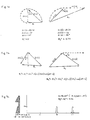
- the amplitude vector z1(1) for light passing through zone 1 is turned ahead by 90 degrees, while the amplitude vector z2(1) for light passing through zone 2 is turned ahead by 180 degrees.
- the phase angle a(1) between the two resultant amplitude vectors is 45 degrees, yielding the image brightness B12 at the 1.0 Diopter focus. All of this is shown in FIG. 7a, where the image brightnesses are calculated as the vector sum of the resultant amplitude vectors z1 and z2. Since we are considering two zones, it is convenient to assign the value 1/2 to the total arc length of the small differential amplitude vectors passing through each zone.
- FIG. 7b shows the light amplitude vectors z1 and z2, representing the light from zone 1 and zone 2 respectively, for each focus separated by an additional phase shift of b degrees.
- the resultant brightnesses B02 at the 1.0 Diopter focus are also shown.
- FIG. 7b we see that as we increase the phase angle b (by increasing the step depth), the dimmer image B, becomes brighter, while the brighter image B0 becomes dimmer.
- the image brightnesses will be equal.
- phase shifting step In this particular case a phase shift of 0.157 wavelengths accomplishes the task, and FIG. 7C shows just such a resultant lens. It should also be noticed that the maximum depth of the facets in this lens is only 0.407 wavelengths deep. Typically, diffractive lenses require phase shifts of 0.5 wavelengths or more. It is an advantage to be able to reduce the required maximum phase shift, since many manufacturing techniques (i.e. ion implantation) are limited in the maximum phase shift they can achieve. It must of course be stated, that this is just one particular example of the use of phase shifting step, and that in general we may choose phase shifting steps other than 0.157 wavelengths.
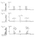
- FIG. 8 shows an example of this type of lens.
- This particular lens is an example of a trifocal with focii of unequal brightnesses.
- a phase shift step of 0.212 wavelengths we are able to construct the equal brightness trifocal of FIG. 9.
- FIG. 10 shows the resulting trifocal.
- An important advantage of this trifocal is its simple step design which allows for easier fabrication, since etching a step is much easier than cutting a blaze in many manufacturing techniques (i.e. ion reactive etching). While the bifocal lens of R. W. Wood is of a simple step design, this is the first trifocal of such a simple design.
- FIG. 11 shows the trifocal complimentary to the one shown in FIG. 10.
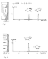
- FIG. 2 shows a portion of a profile of another known phase plate bifocal, and its corresponding graph of brightness vs focal power, showing unequal brightness (i.e. B0 ⁇ B1) at each focal point.
- FIG. 3 shows the profile of a flat lens of zero power, and its corresponding graph of brightness vs focal power, showing a single focal point at infinity (i.e. 0.0 Diopters).
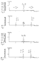
- FIG. 4 shows the profile of a flat lens of zero power, modified as described by R. W. Wood, and its corresponding graph of brightness vs focal power, showing two focal points of equal brightnesses.
- FIG. 5 shows a portion of the profile of a known blazed lens with a single focal power, and its corresponding graph of brightness vs focal power, showing the single focal point.
- FIG. 6 shows a a portion of the profile of the lens of FIG. 5, modified as described by R. W. Wood, and its corresponding graph of brightness vs focal power, showing two focal points of equal brightnesses.
- FIG. 7a depicts a geometrical representation of the light amplitude vectors, passing through the annular zones of the lens of FIG. 2.
- FIG. 7b shows graphically, how the brightnesses B02 and B12 are altered by the introduction of a phase shift of b degrees between zone 1 and zone 2.
- FIGS. 8-14 show portions of profiles of blazed and stepped trifocals, together with their corresponding graphs of brightness vs focal power.
- FIG. 15 is a cross-sectional view of a trifocal lens formed by ion reactive etching of steps.
- FIG. 16 is a cross-sectional view of a trifocal lens formed by ion implanting of blazed steps.
- FIG. 17 is a cross-sectional view of a bifocal mirror formed by plating of steps onto the mirror surface.
- the anterior surface I of a carrier lens or body CL divided into six concentric annular zones, bounded by radii r1-r6, in such a manner as to form a trifocal phase plate.
- the number of zones may be more or less, and six zones was chose merely as an illustrative example.
- the carrier lens or body is constructed according to the usual principles governing the design of an optical lens with the surfaces I and B either spherical, sphero-cylindrical, or of any other appropriate lens design.
- the spherical, sphero-cylindrical, or aspheric power P of the carrier lens depends, according to the standard lens formulas, on the curvatures of the anterior and posterior surfaces I and B respectively, the center thickness CT, and refractive index n of the carrier lens. These parameters are in turn, determined by the intended use of this trifocal phase plate and the materials available.
- the posterior surface B may be shaped so as to minimize off axis optical aberrations if this trifocal phase plate is to be used as a spectacle lens.
- Standard optical materials such as glass, plastic, or any other optical materials, including those used in the manufacture of spectacles, contact lenses, etc. may be used in the fabrication of this and all subsequent embodiments.
- annular zones are uniformly etched to a depth of substantially 0.319/(n-1) wavelengths of light, where n is the index of refraction of the carrier lens. This will of course, cause a phase shift of 0.319 wavelengths of light between adjacent annular zones.
- the spacing of the annular zones is of course given by the zone plate formula for r(k).
- the resultant trifocal in this case will exhibit three focal powers of equal image brightnesses at P-F Diopters, P Diopters, and P + F Diopters.
- the new and important feature of this embodiment, and of all the subsequent embodiments, is the ratio of image brightnesses which are determined by the particular depth of the steps etched into the surface of the lens.
- the depth in this case is given by (b/360)* ⁇ /(n-1) where b is the phase shift in degrees.
- b a different value of b would result in a different embodiment of this invention.
- FIG. 16 Another embodiment of the present invention, which utilizes ion implantation, is shown in FIG. 16, where the zones are formed by ions implanted into the surface of the carrier lens CL, thereby changing the index of refraction of the carrier lens from n to n1.
- the depth of implantation is given by the equation (b/360*) ⁇ /(n-n1).
- the blazes are 0.5/(n-1) wavelengths deep, and the steps are .319/(n-1) wavelengths deep, where n is the index of refraction of the carrier lens CL.
- the carrier lens has been designed with a front surface I, a back surface B, and a focal power P.
- the three focal powers of this lens are P, P+F/2, and P+F.
- FIG. 17 Another embodiment of the present invention, which utilizes an evaporation plating technique, is shown in FIG. 17, where the zones are formed by the plating of additional material D, onto the surface of the carrier lens CL, thereby increasing the light path through the carrier lens.
- the lens CL being bonded to the mirror M, and the thickness of the plating is given by (b/720)* ⁇ /(n1-1), with n1 the index of refraction of the plated material.
Landscapes
- Physics & Mathematics (AREA)
- Health & Medical Sciences (AREA)
- Ophthalmology & Optometry (AREA)
- General Physics & Mathematics (AREA)
- Optics & Photonics (AREA)
- General Health & Medical Sciences (AREA)
- Biomedical Technology (AREA)
- Life Sciences & Earth Sciences (AREA)
- Transplantation (AREA)
- Engineering & Computer Science (AREA)
- Cardiology (AREA)
- Heart & Thoracic Surgery (AREA)
- Vascular Medicine (AREA)
- Oral & Maxillofacial Surgery (AREA)
- Animal Behavior & Ethology (AREA)
- Public Health (AREA)
- Veterinary Medicine (AREA)
- Eyeglasses (AREA)
- Materials For Medical Uses (AREA)
- Superconductors And Manufacturing Methods Therefor (AREA)
- Transition And Organic Metals Composition Catalysts For Addition Polymerization (AREA)
- Absorbent Articles And Supports Therefor (AREA)
Claims (13)
- Procédé de conception et de fabrication d'une lamelle de phase profilée à points focaux multiples, le procédé comprenant les étapes :
de détermination d'une longueur d'onde théorique ;
de détermination des rayons de plusieurs zones annulaires concentriques espacées, d'après la formule :
de détermination des déphasages entre des zones annulaires concentriques adjacentes pour égaliser la luminosité d'image au droit de chacun des points focaux pour la longueur d'onde théorique ;
de fabrication de ladite lamelle de phase profilée à point focaux multiples en formant un moyen de déphasage sous la forme d'une dénivellation répétitive sur l'une des faces (I) d'un corps (CL) de manière à provoquer le décalage de ladite phase déterminée, au droit d'au moins certaines desdites zones annulaires concentriques adjacentes ; caractérisé en ce que la hauteur de la dénivellation répétitive est choisie de façon à entraîner une différence de trajet optique entre lesdites zones adjacentes qui est sensiblement plus grande ou sensiblement moindre que le moitié de la longueur d'onde théorique. - Procédé selon la revendication 1, caractérisé en ce que l'étape de fabrication comprend la formation de parties creusées dans ledit corps (CL).
- Procédé selon les revendications 1 ou 2, caractérisé en ce que la dénivellation répétitive se produit après une zone alternée sur deux.
- Procédé selon les revendications 1, 2 et 3, caractérisé en ce que la dénivellation répétitive est alternée entre des sens contraires dans des zones annulaires concentriques successives pour créer une lamelle de phase profilée à triple point focal.
- Procédé selon l'une quelconque des revendications précédentes, dans lequel la longueur d'onde théorique est dans le domaine visible.
- Procédé selon l'une quelconque des revendications précédentes, dans lequel ledit corps (CL) comprend une matière optiquement réfringente.
- Procédé selon les revendications 5 et 6, comprenant en outre l'étape de conception de la lamelle de phase profilée à point focaux multiples pour utilisation comme lentille de contact.
- Procédé selon les revendications 5 et 6, comprenant en outre l'étape de conception de la lamelle de phase à point focaux multiples pour utilisation comme verre de lunettes.
- Procédé selon les revendications 5 et 6, comprenant en outre l'étape de conception de la lamelle de phase profilée à point focaux multiples pour utilisation comme implant intra-oculaire.
- Procédé selon les revendications 5 et 6, comprenant en outre l'étape de conception de la lamelle de phase profilée à point focaux multiples pour utilisation comme lentille d'appareil photographique.
- Procédé selon l'une quelconque des revendications précédentes, dans lequel l'étape de fabrication comprend la formation d'un miroir (M) sur une face dudit corps (CL).
- Procédé selon l'une quelconque des revendications 1 à 4 précédentes, dans lequel l'étape de fabrication comprend la formation d'un miroir (M) sur une face dudit corps (CL).
- Utilisation d'une lamelle de phase profilée à point focaux multiples obtenue par le procédé selon l'une quelconque des revendications précédentes, à la longueur d'onde théorique.
Priority Applications (7)
| Application Number | Priority Date | Filing Date | Title |
|---|---|---|---|
| US06/863,069 US5017000A (en) | 1986-05-14 | 1986-05-14 | Multifocals using phase shifting |
| AT88310561T ATE126900T1 (de) | 1986-05-14 | 1988-11-10 | Multifokale linse mit phasenverschiebenden stufen. |
| EP88310561A EP0367878B1 (fr) | 1986-05-14 | 1988-11-10 | Lentille multifocale à décalage de phase par palier |
| CA000582735A CA1318799C (fr) | 1986-05-14 | 1988-11-10 | Lentilles a foyers multiples utilisant des etapes de dephasage |
| ES88310561T ES2075836T3 (es) | 1986-05-14 | 1988-11-10 | Lentes multifocales que utilizan escalones de desplazamiento. |
| AU25020/88A AU623343B2 (en) | 1986-05-14 | 1988-11-10 | A multiple focal point profiled phase plate |
| DE3854350T DE3854350T2 (de) | 1986-05-14 | 1988-11-10 | Multifokale Linse mit phasenverschiebenden Stufen. |
Applications Claiming Priority (2)
| Application Number | Priority Date | Filing Date | Title |
|---|---|---|---|
| US06/863,069 US5017000A (en) | 1986-05-14 | 1986-05-14 | Multifocals using phase shifting |
| EP88310561A EP0367878B1 (fr) | 1986-05-14 | 1988-11-10 | Lentille multifocale à décalage de phase par palier |
Publications (2)
| Publication Number | Publication Date |
|---|---|
| EP0367878A1 EP0367878A1 (fr) | 1990-05-16 |
| EP0367878B1 true EP0367878B1 (fr) | 1995-08-23 |
Family
ID=26117093
Family Applications (1)
| Application Number | Title | Priority Date | Filing Date |
|---|---|---|---|
| EP88310561A Expired - Lifetime EP0367878B1 (fr) | 1986-05-14 | 1988-11-10 | Lentille multifocale à décalage de phase par palier |
Country Status (7)
| Country | Link |
|---|---|
| US (1) | US5017000A (fr) |
| EP (1) | EP0367878B1 (fr) |
| AT (1) | ATE126900T1 (fr) |
| AU (1) | AU623343B2 (fr) |
| CA (1) | CA1318799C (fr) |
| DE (1) | DE3854350T2 (fr) |
| ES (1) | ES2075836T3 (fr) |
Cited By (1)
| Publication number | Priority date | Publication date | Assignee | Title |
|---|---|---|---|---|
| US8562675B2 (en) | 2008-07-15 | 2013-10-22 | Novartis Ag | Extended depth of focus (EDOF) lens to increase pseudo-accommodation by utilizing pupil dynamics |
Families Citing this family (94)
| Publication number | Priority date | Publication date | Assignee | Title |
|---|---|---|---|---|
| US5201762A (en) * | 1987-05-20 | 1993-04-13 | Hauber Frederick A | Intraocular archromatic lens |
| AU622420B2 (en) * | 1988-07-20 | 1992-04-09 | Allen L. Cohen | Multifocal optical device |
| US5044706A (en) * | 1990-02-06 | 1991-09-03 | Hughes Aircraft Company | Optical element employing aspherical and binary grating optical surfaces |
| US5117306A (en) * | 1990-07-17 | 1992-05-26 | Cohen Allen L | Diffraction bifocal with adjusted chromaticity |
| US5229797A (en) * | 1990-08-08 | 1993-07-20 | Minnesota Mining And Manufacturing Company | Multifocal diffractive ophthalmic lenses |
| GB2256500A (en) * | 1991-05-03 | 1992-12-09 | Minnesota Mining & Mfg | Diffractive mirror having diffractive zones seperated by optical steps |
| DE4134518A1 (de) * | 1991-10-18 | 1993-04-22 | Adatomed Pharma & Med | Ophthalmische linse |
| US5245366A (en) * | 1991-10-31 | 1993-09-14 | Svochak Jan B | Bifocal contact lens and method of making same |
| US5260828A (en) * | 1992-03-27 | 1993-11-09 | Polaroid Corporation | Methods and means for reducing temperature-induced variations in lenses and lens devices |
| US5344447A (en) * | 1992-11-12 | 1994-09-06 | Massachusetts Institute Of Technology | Diffractive trifocal intra-ocular lens design |
| US5760871A (en) * | 1993-01-06 | 1998-06-02 | Holo-Or Ltd. | Diffractive multi-focal lens |
| JP2532818B2 (ja) * | 1993-02-01 | 1996-09-11 | 松下電器産業株式会社 | 対物レンズおよび光ヘッド装置 |
| US5815293A (en) * | 1993-02-01 | 1998-09-29 | Matsushita Electric Industrial Co., Ltd. | Compound objective lens having two focal points |
| US5631762A (en) * | 1993-06-04 | 1997-05-20 | Hitachi Koki Co., Ltd. | Multi-beam generating element and optical printing apparatus therewith |
| US5895422A (en) * | 1993-06-17 | 1999-04-20 | Hauber; Frederick A. | Mixed optics intraocular achromatic lens |
| US5543966A (en) * | 1993-12-29 | 1996-08-06 | Eastman Kodak Company | Hybrid refractive/diffractive achromatic camera lens |
| US5581405A (en) * | 1993-12-29 | 1996-12-03 | Eastman Kodak Company | Hybrid refractive/diffractive achromatic camera lens and camera using such |
| CN1132025C (zh) * | 1994-03-17 | 2003-12-24 | 比福康光学研究和发展股份有限公司 | 分区透镜和分区反射镜 |
| US5699142A (en) * | 1994-09-01 | 1997-12-16 | Alcon Laboratories, Inc. | Diffractive multifocal ophthalmic lens |
| US5715031A (en) * | 1995-05-04 | 1998-02-03 | Johnson & Johnson Vision Products, Inc. | Concentric aspheric multifocal lens designs |
| DE19619478A1 (de) * | 1996-05-14 | 1997-11-20 | Sick Ag | Optische Anordnung mit diffraktivem optischem Element |
| EP0838812B1 (fr) * | 1996-10-23 | 2003-04-09 | Konica Corporation | Procédé d'enregistrement et de reproduction d'un disque optique, lentille d'objectif et méthode de réalisation de cette lentille |
| TW525158B (en) | 1997-03-13 | 2003-03-21 | Hitachi Ltd | Objective lens and optical head using the same |
| JP3472097B2 (ja) * | 1997-08-20 | 2003-12-02 | キヤノン株式会社 | 回折光学素子及びそれを用いた光学系 |
| US6158862A (en) * | 1997-12-04 | 2000-12-12 | Alcon Laboratories, Inc. | Method of reducing glare associated with multifocal ophthalmic lenses |
| US6392805B1 (en) * | 1998-03-23 | 2002-05-21 | Minolta Co., Ltd. | Diffractive optical element and an optical system having a diffractive optical element |
| JP3827860B2 (ja) * | 1998-03-31 | 2006-09-27 | パイオニア株式会社 | 対物レンズ及び光ピックアップ装置 |
| US6120148A (en) * | 1998-10-05 | 2000-09-19 | Bifocon Optics Gmbh | Diffractive lens |
| DE29902409U1 (de) * | 1999-02-11 | 1999-05-20 | Werkhaus Design + Produktion GmbH, 29562 Suhlendorf | Fliegenaugenbrille |
| DE19926512A1 (de) * | 1999-06-10 | 2000-12-14 | Acritec Gmbh | Intraokularlinse |
| RU2186417C2 (ru) * | 2000-02-22 | 2002-07-27 | Институт автоматики и электрометрии СО РАН | Дифракционная интраокулярная линза |
| JP3486606B2 (ja) * | 2000-09-08 | 2004-01-13 | キヤノン株式会社 | 回折光学素子およびそれを用いた光学系 |
| US7245407B2 (en) | 2002-06-10 | 2007-07-17 | Matsushita Electric Industrial Co., Ltd. | Complex objective lens compatible with information media of different thicknesses |
| US7896916B2 (en) | 2002-11-29 | 2011-03-01 | Amo Groningen B.V. | Multifocal ophthalmic lens |
| SE0203564D0 (sv) | 2002-11-29 | 2002-11-29 | Pharmacia Groningen Bv | Multifocal opthalmic lens |
| US6951391B2 (en) * | 2003-06-16 | 2005-10-04 | Apollo Optical Systems Llc | Bifocal multiorder diffractive lenses for vision correction |
| WO2005001553A1 (fr) | 2003-06-30 | 2005-01-06 | Fiala Werner J | Lentille intra-oculaire ou lentille de contact a foyer de grande profondeur |
| US20050027354A1 (en) * | 2003-07-28 | 2005-02-03 | Advanced Medical Optics, Inc. | Primary and supplemental intraocular lens |
| FR2872590B1 (fr) * | 2004-07-02 | 2006-10-27 | Essilor Int | Procede de realisation d'un verre ophtalmique et composant optique adapte pour la mise en oeuvre de ce procede |
| US7025456B2 (en) * | 2004-08-20 | 2006-04-11 | Apollo Optical Systems, Llc | Diffractive lenses for vision correction |
| US7156516B2 (en) * | 2004-08-20 | 2007-01-02 | Apollo Optical Systems Llc | Diffractive lenses for vision correction |
| US7506983B2 (en) | 2004-09-30 | 2009-03-24 | The Hong Kong Polytechnic University | Method of optical treatment |
| US7922326B2 (en) | 2005-10-25 | 2011-04-12 | Abbott Medical Optics Inc. | Ophthalmic lens with multiple phase plates |
| WO2006047698A1 (fr) | 2004-10-25 | 2006-05-04 | Advanced Medical Optics, Inc. | Lentille ophthalmique pourvue de plaques a phases multiples |
| FR2879757B1 (fr) * | 2004-12-17 | 2007-07-13 | Essilor Int | Procede de realisation d'un element optique transparent, composant optique intervenant dans ce procede et element optique ainsi obtenu |
| FR2888947B1 (fr) * | 2005-07-20 | 2007-10-12 | Essilor Int | Composant optique a cellules |
| FR2888951B1 (fr) * | 2005-07-20 | 2008-02-08 | Essilor Int | Composant optique pixellise aleatoirement, son procede de fabrication, et son utilisation dans la fabrication d'un element optique transparent |
| FR2888948B1 (fr) * | 2005-07-20 | 2007-10-12 | Essilor Int | Composant optique transparent pixellise comprenant un revetement absorbant, son procede de realisation et son utilisation dans un element optique |
| US7441894B2 (en) * | 2006-02-09 | 2008-10-28 | Alcon Manufacturing, Ltd. | Pseudo-accommodative IOL having diffractive zones with varying areas |
| US7481532B2 (en) * | 2006-02-09 | 2009-01-27 | Alcon, Inc. | Pseudo-accommodative IOL having multiple diffractive patterns |
| FR2907559B1 (fr) * | 2006-10-19 | 2009-02-13 | Essilor Int | Composant optique elecro-commandable comprenant un ensemble de cellules |
| WO2008057990A2 (fr) * | 2006-11-03 | 2008-05-15 | The Lagado Corporation | Dispositifs optiques ayant une aberration chromatique réduite |
| FR2910642B1 (fr) * | 2006-12-26 | 2009-03-06 | Essilor Int | Composant optique transparent a deux ensembles de cellules |
| FR2911404B1 (fr) * | 2007-01-17 | 2009-04-10 | Essilor Int | Composant optique transparent a cellules remplies de materiau optique |
| US8000010B2 (en) | 2007-07-31 | 2011-08-16 | Battelle Energy Alliance, Llc | Sighting optics including an optical element having a first focal length and a second focal length and methods for sighting |
| FR2936880B1 (fr) | 2008-10-07 | 2011-03-11 | Essilor Int | Verre ophtalmique multifocal. |
| FR2936879B1 (fr) | 2008-10-07 | 2011-03-11 | Essilor Int | Verre ophtalmique corrigeant la vision foveale et la vision peripherique. |
| JP5203160B2 (ja) | 2008-12-05 | 2013-06-05 | Hoya株式会社 | 回折型多焦点レンズ |
| US8216307B2 (en) * | 2008-12-19 | 2012-07-10 | Novartis Ag | Radially segmented apodized diffractive multifocal design for ocular implant |
| EP2378319B1 (fr) * | 2009-01-06 | 2023-04-05 | Menicon Co., Ltd. | Procédé de fabrication de lentille diffractive |
| BRPI1006732B8 (pt) * | 2009-03-04 | 2021-06-22 | Aaren Scientific Inc | lente dimensionada para uso num olho humano |
| US9370416B2 (en) | 2009-08-27 | 2016-06-21 | Jagrat Natavar DAVE | Refractive-diffractive lens |
| ES2385297T3 (es) | 2009-08-27 | 2012-07-20 | Polymer Technologies International (Eou) | Lentes refractivas-difractivas |
| EP2493421B1 (fr) * | 2009-10-26 | 2016-01-06 | Novartis AG | Conception diffractive à distance centrale et à déphasage pour implant oculaire |
| US9310624B2 (en) | 2010-07-05 | 2016-04-12 | Jagrat Natavar DAVE | Refractive-diffractive ophthalmic device and compositions useful for producing same |
| US8992611B2 (en) * | 2010-09-03 | 2015-03-31 | Abbott Medical Optics Inc. | Microincision lens |
| US20120140166A1 (en) | 2010-12-07 | 2012-06-07 | Abbott Medical Optics Inc. | Pupil dependent diffractive lens for near, intermediate, and far vision |
| US8678583B2 (en) * | 2012-05-09 | 2014-03-25 | Allen Louis Cohen | Trifocal IOL using diffraction |
| CN108013952A (zh) | 2012-08-31 | 2018-05-11 | Amo格罗宁根私人有限公司 | 用于扩展焦深的多环晶状体、系统和方法 |
| WO2014064163A1 (fr) * | 2012-10-23 | 2014-05-01 | Essilor International (Compagnie Générale d'Optique) | Système comprenant un composant de lentille de diffraction multifocale |
| WO2014111831A1 (fr) | 2013-01-15 | 2014-07-24 | Dave, Jagrat Natavar | Lentille de diffraction torique |
| HUE038672T2 (hu) * | 2015-10-02 | 2018-11-28 | Rayner Intraocular Lenses Ltd | Multifokális lencse és eljárás annak elõállítására |
| CA3013858A1 (fr) | 2016-02-09 | 2017-08-17 | Amo Groningen B.V. | Lentille intraoculaire progressive et ses procedes d'utilisation et de fabrication |
| US11083566B2 (en) | 2016-02-29 | 2021-08-10 | Alcon Inc. | Ophthalmic lens having an extended depth of focus |
| US12502268B2 (en) | 2017-02-14 | 2025-12-23 | Jagrat Natavar DAVE | Diffractive multifocal implantable lens device |
| EP3595584A1 (fr) | 2017-03-17 | 2020-01-22 | AMO Groningen B.V. | Lentilles intraoculaires de diffraction permettant une plage de vision étendue |
| US11523897B2 (en) | 2017-06-23 | 2022-12-13 | Amo Groningen B.V. | Intraocular lenses for presbyopia treatment |
| WO2019002390A1 (fr) | 2017-06-28 | 2019-01-03 | Amo Groningen B.V. | Plage étendue et lentilles intraoculaires associées pour le traitement de la presbytie |
| AU2018292024A1 (en) | 2017-06-28 | 2020-01-02 | Amo Groningen B.V. | Diffractive lenses and related intraocular lenses for presbyopia treatment |
| US11327210B2 (en) | 2017-06-30 | 2022-05-10 | Amo Groningen B.V. | Non-repeating echelettes and related intraocular lenses for presbyopia treatment |
| WO2019021184A1 (fr) | 2017-07-24 | 2019-01-31 | Novartis Ag | Lentille ophtalmique pourvue de structures de déphasage sinusoïdal morphé |
| HUE062437T2 (hu) | 2018-03-01 | 2023-11-28 | Essilor Int | Lencseelem |
| US11378818B2 (en) | 2018-03-01 | 2022-07-05 | Essilor International | Lens element |
| BR202019004173Y1 (pt) | 2018-03-01 | 2024-02-20 | Essilor International | Dispositivo óptico |
| US12204178B2 (en) | 2018-12-06 | 2025-01-21 | Amo Groningen B.V. | Diffractive lenses for presbyopia treatment |
| US11106056B2 (en) | 2019-03-28 | 2021-08-31 | Aizhong Zhang | Subzonal multifocal diffractive lens |
| WO2021136617A1 (fr) | 2019-12-30 | 2021-07-08 | Amo Groningen B.V. | Lentilles ayant des profils de diffraction ayant une largeur irrégulière pour le traitement de la vision |
| CA3183684A1 (fr) | 2020-06-01 | 2021-12-08 | Icares Medicus, Inc. | Lentille multifocale diffractive aspherique double face, fabrication et utilisations de cette derniere |
| EP4200664A1 (fr) | 2020-08-21 | 2023-06-28 | VSY Biyoteknoloji Ve Ilac Sanayi Anonim Sirketi | Lentille oculaire diffractive zonale |
| WO2022039683A1 (fr) | 2020-08-21 | 2022-02-24 | Vsy Biyoteknoloji Ve Ilac Sanayi A.S. | Lentille oculaire diffractive zonale |
| CA3208746A1 (fr) | 2021-02-19 | 2022-08-25 | Vsy Biyoteknoloji Ve Ilac Sanayi A.S. | Lentille oculaire diffractive multifocale adaptative |
| US12433740B2 (en) | 2021-07-09 | 2025-10-07 | Amo Groningen B.V. | Diffractive lenses for range of vision |
| CN113331994B (zh) * | 2021-07-29 | 2021-12-07 | 微创视神医疗科技(上海)有限公司 | 人工晶状体 |
| EP4435498A4 (fr) * | 2021-11-19 | 2025-11-12 | Iucf Hyu | Lentille de contact ayant une plaque de longueur d'onde multicouche |
Family Cites Families (7)
| Publication number | Priority date | Publication date | Assignee | Title |
|---|---|---|---|---|
| GB1115934A (en) * | 1965-09-10 | 1968-06-06 | Zeiss Jena Veb Carl | Spherically corrected fresnel lenses and mirrors with partial field correction |
| US4016416A (en) * | 1976-03-23 | 1977-04-05 | The United States Of America As Represented By The Secretary Of The Air Force | Phase compensated zone plate photodetector |
| US4210391A (en) * | 1977-09-14 | 1980-07-01 | Cohen Allen L | Multifocal zone plate |
| US4338005A (en) * | 1978-12-18 | 1982-07-06 | Cohen Allen L | Multifocal phase place |
| US4340283A (en) * | 1978-12-18 | 1982-07-20 | Cohen Allen L | Phase shift multifocal zone plate |
| GB2129157B (en) * | 1982-10-27 | 1986-02-05 | Pilkington Perkin Elmer Ltd | Bifocal contact lenses having defractive power |
| NL8402324A (nl) * | 1984-07-23 | 1986-02-17 | Visser Contactlenzenpraktijk B | Trifocale contactlens. |
-
1986
- 1986-05-14 US US06/863,069 patent/US5017000A/en not_active Expired - Fee Related
-
1988
- 1988-11-10 ES ES88310561T patent/ES2075836T3/es not_active Expired - Lifetime
- 1988-11-10 AT AT88310561T patent/ATE126900T1/de not_active IP Right Cessation
- 1988-11-10 EP EP88310561A patent/EP0367878B1/fr not_active Expired - Lifetime
- 1988-11-10 AU AU25020/88A patent/AU623343B2/en not_active Ceased
- 1988-11-10 CA CA000582735A patent/CA1318799C/fr not_active Expired - Fee Related
- 1988-11-10 DE DE3854350T patent/DE3854350T2/de not_active Expired - Fee Related
Cited By (2)
| Publication number | Priority date | Publication date | Assignee | Title |
|---|---|---|---|---|
| US8562675B2 (en) | 2008-07-15 | 2013-10-22 | Novartis Ag | Extended depth of focus (EDOF) lens to increase pseudo-accommodation by utilizing pupil dynamics |
| USRE45969E1 (en) | 2008-07-15 | 2016-04-12 | Novartis Ag | Extended depth of focus (EDOF) lens to increase pseudo-accommodation by utilizing pupil dynamics |
Also Published As
| Publication number | Publication date |
|---|---|
| ATE126900T1 (de) | 1995-09-15 |
| ES2075836T3 (es) | 1995-10-16 |
| AU623343B2 (en) | 1992-05-14 |
| EP0367878A1 (fr) | 1990-05-16 |
| DE3854350D1 (de) | 1995-09-28 |
| CA1318799C (fr) | 1993-06-08 |
| DE3854350T2 (de) | 1996-02-08 |
| US5017000A (en) | 1991-05-21 |
| AU2502088A (en) | 1990-05-17 |
Similar Documents
| Publication | Publication Date | Title |
|---|---|---|
| EP0367878B1 (fr) | Lentille multifocale à décalage de phase par palier | |
| US4210391A (en) | Multifocal zone plate | |
| CA2378730C (fr) | Lentille multifocale possedant des puissances de diffraction et de refraction | |
| US4340283A (en) | Phase shift multifocal zone plate | |
| US4338005A (en) | Multifocal phase place | |
| CA2088219C (fr) | Verres ophtalmiques a foyer progressif | |
| EP0393639B1 (fr) | Lentille multifocale avec ouverture mince | |
| US7232218B2 (en) | Bifocal multiorder diffractive lenses for vision correction | |
| US5144483A (en) | Diffractive multifocal optical device | |
| US5507979A (en) | Method of manufacturing a segmented multifocal ophthalmic lens | |
| CA2110847C (fr) | Paire de lentilles ophthalmiques multifocales | |
| US5121979A (en) | Diffractive multifocal optical device | |
| US6325510B1 (en) | Progressive multifocal lens construction for eyeglasses | |
| JPH0219822A (ja) | 多輪郭回析レンズ | |
| JP2899296B2 (ja) | 多焦点位相板の製造方法 | |
| KR20230042299A (ko) | 다초점 렌즈 | |
| CN1021990C (zh) | 采用相移阶梯的多焦镜片 | |
| IE68759B1 (en) | Multifocals using phase shifting steps | |
| KR0133917B1 (ko) | 다초점 단면의 위상플레이트 | |
| KR20250065843A (ko) | 다초점 렌즈 |
Legal Events
| Date | Code | Title | Description |
|---|---|---|---|
| PUAI | Public reference made under article 153(3) epc to a published international application that has entered the european phase |
Free format text: ORIGINAL CODE: 0009012 |
|
| 17P | Request for examination filed |
Effective date: 19881118 |
|
| AK | Designated contracting states |
Kind code of ref document: A1 Designated state(s): AT BE CH DE ES FR GB GR IT LI LU NL SE |
|
| 17Q | First examination report despatched |
Effective date: 19930104 |
|
| GRAA | (expected) grant |
Free format text: ORIGINAL CODE: 0009210 |
|
| AK | Designated contracting states |
Kind code of ref document: B1 Designated state(s): AT BE CH DE ES FR GB GR IT LI LU NL SE |
|
| REF | Corresponds to: |
Ref document number: 126900 Country of ref document: AT Date of ref document: 19950915 Kind code of ref document: T |
|
| REF | Corresponds to: |
Ref document number: 3854350 Country of ref document: DE Date of ref document: 19950928 |
|
| ET | Fr: translation filed | ||
| REG | Reference to a national code |
Ref country code: ES Ref legal event code: FG2A Ref document number: 2075836 Country of ref document: ES Kind code of ref document: T3 |
|
| ITF | It: translation for a ep patent filed | ||
| REG | Reference to a national code |
Ref country code: GR Ref legal event code: FG4A Free format text: 3017617 |
|
| PLBE | No opposition filed within time limit |
Free format text: ORIGINAL CODE: 0009261 |
|
| STAA | Information on the status of an ep patent application or granted ep patent |
Free format text: STATUS: NO OPPOSITION FILED WITHIN TIME LIMIT |
|
| 26N | No opposition filed | ||
| PG25 | Lapsed in a contracting state [announced via postgrant information from national office to epo] |
Ref country code: LU Free format text: LAPSE BECAUSE OF NON-PAYMENT OF DUE FEES Effective date: 20001110 |
|
| PGFP | Annual fee paid to national office [announced via postgrant information from national office to epo] |
Ref country code: AT Payment date: 20011129 Year of fee payment: 14 |
|
| PGFP | Annual fee paid to national office [announced via postgrant information from national office to epo] |
Ref country code: SE Payment date: 20011130 Year of fee payment: 14 Ref country code: NL Payment date: 20011130 Year of fee payment: 14 |
|
| PGFP | Annual fee paid to national office [announced via postgrant information from national office to epo] |
Ref country code: CH Payment date: 20011205 Year of fee payment: 14 |
|
| REG | Reference to a national code |
Ref country code: GB Ref legal event code: IF02 |
|
| PGFP | Annual fee paid to national office [announced via postgrant information from national office to epo] |
Ref country code: DE Payment date: 20020125 Year of fee payment: 14 |
|
| PGFP | Annual fee paid to national office [announced via postgrant information from national office to epo] |
Ref country code: ES Payment date: 20021028 Year of fee payment: 15 |
|
| PGFP | Annual fee paid to national office [announced via postgrant information from national office to epo] |
Ref country code: GR Payment date: 20021029 Year of fee payment: 15 |
|
| PGFP | Annual fee paid to national office [announced via postgrant information from national office to epo] |
Ref country code: FR Payment date: 20021031 Year of fee payment: 15 Ref country code: BE Payment date: 20021031 Year of fee payment: 15 |
|
| PGFP | Annual fee paid to national office [announced via postgrant information from national office to epo] |
Ref country code: GB Payment date: 20021108 Year of fee payment: 15 |
|
| PG25 | Lapsed in a contracting state [announced via postgrant information from national office to epo] |
Ref country code: AT Free format text: LAPSE BECAUSE OF NON-PAYMENT OF DUE FEES Effective date: 20021110 |
|
| PG25 | Lapsed in a contracting state [announced via postgrant information from national office to epo] |
Ref country code: SE Free format text: LAPSE BECAUSE OF NON-PAYMENT OF DUE FEES Effective date: 20021111 |
|
| PG25 | Lapsed in a contracting state [announced via postgrant information from national office to epo] |
Ref country code: LI Free format text: LAPSE BECAUSE OF NON-PAYMENT OF DUE FEES Effective date: 20021130 Ref country code: CH Free format text: LAPSE BECAUSE OF NON-PAYMENT OF DUE FEES Effective date: 20021130 |
|
| PGFP | Annual fee paid to national office [announced via postgrant information from national office to epo] |
Ref country code: LU Payment date: 20030102 Year of fee payment: 13 |
|
| PG25 | Lapsed in a contracting state [announced via postgrant information from national office to epo] |
Ref country code: NL Free format text: LAPSE BECAUSE OF NON-PAYMENT OF DUE FEES Effective date: 20030601 |
|
| PG25 | Lapsed in a contracting state [announced via postgrant information from national office to epo] |
Ref country code: DE Free format text: LAPSE BECAUSE OF NON-PAYMENT OF DUE FEES Effective date: 20030603 |
|
| EUG | Se: european patent has lapsed | ||
| REG | Reference to a national code |
Ref country code: CH Ref legal event code: PL |
|
| NLV4 | Nl: lapsed or anulled due to non-payment of the annual fee |
Effective date: 20030601 |
|
| PG25 | Lapsed in a contracting state [announced via postgrant information from national office to epo] |
Ref country code: GB Free format text: LAPSE BECAUSE OF NON-PAYMENT OF DUE FEES Effective date: 20031110 |
|
| PG25 | Lapsed in a contracting state [announced via postgrant information from national office to epo] |
Ref country code: ES Free format text: LAPSE BECAUSE OF NON-PAYMENT OF DUE FEES Effective date: 20031111 |
|
| PG25 | Lapsed in a contracting state [announced via postgrant information from national office to epo] |
Ref country code: BE Free format text: LAPSE BECAUSE OF NON-PAYMENT OF DUE FEES Effective date: 20031130 |
|
| BERE | Be: lapsed |
Owner name: *COHEN ALLEN L. Effective date: 20031130 |
|
| PG25 | Lapsed in a contracting state [announced via postgrant information from national office to epo] |
Ref country code: GR Free format text: LAPSE BECAUSE OF NON-PAYMENT OF DUE FEES Effective date: 20040603 |
|
| GBPC | Gb: european patent ceased through non-payment of renewal fee |
Effective date: 20031110 |
|
| PG25 | Lapsed in a contracting state [announced via postgrant information from national office to epo] |
Ref country code: FR Free format text: LAPSE BECAUSE OF NON-PAYMENT OF DUE FEES Effective date: 20040730 |
|
| REG | Reference to a national code |
Ref country code: FR Ref legal event code: ST |
|
| REG | Reference to a national code |
Ref country code: ES Ref legal event code: FD2A Effective date: 20031111 |
|
| PG25 | Lapsed in a contracting state [announced via postgrant information from national office to epo] |
Ref country code: IT Free format text: LAPSE BECAUSE OF NON-PAYMENT OF DUE FEES;WARNING: LAPSES OF ITALIAN PATENTS WITH EFFECTIVE DATE BEFORE 2007 MAY HAVE OCCURRED AT ANY TIME BEFORE 2007. THE CORRECT EFFECTIVE DATE MAY BE DIFFERENT FROM THE ONE RECORDED. Effective date: 20051110 |