EP0367903B1 - Pièce de connexion femelle pour la réalisation simultanée de connexions à basse et haute intensité - Google Patents
Pièce de connexion femelle pour la réalisation simultanée de connexions à basse et haute intensité Download PDFInfo
- Publication number
- EP0367903B1 EP0367903B1 EP89112151A EP89112151A EP0367903B1 EP 0367903 B1 EP0367903 B1 EP 0367903B1 EP 89112151 A EP89112151 A EP 89112151A EP 89112151 A EP89112151 A EP 89112151A EP 0367903 B1 EP0367903 B1 EP 0367903B1
- Authority
- EP
- European Patent Office
- Prior art keywords
- plug
- sockets
- voltage
- plug sockets
- female
- Prior art date
- Legal status (The legal status is an assumption and is not a legal conclusion. Google has not performed a legal analysis and makes no representation as to the accuracy of the status listed.)
- Expired - Lifetime
Links
- 239000012811 non-conductive material Substances 0.000 claims description 12
- 230000001681 protective effect Effects 0.000 claims description 10
- 210000002105 tongue Anatomy 0.000 claims description 6
- 239000004020 conductor Substances 0.000 description 11
- 238000004519 manufacturing process Methods 0.000 description 9
- 230000005405 multipole Effects 0.000 description 2
- 238000005266 casting Methods 0.000 description 1
- 239000011810 insulating material Substances 0.000 description 1
- 238000009413 insulation Methods 0.000 description 1
- 230000007257 malfunction Effects 0.000 description 1
- 238000011144 upstream manufacturing Methods 0.000 description 1
Images

Classifications
-
- H—ELECTRICITY
- H01—ELECTRIC ELEMENTS
- H01R—ELECTRICALLY-CONDUCTIVE CONNECTIONS; STRUCTURAL ASSOCIATIONS OF A PLURALITY OF MUTUALLY-INSULATED ELECTRICAL CONNECTING ELEMENTS; COUPLING DEVICES; CURRENT COLLECTORS
- H01R13/00—Details of coupling devices of the kinds covered by groups H01R12/70 or H01R24/00 - H01R33/00
- H01R13/46—Bases; Cases
- H01R13/514—Bases; Cases composed as a modular blocks or assembly, i.e. composed of co-operating parts provided with contact members or holding contact members between them
Definitions
- the invention relates to a mother plug part for the simultaneous production of high-current and low-current plug connections, consisting of a plug housing with a number of low-current plug sockets and a number of high-current plug sockets and at least one protective conductor plug socket, which mediates in the plug housing on the one Part of a two-part holder, which is inserted into the connector housing and can be separated in the axial direction, is held radially to the individual connector sockets and engages behind them.
- the known measures lead to adequate shielding of at least the high-current contact sockets, such as the casting of the contact sockets in an insulating material or the arrangement of large free spaces between the individual contact sockets, either to a very high manufacturing cost for the plug, or else that the plug reaches a size that in many cases precludes its use or at least makes it seem inappropriate.
- the invention is therefore based on the object to provide an easy to manufacture and assemble mother plug part for the simultaneous production of high-voltage and low-voltage plug connections, which on the one hand excludes any risk of a short circuit or malfunction and on the other hand has a sufficiently small size to also for the application to be suitable for multiple plug connections.
- this object is essentially achieved in that the low-current plug sockets and the high-current plug sockets are each arranged in groups and the high-current plug sockets are overlapped by additional sleeves made of a non-conductive material which are held within the plug housing.
- the sleeves made of non-conductive material that cross the high-current plug sockets have a cylindrical jacket-shaped part that surrounds the socket and a collar that overlaps the free end edge of the socket, and the receptacles assigned to the individual types of socket sockets in the holder are each designed identically to one another, the collar of each the sleeves made of non-conductive material assigned to the high-current plug sockets at least approximately completely fill the distance between the free end edge of the socket and the base of the associated receptacle in the holder.
- the inventive use of sleeves surrounding the high-current plug sockets made of a non-conductive material ensures that there is sufficient insulation of the individual plug sockets from one another without or at least without any appreciable increase in the volume of the mother plug part, and that, at the same time, while maintaining a sufficient amount of the socket sockets in each case upstream air gap a significant extension of the creepage distance is achieved.
- This and the fact that no special fastening means are required for the fixing of the sleeves made of non-conductive material which cross the high-current connector sockets it is possible to create a small-sized and easy-to-assemble, in particular multi-pole mother plug part for the simultaneous production of low-voltage and high-current plug connections, which ensures reliable manufacture of the intended conductor connections.
- the shape of the sleeves naturally corresponds to the shape of the plug sockets.
- the two groups of high-current plug sockets and low-current plug sockets are arranged on both sides of a parting plane bisecting the plan area of the plug housing, whereby it may be expedient for one of the high-current plug sockets to be central to the plan area of the plug housing arranged center contact formed and the remaining sockets are arranged on a concentric to the axis of the center contact circular line.
- all high-voltage and low-current plug sockets have the same axial distances from the line surface of the mother plug part and that the protective conductor plug sockets have a smaller distance from the end face of the mother plug part to create an air gap than the intended current-carrying plug sockets and that the sleeves made of non-conductive material are held in the holders of the holder by means of the high-voltage plug sockets, the high-voltage plug sockets in turn being fixed in the holder by their internal collar which engages radially to their axis and engages when the two parts of the holder are brought together are.
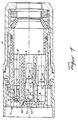
- a number of low-current plug sockets 4 and high-voltage plug sockets 5 and a protective conductor plug socket 6 are held in a plug housing 1 by means of a two-part holder 2, 3.
- the two parts 2 and 3 of the holder are axially interlocking and arranged, the holder part 2 forming the end face 7 of the mother plug part with axially directed receptacles 8 for the low-current plugs 4 and receptacles 9 for the high-current plugs 5 and receptacles 10 for the Protective conductor socket 6 is provided.
- the receptacles 8 to 10 each have a collar 11 at their end facing the end face 7 and at a uniform distance from the end face 7, but only the protective conductor plug socket 6 rests with its free end 12 on the collar 11 of the receptacle 10, while the remaining, current-carrying plug sockets 4 and 5 to form an air gap 13 end at a distance in front of the respective collar 11.
- the high-current plug sockets 5 and the protective conductor plug socket 6 are held by means of spring tongues 14 of the holder part 3 which are placed radially to their axis, the spring tongues 14 being forcibly parked inward when the two holder parts 2 and 3 are brought together via suitable inclined surfaces and each reach behind a collar 15 of the sockets 5 and 6.
- the low-current plug sockets 4 are supported on a collar 17 in the receptacles 8 by means of spring tongues 16 which are formed on them and are radially parked.
- the low-current plug sockets 4 and the high-current plug sockets 5 are each arranged in groups and arranged essentially on both sides of a parting plane 18 bisecting the outline of the mother connector part.
- One of the high-voltage sockets 5 is arranged as a central center contact 19, while the other sockets 4, 5 and 6 are arranged on a circular line concentric with the axis of the center contact.
- the heavy current plug sockets 5 are, as can be seen in particular in FIG.
- the sleeves 20 each having a cylindrical jacket-shaped section 21 and a collar 23 spanning the end edge 22 of the respective heavy current plug socket 5 and exclusively by means of the power socket 5 are held in the receptacles 9.
- the sleeves 20 encompass the shaft part of the high-voltage plug sockets 5 essentially over its entire length, while the collar 23 overlapping the string edge 22 of the plug sockets 5 has a thickness corresponding to the air gap 13, such that the collar 23 on the one hand abuts the collar 11 of the receptacles 9 and, on the other hand, the front edge 22. This ensures that a sufficient air gap 13 is ensured with respect to the high-voltage plug sockets 5 and the sleeves 20 also form a creepage distance extension, which allows the mother plug part to be manufactured and used in a small design.
Landscapes
- Connector Housings Or Holding Contact Members (AREA)
- Manufacturing Of Electrical Connectors (AREA)
- Details Of Connecting Devices For Male And Female Coupling (AREA)
Claims (7)
- Pièce de connexion femelle pour la réalisation simultanée de connexions de courants fort et faible, constituée d'un boîtier dans lequel sont logées un certain nombre de douilles de courant faible et de douilles de courant fort et au moins une douille de fil de protection, qui sont maintenues dans le boîtier grâce à des languettes élastiques, disposées sur l'une des parties d'un support en deux parties séparables axialement et engagé dans le boîtier, orientées raidalement vers la douille correspondante et s'engageant derrière ces dernières, où les douilles de courant faible (4) et les douilles de courant fort (5) sont disposées par groupes, où les trous récepteurs des douilles, ménagés dans le boîtier, sont tous de taille identique, et où seules les douilles de courant fort (5) sont recouvertes, au moins à leur extrémité frontale, par une douille (20) en matériau non conducteur, maintenue dans les trous récepteurs, afin de ménager un espace libre (13).
- Pièce de connexion femelle selon la revendication 1 caractérisée en ce que les groupes de douilles de courant fort (5) et de douilles de courant faible (4) sont disposés de part et d'autre d'un plan de séparation (18) divisant en deux la surface de projection horizontale du boîtier (1).
- Pièce de connexion femelle selon les revendications 1 et 2 caractérisée en ce que une des douilles de courant fort (5) est disposée au centre de la surface de projection horizontale du boîtier pour constituer un contact central (19) et en ce que les autres douilles (4), (5), (6) sont disposées sur un cercle concentrique autour de l'axe du contact central (19).
- Pièces de connexion femelle selon les revendications 1 à 3 caractérisée en ce que toutes les douilles de courant faible et de courant fort (4), (5) sont disposées à une distance identique de la surface frontale (7) de la pièce de connexion femelle et en ce que la douille du fil de protection (6) est disposée à une plus petite distance de ladite surface frontale que les douilles de courant fort ou de courant faible (4), (5) par définition conductrices.
- Pièce de connexion femelle selon les revendications 1 à 4 caractérisée en ce que les douilles (20) en matériau non conducteur comportent une partie cylindrique (21) entourant la tige des douilles de courant fort (5) et un épaulement (23) recouvrant le bord frontal libre (22) de la douille de courant fort (5).
- Pièce de connexion femelle selon les revendications 1 à 5 caractérisée en ce que l'épaulement (23) des douilles (20) en matériau non conducteur entourant les douilles de courant fort (5), remplissent approximativement l'espace entre le bord frontal libre (22) de la douille de courant fort (5) et le fond du trou récepteur correspondant (9).
- Pièce de connexion femelle selon les revendications 1 à 6 caractérisée en ce que les douilles (20) en matériau non conducteur sont maintenues dans les trous récepteurs dans le support (2), (3) par les douilles de courant fort (5) qui sont elles-mêmes maintenues dans le support par des languettes élastiques (14) s'engageant derrière le collet intérieur (15) des douilles (5), orientées radialement vers l'axe de ces dernières et se mettant obligatoirement en position inclinées lorsque les parties de support (2), (3) sont engagées l'une dans l'autre.
Applications Claiming Priority (2)
| Application Number | Priority Date | Filing Date | Title |
|---|---|---|---|
| DE3837697A DE3837697A1 (de) | 1988-11-07 | 1988-11-07 | Mutter-steckerteil zur gleichzeitigen herstellung von stark- und schwachstromsteckverbindungen |
| DE3837697 | 1988-11-07 |
Publications (3)
| Publication Number | Publication Date |
|---|---|
| EP0367903A2 EP0367903A2 (fr) | 1990-05-16 |
| EP0367903A3 EP0367903A3 (en) | 1990-11-28 |
| EP0367903B1 true EP0367903B1 (fr) | 1993-03-24 |
Family
ID=6366632
Family Applications (1)
| Application Number | Title | Priority Date | Filing Date |
|---|---|---|---|
| EP89112151A Expired - Lifetime EP0367903B1 (fr) | 1988-11-07 | 1989-07-04 | Pièce de connexion femelle pour la réalisation simultanée de connexions à basse et haute intensité |
Country Status (2)
| Country | Link |
|---|---|
| EP (1) | EP0367903B1 (fr) |
| DE (2) | DE3837697A1 (fr) |
Cited By (2)
| Publication number | Priority date | Publication date | Assignee | Title |
|---|---|---|---|---|
| US6234842B1 (en) | 1998-11-20 | 2001-05-22 | Vlt Corporation | Power converter connector assembly |
| DE10118186C1 (de) * | 2001-04-11 | 2002-06-13 | Siemens Ag | Kontaktstück für eine elektrische Steckverbindung |
Families Citing this family (7)
| Publication number | Priority date | Publication date | Assignee | Title |
|---|---|---|---|---|
| US5997367A (en) * | 1995-06-05 | 1999-12-07 | Vlt Corporation | Adapter |
| EP0840400A3 (fr) * | 1996-11-05 | 1999-06-30 | Vlt Corporation | Contact à douille |
| CN1210380A (zh) * | 1997-08-28 | 1999-03-10 | 徐晓鹰 | 三相电力电缆插接式接头 |
| DE19941509A1 (de) * | 1999-08-31 | 2001-03-29 | Interconnectron Ges Fuer Ind S | Rundsteckverbinder zur Herstellung elektrischer Leitungsverbindungen |
| DE102004006707A1 (de) * | 2004-02-11 | 2005-09-01 | Rexroth Indramat Gmbh | Sicherheitssteckverbinder |
| CN112670739A (zh) * | 2020-12-28 | 2021-04-16 | 深圳市易二三科技有限公司 | 一种新型隐藏式温控连接器 |
| DE102024106917A1 (de) * | 2024-03-11 | 2025-09-11 | WAGO Verwaltungsgesellschaft mit beschränkter Haftung | Leiteranschlussklemme und Verfahren zur Montage einer Leiteranschlussklemme |
Family Cites Families (8)
| Publication number | Priority date | Publication date | Assignee | Title |
|---|---|---|---|---|
| US3794958A (en) * | 1972-06-19 | 1974-02-26 | Amp Inc | High voltage connector |
| US3850495A (en) * | 1973-06-06 | 1974-11-26 | Amp Inc | Multi-pin shielded high voltage connector |
| FR2400783A1 (fr) * | 1977-08-16 | 1979-03-16 | Simeone Jean Pierre | Prise jumelee pour alimentation electrique et television |
| DE2811774A1 (de) * | 1978-03-17 | 1979-09-20 | Bunker Ramo | Elektrischer buchsenkontakt |
| DE3041337A1 (de) * | 1980-11-03 | 1982-09-09 | Felten & Guilleaume Energietechnik GmbH, 5000 Köln | Steckverbindungs-kupplung fuer elektrische hochspannungsleitungen |
| GB2137027B (en) * | 1983-03-14 | 1986-03-19 | Itt | Contact retention assembly |
| DE3611661C1 (de) * | 1986-04-07 | 1987-06-11 | Harting Elektronik Gmbh | Elektrische Steckverbindung |
| DE3625865A1 (de) * | 1986-07-31 | 1988-02-04 | Siemens Ag | Steckverbinder mit leistenfoermigen isolierstoffkoerpern |
-
1988
- 1988-11-07 DE DE3837697A patent/DE3837697A1/de not_active Withdrawn
-
1989
- 1989-07-04 EP EP89112151A patent/EP0367903B1/fr not_active Expired - Lifetime
- 1989-07-04 DE DE8989112151T patent/DE58903882D1/de not_active Expired - Fee Related
Cited By (2)
| Publication number | Priority date | Publication date | Assignee | Title |
|---|---|---|---|---|
| US6234842B1 (en) | 1998-11-20 | 2001-05-22 | Vlt Corporation | Power converter connector assembly |
| DE10118186C1 (de) * | 2001-04-11 | 2002-06-13 | Siemens Ag | Kontaktstück für eine elektrische Steckverbindung |
Also Published As
| Publication number | Publication date |
|---|---|
| EP0367903A2 (fr) | 1990-05-16 |
| DE58903882D1 (de) | 1993-04-29 |
| EP0367903A3 (en) | 1990-11-28 |
| DE3837697A1 (de) | 1990-05-10 |
Similar Documents
| Publication | Publication Date | Title |
|---|---|---|
| DE68908731T2 (de) | Mikrokoaxiale Verbinderfamilie. | |
| DE69021029T2 (de) | Kreisförmiger elektrischer DIN-Verbinder. | |
| DE3587104T2 (de) | Elektrische steckervorrichtung. | |
| DE202018100111U1 (de) | Modulverbinder | |
| DE1615001B2 (de) | Elektrische steckvorrichtung | |
| EP0367903B1 (fr) | Pièce de connexion femelle pour la réalisation simultanée de connexions à basse et haute intensité | |
| DE10035611A1 (de) | Mechanischer Verbinder für elektrische Anschlüsse | |
| EP0447660B1 (fr) | Dispositif de connexion pour câbles de transmission de données, en particulier pour un réseau de données | |
| DE10033800A1 (de) | Stiftartige Zündspulenbaugruppe | |
| EP2515388A1 (fr) | Dispositif de chauffage électrique | |
| EP0444478A1 (fr) | Porte-contact pour prise de courant ou connecteur pour le raccordement de remorques de véhicules | |
| DE29718003U1 (de) | Elektrische Verbindungseinrichtung | |
| DE3688596T2 (de) | Hochspannungsanschlussvorrichtung, insbesondere für Hochspannungstransformator. | |
| DE29804728U1 (de) | Steckverbinder zur gemeinsamen Herstellung von Leistungsstrom und Steuerstromverbindungen | |
| DE69612936T2 (de) | Steckdosenbox | |
| DE1615655A1 (de) | Elektrisches Steckergehaeuse | |
| DE19635260A1 (de) | Elektrische Mehrpol-Kontaktbuchse | |
| DE4338705C2 (de) | Verbindungsstück für Stromschienen | |
| EP0254226B1 (fr) | Combinaison de fiche et de prise pour la connexion de lampes et d'appareils électriques | |
| DE4135391C1 (en) | Cable connector for medium high voltage and high current - has socket with cup-shaped contact element, and cylindrical insulating housing covering inserted cable | |
| DE19844414A1 (de) | Elektrische Verbinderanordnung mit Zusatzverriegelungseinrichtung | |
| DE3732576A1 (de) | Explosionsgeschuetzte und/oder schlagwettergeschuetzte steckdurchfuehrung | |
| DE3119218A1 (de) | Mehrpolige steckverbindung | |
| DE3302924C3 (de) | Elektrische Steckverbindung | |
| DE3507875A1 (de) | Koaxiale elektrische steckverbindung |
Legal Events
| Date | Code | Title | Description |
|---|---|---|---|
| PUAI | Public reference made under article 153(3) epc to a published international application that has entered the european phase |
Free format text: ORIGINAL CODE: 0009012 |
|
| AK | Designated contracting states |
Kind code of ref document: A2 Designated state(s): CH DE FR GB IT LI |
|
| PUAL | Search report despatched |
Free format text: ORIGINAL CODE: 0009013 |
|
| AK | Designated contracting states |
Kind code of ref document: A3 Designated state(s): CH DE FR GB IT LI |
|
| RHK1 | Main classification (correction) |
Ipc: H01R 13/53 |
|
| 17P | Request for examination filed |
Effective date: 19901127 |
|
| 17Q | First examination report despatched |
Effective date: 19920828 |
|
| GRAA | (expected) grant |
Free format text: ORIGINAL CODE: 0009210 |
|
| AK | Designated contracting states |
Kind code of ref document: B1 Designated state(s): CH DE FR GB IT LI |
|
| REF | Corresponds to: |
Ref document number: 58903882 Country of ref document: DE Date of ref document: 19930429 |
|
| GBT | Gb: translation of ep patent filed (gb section 77(6)(a)/1977) |
Effective date: 19930413 |
|
| ET | Fr: translation filed | ||
| ITF | It: translation for a ep patent filed | ||
| PLBE | No opposition filed within time limit |
Free format text: ORIGINAL CODE: 0009261 |
|
| STAA | Information on the status of an ep patent application or granted ep patent |
Free format text: STATUS: NO OPPOSITION FILED WITHIN TIME LIMIT |
|
| 26N | No opposition filed | ||
| PGFP | Annual fee paid to national office [announced via postgrant information from national office to epo] |
Ref country code: DE Payment date: 19970625 Year of fee payment: 9 |
|
| PG25 | Lapsed in a contracting state [announced via postgrant information from national office to epo] |
Ref country code: DE Free format text: LAPSE BECAUSE OF NON-PAYMENT OF DUE FEES Effective date: 19990501 |
|
| PGFP | Annual fee paid to national office [announced via postgrant information from national office to epo] |
Ref country code: GB Payment date: 19990517 Year of fee payment: 11 |
|
| PGFP | Annual fee paid to national office [announced via postgrant information from national office to epo] |
Ref country code: CH Payment date: 19990709 Year of fee payment: 11 |
|
| PGFP | Annual fee paid to national office [announced via postgrant information from national office to epo] |
Ref country code: FR Payment date: 19990720 Year of fee payment: 11 |
|
| PG25 | Lapsed in a contracting state [announced via postgrant information from national office to epo] |
Ref country code: GB Free format text: LAPSE BECAUSE OF NON-PAYMENT OF DUE FEES Effective date: 20000704 |
|
| PG25 | Lapsed in a contracting state [announced via postgrant information from national office to epo] |
Ref country code: LI Free format text: LAPSE BECAUSE OF NON-PAYMENT OF DUE FEES Effective date: 20000731 Ref country code: CH Free format text: LAPSE BECAUSE OF NON-PAYMENT OF DUE FEES Effective date: 20000731 |
|
| GBPC | Gb: european patent ceased through non-payment of renewal fee |
Effective date: 20000704 |
|
| REG | Reference to a national code |
Ref country code: CH Ref legal event code: PL |
|
| PG25 | Lapsed in a contracting state [announced via postgrant information from national office to epo] |
Ref country code: FR Free format text: LAPSE BECAUSE OF NON-PAYMENT OF DUE FEES Effective date: 20010330 |
|
| REG | Reference to a national code |
Ref country code: FR Ref legal event code: ST |
|
| PG25 | Lapsed in a contracting state [announced via postgrant information from national office to epo] |
Ref country code: IT Free format text: LAPSE BECAUSE OF NON-PAYMENT OF DUE FEES;WARNING: LAPSES OF ITALIAN PATENTS WITH EFFECTIVE DATE BEFORE 2007 MAY HAVE OCCURRED AT ANY TIME BEFORE 2007. THE CORRECT EFFECTIVE DATE MAY BE DIFFERENT FROM THE ONE RECORDED. Effective date: 20050704 |