EP0367925A2 - Dispositif de codage et de décodage de signaux de television couleur en standard PAL et méthode de transmission de signaux de television couleur en standard PAL - Google Patents
Dispositif de codage et de décodage de signaux de television couleur en standard PAL et méthode de transmission de signaux de television couleur en standard PAL Download PDFInfo
- Publication number
- EP0367925A2 EP0367925A2 EP89115758A EP89115758A EP0367925A2 EP 0367925 A2 EP0367925 A2 EP 0367925A2 EP 89115758 A EP89115758 A EP 89115758A EP 89115758 A EP89115758 A EP 89115758A EP 0367925 A2 EP0367925 A2 EP 0367925A2
- Authority
- EP
- European Patent Office
- Prior art keywords
- pal
- color difference
- circuit
- luminance
- difference signals
- Prior art date
- Legal status (The legal status is an assumption and is not a legal conclusion. Google has not performed a legal analysis and makes no representation as to the accuracy of the status listed.)
- Withdrawn
Links
- 238000000034 method Methods 0.000 title claims description 5
- 238000001914 filtration Methods 0.000 claims abstract description 16
- 230000005540 biological transmission Effects 0.000 claims description 9
- 239000011159 matrix material Substances 0.000 claims description 2
- 238000001228 spectrum Methods 0.000 description 7
- 230000000694 effects Effects 0.000 description 6
- 230000002123 temporal effect Effects 0.000 description 3
- 230000002238 attenuated effect Effects 0.000 description 1
- 238000000926 separation method Methods 0.000 description 1
- 230000008054 signal transmission Effects 0.000 description 1
Images




Classifications
-
- H—ELECTRICITY
- H04—ELECTRIC COMMUNICATION TECHNIQUE
- H04N—PICTORIAL COMMUNICATION, e.g. TELEVISION
- H04N9/00—Details of colour television systems
- H04N9/64—Circuits for processing colour signals
- H04N9/646—Circuits for processing colour signals for image enhancement, e.g. vertical detail restoration, cross-colour elimination, contour correction, chrominance trapping filters
-
- H—ELECTRICITY
- H04—ELECTRIC COMMUNICATION TECHNIQUE
- H04N—PICTORIAL COMMUNICATION, e.g. TELEVISION
- H04N11/00—Colour television systems
- H04N11/06—Transmission systems characterised by the manner in which the individual colour picture signal components are combined
- H04N11/12—Transmission systems characterised by the manner in which the individual colour picture signal components are combined using simultaneous signals only
- H04N11/14—Transmission systems characterised by the manner in which the individual colour picture signal components are combined using simultaneous signals only in which one signal, modulated in phase and amplitude, conveys colour information and a second signal conveys brightness information, e.g. NTSC-system
- H04N11/16—Transmission systems characterised by the manner in which the individual colour picture signal components are combined using simultaneous signals only in which one signal, modulated in phase and amplitude, conveys colour information and a second signal conveys brightness information, e.g. NTSC-system the chrominance signal alternating in phase, e.g. PAL-system
Definitions
- the invention relates to a device for coding color television signals according to the PAL standard and a device for decoding color television signals according to the PAL standard.
- the invention further relates to methods for transmitting color television signals according to the PAL standard.
- a device with the features specified in the preamble of claim 1 is known from the unpublished German patent application with the file number P 38 07 248.3.
- three-dimensional filtering is carried out in the luminance channel and in the chrominance channel in such a way that both the luminance and the chrominance components in the three-dimensional frequency space are uniquely assigned, so that No interference in the form of "cross-color” and "cross-luminance” occur at the receiving end.
- the PAL coding or PAL decoding is carried out - as is generally the case - by means of quadrature modulation or quadrature demodulation.
- the three-dimensional band limitation of the luminance component leads to a loss of luminance bandwidth.
- the invention has for its object to develop a device of the type specified in the preamble of claim 1 such that the loss of luminance bandwidth is reduced.
- the advantages of the invention consist essentially in the fact that the usable luminance bandwidth is increased compared to the known circuit.
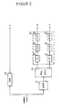
- FIG. 1 shows an embodiment for a device for coding color television signals according to the PAL standard.
- RGB signals generated in a television camera are present at the entrance of the device.
- a luminance signal Y, a first color difference signal U and a second color difference signal V are generated from these in a matrix circuit 1.
- the luminance signal Y is fed to a three-dimensional filter circuit 2 arranged in the luminance channel.
- the three-dimensionally filtered luminance signal is fed to an input of an addition circuit 14.
- the color difference signals U and V are fed to a three-dimensional filter circuit 3.
- the color difference signal U passes through a horizontal low-pass filter 4, a vertical low-pass filter 5 and a combined vertical-time filter 6.
- the color difference signal V passes through a horizontal low-pass filter 7, a vertical low-pass filter 8 and a combined vertical-time filter 9.
- the color difference signals are band-limited in the horizontal direction at 1.3 MHz.
- the color difference signals are band-limited in the vertical direction at 78 c / ph.
- this band limitation in the vertical direction is necessary in order to enable the two color difference signals to be separated from one another at the receiving end.
- Filters 4 and 5 or 7 and 8 can alternatively to that in The cascading of two one-dimensional filters shown in the figure can also be implemented as a general multi-dimensional filter (planar filter).
- the color difference signals in the f y , f t plane are band-limited.
- the color difference signals filtered three-dimensionally in the manner described above are fed to a conventional PAL modulator 10 and converted there into a modulated chrominance signal in a basically known manner.
- the modulated chrominance signal is then fed to a circuit 11 for three-dimensional residual sideband filtering, which consists of a residual sideband filter 12 and an amplifier 13 whose gain factor is 2.
- the output signal of the amplifier 13 reaches a second input of the adder circuit 14, at the output of which a coded color television signal is consequently available.
- FIG. 3 shows a chrominance spectrum in the f x , f y plane at the output of the PAL modulator 10. Due to the line-alternating switching of the color difference signal V, the spectra of U and V are mutually offset in the direction of vertical frequencies and are reversed in the direction of horizontal frequencies the color auxiliary carrier f sc or -f sc arranged. The spectra of U and V are not overlapping in the vertical direction because of the vertical low-pass filters 5, 8.
- the color difference signals according to a feature of the invention in the vertical low-pass filters 5 and 8 are band limited to 78 c / ph.
- the effect of these filters can be seen from FIG. 3, as already explained above.
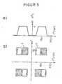
- the signal at the output of the residual sideband filter can be seen in FIG. 5b.
- the residual sideband filtering in the spectrum of the color difference signals in the range between -78 c / ph and 78 c / ph creates free space which can be used for the transmission of luminance information.
- FIG. 5a shows the amount of the transfer function of the residual sideband filter in the direction of vertical frequencies. It can be seen that the residual sideband filter is only permeable in the range between 78 and 234 c / ph and between -234 and -78 c / ph. The Nyquist flanks of the residual sideband filter occur at ⁇ 78 and ⁇ 234 c / ph.
- FIG. 4 illustrates the effect of the residual sideband filter 12 in the direction of horizontal frequencies. It can be seen that only the frequency range above the color subcarrier f sc is occupied with chrominance information. The Nyquist flank occurs at ⁇ f sc . The frequency range below the color subcarrier is thus available for the transmission of luminance information.
- FIG. 6a shows the amount of the transfer function of the residual sideband filter 12 as a function of the temporal frequencies f t . The Nyquist flanks occur at ⁇ 6.25 and ⁇ 18.75 Hz.
- FIG. 2 shows an exemplary embodiment of a device for decoding color television signals.
- the color television signal transmitted via the transmission channel is present at the input. This is supplied on the one hand to a three-dimensional filter circuit 20 and on the other hand to a three-dimensional bandpass filter 21.
- the horizontally high-frequency luminance signal components are essentially subjected to vertical-time filtering for "cross-luminance" reduction.
- the luminance signal Y is available at the output of the three-dimensional filter circuit 20.
- the chrominance signal components are separated from the luminance signal components and fed to a conventional PAL demodulator 22.
- the output signals of the PAL demodulator 22 are a three-dimensional filter circuit 23 fed.
- the color difference signal U passes through a combined vertical-time filter 24, a vertical low-pass filter 25 and a horizontal low-pass filter 26.
- the color difference signal V passes through a combined vertical-time filter 27, a vertical low-pass filter 28 and a horizontal low-pass filter 29.
- the vertical-time filters 24 and 27 serve to reduce "cross-color" interference.
- the vertical low-pass filters 25 and 28 effect a vertical band limitation of the color difference signals to 78 c / ph and are necessary because of the use of the residual sideband transmission for the error-free separation of the two color difference signals from one another.
- the horizontal low-pass filters 26 and 29 the color difference signals are limited in the direction of horizontal frequencies at 0.7 MHz.
- both a color television receiver with a conventional color decoder and a color television receiver with a decoder according to the invention can be used to receive a color television signal encoded with a coder according to the invention.
Landscapes
- Engineering & Computer Science (AREA)
- Multimedia (AREA)
- Signal Processing (AREA)
- Color Television Systems (AREA)
Applications Claiming Priority (2)
| Application Number | Priority Date | Filing Date | Title |
|---|---|---|---|
| DE3838122 | 1988-11-10 | ||
| DE19883838122 DE3838122A1 (de) | 1988-11-10 | 1988-11-10 | Einrichtung zur codierung und decodierung von farbfernsehsignalen nach dem pal-standard und verfahren zur uebertragung von farbfernsehsignalen nach dem pal-standard |
Publications (2)
| Publication Number | Publication Date |
|---|---|
| EP0367925A2 true EP0367925A2 (fr) | 1990-05-16 |
| EP0367925A3 EP0367925A3 (fr) | 1991-10-02 |
Family
ID=6366878
Family Applications (1)
| Application Number | Title | Priority Date | Filing Date |
|---|---|---|---|
| EP19890115758 Withdrawn EP0367925A3 (fr) | 1988-11-10 | 1989-08-26 | Dispositif de codage et de décodage de signaux de television couleur en standard PAL et méthode de transmission de signaux de television couleur en standard PAL |
Country Status (2)
| Country | Link |
|---|---|
| EP (1) | EP0367925A3 (fr) |
| DE (1) | DE3838122A1 (fr) |
Cited By (1)
| Publication number | Priority date | Publication date | Assignee | Title |
|---|---|---|---|---|
| US5255081A (en) * | 1991-02-25 | 1993-10-19 | Sony Corporation | Color television camera apparatus and method for producing an analog video signal for use with a plurality of video standard system |
Family Cites Families (1)
| Publication number | Priority date | Publication date | Assignee | Title |
|---|---|---|---|---|
| US4683490A (en) * | 1985-06-05 | 1987-07-28 | Rca Corporation | Video signal processing apparatus |
-
1988
- 1988-11-10 DE DE19883838122 patent/DE3838122A1/de not_active Withdrawn
-
1989
- 1989-08-26 EP EP19890115758 patent/EP0367925A3/fr not_active Withdrawn
Cited By (1)
| Publication number | Priority date | Publication date | Assignee | Title |
|---|---|---|---|---|
| US5255081A (en) * | 1991-02-25 | 1993-10-19 | Sony Corporation | Color television camera apparatus and method for producing an analog video signal for use with a plurality of video standard system |
Also Published As
| Publication number | Publication date |
|---|---|
| DE3838122A1 (de) | 1990-05-17 |
| EP0367925A3 (fr) | 1991-10-02 |
Similar Documents
| Publication | Publication Date | Title |
|---|---|---|
| DD292352A5 (de) | Anordnung zum empfangen eines fernsehsignals | |
| DE3435264C2 (fr) | ||
| DD295480A5 (de) | Einrichtung zum ergaenzen eines fernsehsignals | |
| EP0090236A2 (fr) | Système pour la transmission numérique de signaux d'images de télévision à redondance réduite | |
| DE2810697A1 (de) | Verfahren zur trennung des farbartsignals vom leuchtdichtesignal bei farbfernsehsignalen mit quadraturmodulierten farbhilfstraegern | |
| WO1990013210A1 (fr) | Systeme de television couleur comportant des dispositifs pour le codage et le decodage de signaux de television couleur | |
| DE3786581T2 (de) | Kodierung und dekodierung von digitalen videokomponentensignalen. | |
| DE2533446C2 (de) | Nach dem SECAM-Verfahren arbeitender Farbfernsehempfänger | |
| DE2319820A1 (de) | Farbcodiersystem | |
| EP0331985A2 (fr) | Méthode et dispositifs de codage et de décodage de signaux de télévision couleur | |
| EP0030700B1 (fr) | Dispositif pour la correction d'un signal non modulé à large bande, en particulier d'un signal vidéo de couleur, dans un système d'enregistrement et de reproduction de signaux | |
| DE2106437A1 (de) | Einrichtung zum Erzeugen von Färb Signalen | |
| DE69205224T2 (de) | Filter mit flachen flanken zum zusammensetzen und trennen von weston-clean-pal-signalen. | |
| DE3838122A1 (de) | Einrichtung zur codierung und decodierung von farbfernsehsignalen nach dem pal-standard und verfahren zur uebertragung von farbfernsehsignalen nach dem pal-standard | |
| EP0432529A2 (fr) | Méthode de transmissions de signaux vidéo grand écran pour leur affichage sur des récepteurs de télévision à format d'image conventionnel ou agrandi | |
| DE2628816C3 (fr) | ||
| DE3528699A1 (de) | Decodierung von digitalen pal-videosignalen | |
| EP0425799B1 (fr) | Dispositif de codage de signaux de télévision couleur | |
| DE3901117C1 (en) | Compatible frequency-division multiplex television system | |
| DE2533445C2 (de) | Farbfernsehübertragungssystem | |
| DE1196696B (de) | Farbfernsehverfahren sowie Farbfernsehsender und Farbfernsehempfaenger zur Anwendungbei diesem Verfahren | |
| CH643976A5 (de) | Verfahren zum aufmodulieren eines zusammengesetzten farbfernsehsignals auf ein traegersignal und vorrichtungen zum durchfuehren dieses verfahrens. | |
| DE3415956A1 (de) | Verfahren zur speicherung frequenzmodulierter signale und schaltungsanordnung hierfuer | |
| DE3941576C1 (fr) | ||
| DE68926004T2 (de) | Übersprechstörung für übertragene Signale und Demodulation von Restseitenbandsignalen |
Legal Events
| Date | Code | Title | Description |
|---|---|---|---|
| PUAI | Public reference made under article 153(3) epc to a published international application that has entered the european phase |
Free format text: ORIGINAL CODE: 0009012 |
|
| AK | Designated contracting states |
Kind code of ref document: A2 Designated state(s): AT DE FR GB IT |
|
| PUAL | Search report despatched |
Free format text: ORIGINAL CODE: 0009013 |
|
| AK | Designated contracting states |
Kind code of ref document: A3 Designated state(s): AT DE FR GB IT |
|
| STAA | Information on the status of an ep patent application or granted ep patent |
Free format text: STATUS: THE APPLICATION IS DEEMED TO BE WITHDRAWN |
|
| 18D | Application deemed to be withdrawn |
Effective date: 19920523 |