EP0367955B1 - Joint à lèvres pour l'étanchéité dans un carter en plusieurs parties - Google Patents
Joint à lèvres pour l'étanchéité dans un carter en plusieurs parties Download PDFInfo
- Publication number
- EP0367955B1 EP0367955B1 EP89117468A EP89117468A EP0367955B1 EP 0367955 B1 EP0367955 B1 EP 0367955B1 EP 89117468 A EP89117468 A EP 89117468A EP 89117468 A EP89117468 A EP 89117468A EP 0367955 B1 EP0367955 B1 EP 0367955B1
- Authority
- EP
- European Patent Office
- Prior art keywords
- diameter
- sealing ring
- shaft sealing
- housing
- seat surface
- Prior art date
- Legal status (The legal status is an assumption and is not a legal conclusion. Google has not performed a legal analysis and makes no representation as to the accuracy of the status listed.)
- Expired - Lifetime
Links
- 238000007789 sealing Methods 0.000 title claims abstract description 72
- 230000007704 transition Effects 0.000 claims abstract description 12
- 229920001971 elastomer Polymers 0.000 claims description 7
- 239000000806 elastomer Substances 0.000 claims description 7
- 239000002184 metal Substances 0.000 claims 1
- 238000004073 vulcanization Methods 0.000 claims 1
- 230000003068 static effect Effects 0.000 abstract description 6
- 230000002411 adverse Effects 0.000 abstract description 2
- 230000000694 effects Effects 0.000 abstract description 2
- 239000011248 coating agent Substances 0.000 description 2
- 238000000576 coating method Methods 0.000 description 2
- 238000004519 manufacturing process Methods 0.000 description 2
- 239000003566 sealing material Substances 0.000 description 2
- 230000001419 dependent effect Effects 0.000 description 1
- 238000005516 engineering process Methods 0.000 description 1
- 238000009434 installation Methods 0.000 description 1
- 239000004922 lacquer Substances 0.000 description 1
- 230000000284 resting effect Effects 0.000 description 1
Images
Classifications
-
- F—MECHANICAL ENGINEERING; LIGHTING; HEATING; WEAPONS; BLASTING
- F16—ENGINEERING ELEMENTS AND UNITS; GENERAL MEASURES FOR PRODUCING AND MAINTAINING EFFECTIVE FUNCTIONING OF MACHINES OR INSTALLATIONS; THERMAL INSULATION IN GENERAL
- F16J—PISTONS; CYLINDERS; SEALINGS
- F16J15/00—Sealings
- F16J15/16—Sealings between relatively-moving surfaces
- F16J15/32—Sealings between relatively-moving surfaces with elastic sealings, e.g. O-rings
- F16J15/3268—Mounting of sealing rings
- F16J15/3276—Mounting of sealing rings with additional static sealing between the sealing, or its casing or support, and the surface on which it is mounted
-
- F—MECHANICAL ENGINEERING; LIGHTING; HEATING; WEAPONS; BLASTING
- F16—ENGINEERING ELEMENTS AND UNITS; GENERAL MEASURES FOR PRODUCING AND MAINTAINING EFFECTIVE FUNCTIONING OF MACHINES OR INSTALLATIONS; THERMAL INSULATION IN GENERAL
- F16J—PISTONS; CYLINDERS; SEALINGS
- F16J15/00—Sealings
- F16J15/16—Sealings between relatively-moving surfaces
- F16J15/32—Sealings between relatively-moving surfaces with elastic sealings, e.g. O-rings
- F16J15/3248—Sealings between relatively-moving surfaces with elastic sealings, e.g. O-rings provided with casings or supports
- F16J15/3252—Sealings between relatively-moving surfaces with elastic sealings, e.g. O-rings provided with casings or supports with rigid casings or supports
Definitions
- the invention relates to an elastomeric shaft sealing ring for sealing rotating shafts in a divided receiving machine housing, consisting of a metallic housing ring with an approximately rectangular cross section, on the radial leg of which the elastomeric sealing lip lying radially on the shaft with its inner circumference is vulcanized, and the axial leg of which is on the outer periphery an elastomer is coated, which forms the seating surface when the shaft sealing ring is pressed into the divided machine housing, and which has at least two annular circumferential areas (8, 9) of different diameters on the outer circumference (US Pat. No. 4,026,563).
- Metallic housing rings of shaft sealing rings for sealing rotating shafts have an approximately rectangular cross section, and they are vulcanized into the elastomer body of the shaft sealing ring or vulcanized onto the outer surfaces. Due to manufacturing technology, an arch-shaped transition area with a small transition radius unavoidably arises in the transition area between the axial leg and the radial leg of the housing ring.
- the radial limb of the housing ring is then connected on the inner circumference to the elastomeric sealing lip resting on the shaft, while the axial limb with its outer lateral surface forms the static seal and the seating surface for pressing the shaft sealing ring into the receiving machine housing with a press fit.
- the casing surface is provided with an elastomer layer, which either consists of the elastomer of the shaft sealing ring itself, or is formed by applying the elastomer as a sealing lacquer, for example.
- the elastomer layer preferably has a sealing profile with an approximately comb-like or undulating contour in cross section.
- the outer diameter of the shaft sealing ring is somewhat larger than the inner diameter of the receiving machine housing.
- the press fit conditions and thus the radial force acting between the mounting hole and seat is thus determined from the resulting overlap from the tolerances of the mounting hole and the press fit allowance.
- the required values for the interference fit of the shaft sealing ring are determined depending on the diameter, and for shaft sealing rings of usual diameter they are approximately in the range of tenths of a millimeter.
- the elastomeric outer surface of a shaft sealing ring has two areas of different diameters, the area with the larger diameter being arranged on the assembly side.
- the machine housing receiving the shaft sealing ring is often divided in the axial direction.
- the receiving machine housing opens when the shaft sealing ring is pressed in with high pressure in its parting planes or when the shaft sealing ring is thermally expanded at operating temperature, there are axial gaps with sealing problems in the machine housing and the seat of the shaft sealing ring in the machine housing becomes relaxed.
- the shaft sealing ring has radially outwardly projecting elastomeric projections in the area of the machine housing division planes. Although these seal the gaps of the housing formed during expansion, they do not prevent the machine housing from expanding when the shaft sealing ring is pressed in, with the disadvantageous consequences of a loosened press fit.
- the shaft sealing ring is divided even in the parting planes of the machine housing to be accommodated. In this case, however, the sealing lip itself is also divided and there are only difficult to control sealing problems on the shaft to be sealed.
- the present invention is therefore based on the object to provide a shaft sealing ring according to the preamble of the main patent claim, which can also be used in a split accommodating machine housing without the disadvantages described with a sufficient press fit with good static sealing.
- the production of the shaft sealing ring should not be significantly more complex than conventional shaft sealing rings.
- this object is achieved by a shaft sealing ring, the axial limb of which widens conically towards the end face of the axial limb, its change in diameter being approximately equal to the difference in diameter between the two seat surface regions, and its housing ring cross-section in the transition region between the axial limb and radial limb is designed to have a curve with the largest possible transition radius.
- the seat surface on the outer circumference of the shaft sealing ring preferably has two annular circumferential regions of different diameters, the circumferential region of the larger diameter being on the assembly-side end face of the seat surface which forms the press-in side of the shaft sealing ring when pressed into the housing.
- the size of its diameter is approximately equal to the prescribed value.
- the circumferential seat area with the smaller diameter lies on the bottom side of the shaft sealing ring facing away from the mounting side and is at most about 0.1 to 0.2 mm smaller than the prescribed minimum value for the press fit.
- the total maximum pressure acting on the receiving housing is reduced, and even with increased press-in forces, the pressing apart of the receiving divided machine housing is made more difficult. It was also found that the circumferential area with a larger diameter needs to be about a quarter to a half as large as the entire width of the end face.
- the dimensions of the shaft sealing ring according to the invention are primarily dependent on the sealing material used, the ring diameter and the installation situation. Deviations in diameter of the end face of the shaft sealing ring or its press fit allowances as well as the taper of the housing ring and the transition radius of curvature of the housing ring must be determined in accordance with the application.
- the invention thus provides a shaft sealing ring which can be used in the divided receiving machine housing without adverse consequences.
- the shaft sealing ring according to the invention can be pressed into divided receptacle housings without the receptacle housing expanding with gaps in the parting planes. Sealing problems on an axial gap formed and loosening of the press fit do not arise even in the case of thermal expansion at operating temperature.
- the shaft sealing ring according to the invention can also be produced with approximately the same outlay as conventional shaft sealing rings and can therefore also be used economically.
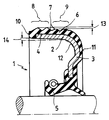
- the invention is represented by a cross-sectional image of a shaft sealing ring according to the invention.
- the shaft sealing ring 1 consists of a metallic housing ring 2 with a radial arm 3 and an axial arm 4, which is vulcanized onto the inner surface of an elastomeric sealing ring.
- the radial leg 3 is connected on the inner circumference to the elastomeric sealing lip 5 of the shaft sealing ring, and the outer circumferential surface of the axial leg 4 has a coating 6 made of the elastomeric sealing material, the outer surface of which is provided with a comb-like sealing profile 7 and which seals the seating surface of the shaft sealing ring 1 Pressing into the receiving machine housing (not shown) with a press fit.
- the outer lateral surface of the coating 6 has two annular circumferential areas 8, 9 of different diameters 13, the area 8 lying on the end face 10 on the assembly side having a larger diameter than the area 9 lying on the bottom side 11.
- the axial leg 4 of the metallic housing ring 2 widens conically 14 toward the end face side 10.
- the radially higher annular circumferential area 8 on the front 10 assembly side has a diameter that is within the allowable tolerances the prescribed diameter of the lateral surface to achieve the required press fit when pressed into the receiving housing, not shown.
- the seat area 9 of the bottom side 11 has a diameter which is about 0.1 to 0.2 mm smaller than the prescribed diameter for achieving the required press fit in the receiving machine housing but larger than the inside diameter of the receiving machine housing.
- the seating area 8 which encircles the end face in a ring shape, provides the required press fit in the receiving machine housing, in the bottom seating area area 9 which is encircling the bottom ring, only the comb profile 7 is elastically deformed, so that in this area 9, with a good static sealing effect, no press fit occurs .
- the pressure acting when inserting the shaft sealing ring 1 into the housing is thus reduced, so that in the case of a divided accommodating housing there is no pressing apart with disadvantageous consequences for the sealing and the seating of the shaft sealing ring 1.
- the conical extension 14 on the end face 10 compared to the bottom side 11 is approximately equal to the difference in the diameter of the two annular seat surfaces 8, 9, the radial seat surface pressing force is transmitted to the front end 10.
Landscapes
- Engineering & Computer Science (AREA)
- General Engineering & Computer Science (AREA)
- Mechanical Engineering (AREA)
- Sealing With Elastic Sealing Lips (AREA)
- Sealing Devices (AREA)
- Mechanical Sealing (AREA)
Claims (4)
- Joint d'arbre élastomère (1) pour l'étanchéité d'arbres rotatifs dans un carter de machine récepteur en plusieurs parties, consistant en un carter annulaire (2) métallique avec une section sensiblement en angle droit, sur la branche radiale (3) duquel la lèvre d'étanchéité (6) élastomère est vulcanisée avec sa périphérie interne reposant radialement sur l'arbre, et dont la branche axiale (4) est recouverte à sa periphérie externe avec un élastomère, qui forme la surface d'appui (6) lors de l'insertion du joint d'arbre (1) dans le carter de machine en plusieurs parties et qui présente à sa périphérie externe au moins deux zones (8,9) annulaires périphériques de diamètre différent, caractérisé en ce que la branche axiale (4) du carter annulaire (2) s'élargit vers le côté frontal (10) de la branche axiale (4), d'où il résulte que sa variation de diamètre (14) vers le côté frontal (10) est sensiblement égale à la différence de diamètre (13) des deux zones (8,9) de sruface d'appui, et que la section du carter annulaire (2) dans la zone de transition (12) entre la branche axiale (4) et la branche radiale (3) est formée avec un rayon de transition aussi grand que possible d'allure en forme de courbe.
- Joint d'arbre selon la revendication 1, caractérisé en ce que la zone (8) de surface d'appui annulaire périphérique avec le plus grand diamètre présente un diamètre qui est égal au diamètre prescrit pour l'obtention de l'ajustage serré requis dans le carter dans les limites des tolérances admises, en ce que le diamètre de la seconde zone (9) de surface d'appui annulaire périphérique est plus petit d'environ 0,1 à 0,2 mm que celui de la zone (8) de surface d'appui avec le plus grand diamètre.
- Joint d'arbre selon les revendications 1 et 2, caractérisé en ce que la zone (8) de surface d'appui avec le plus grand diamètre, qui est disposée sur le côté frontal (10) du joint d'arbre (1), forme le côté montage du joint d'arbre (1).
- Joint d'arbre selon les revendications 1 à 3, caractérisé en ce que la zone (8) de surface d'appui annulaire périphérique située sur le côté frontal (10) avec le plus grand diamètre s'étend environ sur le tiers jusqu'à la moitié de la zone (6) de surface d'appui totale.
Priority Applications (1)
| Application Number | Priority Date | Filing Date | Title |
|---|---|---|---|
| AT89117468T ATE87997T1 (de) | 1988-11-09 | 1989-09-21 | Wellendichtungsring zur abdichtung in einem geteilten gehaeuse. |
Applications Claiming Priority (2)
| Application Number | Priority Date | Filing Date | Title |
|---|---|---|---|
| DE3837976A DE3837976A1 (de) | 1988-11-09 | 1988-11-09 | Wellendichtungsring zur abdichtung in einem geteilten gehaeuse |
| DE3837976 | 1988-11-09 |
Publications (2)
| Publication Number | Publication Date |
|---|---|
| EP0367955A1 EP0367955A1 (fr) | 1990-05-16 |
| EP0367955B1 true EP0367955B1 (fr) | 1993-04-07 |
Family
ID=6366797
Family Applications (1)
| Application Number | Title | Priority Date | Filing Date |
|---|---|---|---|
| EP89117468A Expired - Lifetime EP0367955B1 (fr) | 1988-11-09 | 1989-09-21 | Joint à lèvres pour l'étanchéité dans un carter en plusieurs parties |
Country Status (5)
| Country | Link |
|---|---|
| EP (1) | EP0367955B1 (fr) |
| JP (1) | JPH02173475A (fr) |
| AT (1) | ATE87997T1 (fr) |
| DE (2) | DE3837976A1 (fr) |
| ES (1) | ES2039786T3 (fr) |
Families Citing this family (6)
| Publication number | Priority date | Publication date | Assignee | Title |
|---|---|---|---|---|
| JPH0545336U (ja) * | 1991-11-15 | 1993-06-18 | 内山工業株式会社 | 密封装置 |
| DE19645985A1 (de) * | 1996-11-07 | 1998-05-14 | Brueninghaus Hydromatik Gmbh | Wellendichtung |
| IT1289666B1 (it) * | 1996-11-19 | 1998-10-16 | Stefa S R L | Complesso di tenuta per un organo meccanico in movimento, in particolare per un albero rotante di una pompa idraulica |
| JP2003090443A (ja) * | 2001-09-14 | 2003-03-28 | Nok Corp | 密封装置 |
| DE102010041611B4 (de) * | 2010-09-29 | 2015-05-13 | Federal-Mogul Sealing Systems Gmbh | Radial-Wellendichtring |
| JP7530705B2 (ja) * | 2019-04-17 | 2024-08-08 | ナブテスコ株式会社 | シール構造 |
Family Cites Families (8)
| Publication number | Priority date | Publication date | Assignee | Title |
|---|---|---|---|---|
| DE7139746U (de) * | 1972-01-05 | Angus G & Co Ltd. | Wellendichtung | |
| US2867457A (en) * | 1954-07-16 | 1959-01-06 | Gen Motors Corp | Fluid seal |
| DE1914403U (de) * | 1965-02-17 | 1965-04-22 | Freudenberg Carl Fa | Radialwellendichtung. |
| DE6944082U (de) * | 1969-11-13 | 1973-09-06 | Kupfer Asbest Co | Gleitringdichtung. |
| US4026563A (en) * | 1976-03-23 | 1977-05-31 | Garlock Inc | Oil seal with locking bead and O. D. sealing rib |
| DE2626484C3 (de) * | 1976-06-12 | 1980-09-25 | Goetze Ag, 5093 Burscheid | Dichtungsring, insbesondere Wellendichtring |
| US4448426B1 (en) * | 1981-07-06 | 1997-09-23 | Skf Usa Inc | Unitized oil seals |
| DE3734149C1 (en) * | 1987-10-09 | 1989-06-08 | Kaco Gmbh Co | Sealing device |
-
1988
- 1988-11-09 DE DE3837976A patent/DE3837976A1/de not_active Withdrawn
-
1989
- 1989-09-21 EP EP89117468A patent/EP0367955B1/fr not_active Expired - Lifetime
- 1989-09-21 DE DE8989117468T patent/DE58904010D1/de not_active Expired - Lifetime
- 1989-09-21 AT AT89117468T patent/ATE87997T1/de active
- 1989-09-21 ES ES198989117468T patent/ES2039786T3/es not_active Expired - Lifetime
- 1989-11-02 JP JP1285086A patent/JPH02173475A/ja active Pending
Also Published As
| Publication number | Publication date |
|---|---|
| JPH02173475A (ja) | 1990-07-04 |
| EP0367955A1 (fr) | 1990-05-16 |
| DE3837976A1 (de) | 1990-05-10 |
| ES2039786T3 (es) | 1993-10-01 |
| DE58904010D1 (de) | 1993-05-13 |
| ATE87997T1 (de) | 1993-04-15 |
Similar Documents
| Publication | Publication Date | Title |
|---|---|---|
| DE69209379T2 (de) | Kassettenwellendichtung | |
| DE2728518C3 (de) | Gleichlauf-Universalgelenk | |
| DE3412484C2 (de) | Öldichtungsanordnung | |
| DE3320063C2 (fr) | ||
| DE69014731T2 (de) | Schwimmende Ventilschaftabdichtung. | |
| DE3852479T2 (de) | Dichtungs- und Staubschutzeinheit für einen Kreuzgelenkzapfen. | |
| EP0877150B1 (fr) | Joint de tige de soupape en deux parties | |
| DE4142600C2 (de) | Zylinderkopfdichtung | |
| EP0050213B1 (fr) | Logement des paliers à alignement automatique | |
| EP0191894A2 (fr) | Joint d'étanchéité à cassette pour des arbres | |
| DE2748156A1 (de) | Dichtung fuer pendellager und verfahren zu ihrer herstellung | |
| EP0505793A1 (fr) | Joint à lèvres | |
| DE3720914A1 (de) | Dichtungsanordnung fuer zwei relativ zueinander bewegliche teile | |
| DE2350630A1 (de) | Hydrodynamische wellendichtung | |
| DE3207488C2 (fr) | ||
| DE3037763C2 (de) | Metallrand-Öldichtung | |
| DE69104213T2 (de) | Abgedichteter kegelrollenlager-zusammenbau für das lagersystem eines flugzeugrades. | |
| EP0367955B1 (fr) | Joint à lèvres pour l'étanchéité dans un carter en plusieurs parties | |
| DE19547741A1 (de) | Dichtung für Wälzlager | |
| DE19502246A1 (de) | Dichtungseinrichtung für ein Kreuzgelenk | |
| DE19503822A1 (de) | Dichtungsaufbau | |
| DE3517499C2 (fr) | ||
| DE1750844A1 (de) | Lageranordnung bei Waelzlagern | |
| DE69107702T2 (de) | Dichtung, insbesondere für ein Walzlager. | |
| DE69503687T2 (de) | Elastische Zahnradkupplung |
Legal Events
| Date | Code | Title | Description |
|---|---|---|---|
| PUAI | Public reference made under article 153(3) epc to a published international application that has entered the european phase |
Free format text: ORIGINAL CODE: 0009012 |
|
| AK | Designated contracting states |
Kind code of ref document: A1 Designated state(s): AT DE ES FR GB IT SE |
|
| 17P | Request for examination filed |
Effective date: 19901026 |
|
| 17Q | First examination report despatched |
Effective date: 19920303 |
|
| GRAA | (expected) grant |
Free format text: ORIGINAL CODE: 0009210 |
|
| AK | Designated contracting states |
Kind code of ref document: B1 Designated state(s): AT DE ES FR GB IT SE |
|
| REF | Corresponds to: |
Ref document number: 87997 Country of ref document: AT Date of ref document: 19930415 Kind code of ref document: T |
|
| ITF | It: translation for a ep patent filed | ||
| REF | Corresponds to: |
Ref document number: 58904010 Country of ref document: DE Date of ref document: 19930513 |
|
| GBT | Gb: translation of ep patent filed (gb section 77(6)(a)/1977) |
Effective date: 19930423 |
|
| ET | Fr: translation filed | ||
| PLBE | No opposition filed within time limit |
Free format text: ORIGINAL CODE: 0009261 |
|
| STAA | Information on the status of an ep patent application or granted ep patent |
Free format text: STATUS: NO OPPOSITION FILED WITHIN TIME LIMIT |
|
| 26N | No opposition filed | ||
| EAL | Se: european patent in force in sweden |
Ref document number: 89117468.2 |
|
| REG | Reference to a national code |
Ref country code: GB Ref legal event code: 732E |
|
| REG | Reference to a national code |
Ref country code: FR Ref legal event code: TP |
|
| ITPR | It: changes in ownership of a european patent |
Owner name: TRASFORMAZIONE SOCIE;GOETZE AG |
|
| ITPR | It: changes in ownership of a european patent |
Owner name: CESSIONE;GOETZE ELASTOMERE GMBH |
|
| REG | Reference to a national code |
Ref country code: ES Ref legal event code: PC2A Owner name: CR ELASTOMERE GMBH |
|
| REG | Reference to a national code |
Ref country code: FR Ref legal event code: CD |
|
| PGFP | Annual fee paid to national office [announced via postgrant information from national office to epo] |
Ref country code: GB Payment date: 19990902 Year of fee payment: 11 Ref country code: AT Payment date: 19990902 Year of fee payment: 11 |
|
| PG25 | Lapsed in a contracting state [announced via postgrant information from national office to epo] |
Ref country code: AT Free format text: LAPSE BECAUSE OF NON-PAYMENT OF DUE FEES Effective date: 20000921 Ref country code: GB Free format text: LAPSE BECAUSE OF NON-PAYMENT OF DUE FEES Effective date: 20000921 |
|
| GBPC | Gb: european patent ceased through non-payment of renewal fee |
Effective date: 20000921 |
|
| PG25 | Lapsed in a contracting state [announced via postgrant information from national office to epo] |
Ref country code: IT Free format text: LAPSE BECAUSE OF NON-PAYMENT OF DUE FEES;WARNING: LAPSES OF ITALIAN PATENTS WITH EFFECTIVE DATE BEFORE 2007 MAY HAVE OCCURRED AT ANY TIME BEFORE 2007. THE CORRECT EFFECTIVE DATE MAY BE DIFFERENT FROM THE ONE RECORDED. Effective date: 20050921 |
|
| PGFP | Annual fee paid to national office [announced via postgrant information from national office to epo] |
Ref country code: ES Payment date: 20080926 Year of fee payment: 20 |
|
| PGFP | Annual fee paid to national office [announced via postgrant information from national office to epo] |
Ref country code: FR Payment date: 20080917 Year of fee payment: 20 |
|
| PGFP | Annual fee paid to national office [announced via postgrant information from national office to epo] |
Ref country code: DE Payment date: 20081031 Year of fee payment: 20 |
|
| PGFP | Annual fee paid to national office [announced via postgrant information from national office to epo] |
Ref country code: SE Payment date: 20080929 Year of fee payment: 20 |
|
| EUG | Se: european patent has lapsed | ||
| REG | Reference to a national code |
Ref country code: ES Ref legal event code: FD2A Effective date: 20090922 |
|
| PG25 | Lapsed in a contracting state [announced via postgrant information from national office to epo] |
Ref country code: ES Free format text: LAPSE BECAUSE OF EXPIRATION OF PROTECTION Effective date: 20090922 |