EP0367963A2 - Composants internes d'un réacteur nucléaire pour flux neutronique bas - Google Patents
Composants internes d'un réacteur nucléaire pour flux neutronique bas Download PDFInfo
- Publication number
- EP0367963A2 EP0367963A2 EP89117576A EP89117576A EP0367963A2 EP 0367963 A2 EP0367963 A2 EP 0367963A2 EP 89117576 A EP89117576 A EP 89117576A EP 89117576 A EP89117576 A EP 89117576A EP 0367963 A2 EP0367963 A2 EP 0367963A2
- Authority
- EP
- European Patent Office
- Prior art keywords
- core
- neutron
- reflector
- assembly
- core barrel
- Prior art date
- Legal status (The legal status is an assumption and is not a legal conclusion. Google has not performed a legal analysis and makes no representation as to the accuracy of the status listed.)
- Granted
Links
Images


Classifications
-
- G—PHYSICS
- G21—NUCLEAR PHYSICS; NUCLEAR ENGINEERING
- G21C—NUCLEAR REACTORS
- G21C3/00—Reactor fuel elements and their assemblies; Selection of substances for use as reactor fuel elements
- G21C3/30—Assemblies of a number of fuel elements in the form of a rigid unit
-
- G—PHYSICS
- G21—NUCLEAR PHYSICS; NUCLEAR ENGINEERING
- G21C—NUCLEAR REACTORS
- G21C11/00—Shielding structurally associated with the reactor
- G21C11/06—Reflecting shields, i.e. for minimising loss of neutrons
-
- Y—GENERAL TAGGING OF NEW TECHNOLOGICAL DEVELOPMENTS; GENERAL TAGGING OF CROSS-SECTIONAL TECHNOLOGIES SPANNING OVER SEVERAL SECTIONS OF THE IPC; TECHNICAL SUBJECTS COVERED BY FORMER USPC CROSS-REFERENCE ART COLLECTIONS [XRACs] AND DIGESTS
- Y02—TECHNOLOGIES OR APPLICATIONS FOR MITIGATION OR ADAPTATION AGAINST CLIMATE CHANGE
- Y02E—REDUCTION OF GREENHOUSE GAS [GHG] EMISSIONS, RELATED TO ENERGY GENERATION, TRANSMISSION OR DISTRIBUTION
- Y02E30/00—Energy generation of nuclear origin
- Y02E30/30—Nuclear fission reactors
-
- Y—GENERAL TAGGING OF NEW TECHNOLOGICAL DEVELOPMENTS; GENERAL TAGGING OF CROSS-SECTIONAL TECHNOLOGIES SPANNING OVER SEVERAL SECTIONS OF THE IPC; TECHNICAL SUBJECTS COVERED BY FORMER USPC CROSS-REFERENCE ART COLLECTIONS [XRACs] AND DIGESTS
- Y10—TECHNICAL SUBJECTS COVERED BY FORMER USPC
- Y10S—TECHNICAL SUBJECTS COVERED BY FORMER USPC CROSS-REFERENCE ART COLLECTIONS [XRACs] AND DIGESTS
- Y10S376/00—Induced nuclear reactions: processes, systems, and elements
- Y10S376/90—Particular material or material shapes for fission reactors
- Y10S376/904—Moderator, reflector, or coolant materials
Definitions
- the invention relates to internals structures of a nuclear reactor vessel; and more particularly to a two-stage, low neutron fluence reactor internals assembly.
- nuclear fission is used to generate heat for the production of steam and electricity.
- a pressurized water reactor for example, fissile material, generally in the form of uranium 238 enriched by uranium 235, is bombarded by neutrons to cause a fissionable reaction.
- the fission process produces additional neutrons which sustain the fissionable reaction within the reactor vessel.
- nuclear fuel is arranged in a generally rectangular shaped reactor core within a generally cylindrical pressure vessel.
- the reactor internals typically comprise an upper core support plate, a lower core support plate and a core barrel.
- the core barrel is an elongated, generally cylindrical ly shaped structure radially situated between the reactor core and the cylindrical wall of the pressure vessel.
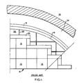
- baffle-barrel region In the irregular space between the core and the core barrel, commonly referred to as the baffle-barrel region are structural components. (See Fig. 1.) Baffle plates which extend the length of the core are supported at several axially spaced radial locations by formers which, in turn, are attached to the core barrel. Radially outward beyond the core barrel is a thermal shield, a downcomer annulus, and then the reactor vessel.
- the baffle plates, formers, core barrel, and thermal shield are typically made of stainless steel; the downcomer annulus and most of the region between the baffle plates and the core barrel is mostly occupied by coolant.
- the reactor coolant typically borated water, circulates through the pressure vessel.
- the coolant enters the reactor vessel and flows downward within the downcomer annulus created by the core barrel and the reactor vessel to the lower region of the reactor vessel below the lower support plate.
- the coolant then flows upward through the core to remove heat generated by the fissioning of the nuclear fuel.
- the heated coolant then flows out of the pressure vessel to a heat exchanger, generally referred to as a steam generator, to generate steam within a secondary loop, which may then be used to drive a turbine generator to generate electrical power.
- the coolant then flows back into the reactor vessel to begin the process anew.
- these applications disclose a method of replacing most of the reactor coolant in the baffle barrel region with a neutron reflecting material, such as stainless steel or zircaloy, to reflect these neutrons back towards the nuclear fuel within the reactor core.
- a neutron reflecting material such as stainless steel or zircaloy
- a nuclear reactor pressure vessel having a core made up of relative ly closely packed generally rectangular elongated components surrounded by a generally cylindrical core barrel to thereby define an irregular area therebetween such that some regions of the core are closer to the core barrel than others, means for reducing the fast neutron flux encountered by the reactor vessel is provided.
- the fast neutron flux reducer comprises a two-stage process: a neutron reflector situated in the irregular area between the core and the core barrel for reflecting fast neutrons back into the core, and a neutron energy reducer disposed around the periphery of the core barrel for reducing the energy of fast neutrons which pass through the reflector.
- the reflector material is constructed of stainless steel, tungsten and/or zirconium oxide.
- the neutron energy reducer is of a high density hydrogenous material such as titanium hydride.
- FIG. 1 shows a typical prior art arrangement of a nuclear reactor pressure vessel 10.
- Generally rectangular or square shaped fuel assemblies 13 are arranged in a relatively closely packed reactor core 16, which is surrounded by a core barrel 19.
- a baffle-barrel region 22 Between the generally cylindrical core barrel 19 and the reactor core 16 is an area commonly referred to as a baffle-barrel region 22.
- baffle plates 25 and formers 28 that provide a structural boundary for the fuel assemblies 13. They extend the length of the core perimeter and are attached to the core barrel 19.
- a thermal shield 31 Surrounding the core barrel 19 is a thermal shield 31.
- the thermal shield 31 Surrounding the core barrel 19 is a thermal shield 31. In between the thermal shield 31 and the vessel wall 10 is the downcomer annulus 34.
- the baffle-barrel region 22 is predominantly composed of metal.
- Fig. 2 shows a top plan view of the design of the present invention incorporating a radial reflector 50 in the baffle-barrel region, as well as a neutron energy, or fast flux, reducer 53 disposed around the periphery of the core barrel 19 in place of the thermal shield 31.
- the reducer 53 may be incorporated into the existing thermal shield 31.
- Fig. 3 shows a cross-sectional view of a typical reflector of the present invention.
- the reflector 50 is preferably comprised of "uncanned" stacked plates 56 of appropriate reflector material.
- the metal used as a reflector 50 is preferably chosen from the group comprised of stainless steel, tungsten, zirconium oxide, or other suitable material having the desired neutron reflecting properties.
- a plurality of plates 56 of such suitable material are stacked one upon the other and secured together by means of a tie rod 59 which is bolted between the top plate 62 and the bottom plate 63 of the neutron reflector module 50.
- Flow holes 66 are provided in each of the plates 56, which vertically align to provide a flow path for coolant, generally designated by arrow 67.
- a plenum 69 is provided to provide for uniformity of flow upward through the reflector 50. Since the reflection of neutrons by the material generates heat within the reflector 50, adequate cooling is to be provided by the flow arrangement of the plenum 69 and the flow holes 66 within the individually stacked plates 56.
- Vertical support for the reflector 50 is provided by a support block 72 and pin 75, which are permanently fixed to the core barrel 19. Additionally, a vertical member 78 of the top plate 62 is bolted 81 to the core barrel 19. In this manner the reflector 50 is supported in the manner of a cantilever beam. Lateral support for the reflector 50 is provided at the bottom by a guide pin 84, which may be an extension of the tie rod 59 or rods, which fits into an opening 87 in the lower core plate 90.
- the design of the reflector 50 and its association with the lower core plate 90, allows the guide pin 84 to thermally grow into the opening 87 as the reflector material is heated by its reflection of fast neutrons.
- this design concept allows the reflector to thermally grow as heat is generated, and to move axially relative to the core barrel 19. It may be desirable to use a structural can (not shown) of minimal wall thickness around the reflector for flow isolation, and to provide a continuous interface for fuel assemblies on the core side.
- a reflector module 50 is easily installed and removed by such design.
- the reflector is removed by unbolting the bolt 81 on the top plate 62, lifting the module sufficiently for the guide pin 84 to clear the lower core plate 90, and then displacing the module laterally to clear the support block 72 before lifting vertically again.
- Fig. 4 shows an enlarged plan view of one section of the reflector 50 of Fig. 2.
- the neutron energy reducing, or thermalization, capacity of the prior art thermal shield 31 is improved by the utilization of a neutron energy reducer 53 secured to the core barrel 19. In this way the thermal shield 31 may be eliminated.
- the fast neutron energy reducer 53 of the present invention is shown.
- the neutron energy reducer 53 is segmented into alternate panels of canisters bearing hydrogenous material 91 and stainless steel 93, which preferably are attached to the outer periphery core barrel 19 in place of the thermal shield 31.
- the canisters of hydrogenous material 91 would preferably be positioned in azimuthal sectors generally corresponding to those regions of the core 16 having the highest neutron flux, commonly referred to as the "flats" regions 96 of the core. In the 335° to 25°, 245° to 295°, 155° to 205°, and 65° to 115° sectors spanned by the "flats" regions 96, the canisters containing high density hydrogenous material 91 are located.
- the hydrogenous material 91 is titanium hydride which has properties quite suitable for this purpose.
- titanium hydride is a very good neutron moderator, or is very good at thermalization of high energy or fast neutrons.
- titanium hydride is denser than water and therefore will encounter and thus slow down more fast energy neutrons than only borated water could. In this manner, any fast neutrons which may pass through the first stage reflector 50, will be slowed down or moderated by the second stage neutron energy reducer 53 to insure that the effects of fast neutrons on the reactor vessel 10 are significantly reduced.
- titanium hydride plates are preferably secured together with a rod, much in the same manner as the reflector 50 is, and secured within a stainless steel canister. Since the effects of fast neutrons on stainless steel are well known, the use of stainless steel as a structural material for enclosing the titanium hydride is desirable. Consequently, it is preferable that the neutron energy reducer 53 be constructed as a stainless steel can, with the titanium hydride neutron flux reducer plates enclosed within.
- the shield cans can be secured or bolted to the outside of the core barrel 19 in a manner which is well known in the art. With this kind of design, the titanium hydride is readily removable and yet does not pose any foreign object concerns during normal reactor operation. Alternatively, titanium hydride panels may be secured directly to the core barrel 19, such as by welding.
- the first stage neutron reflector 50 would be constructed of tungsten stacked plates 56. Since the design of the reflector 50 is an uncanned design, no structural materials other than the stacked plates 56 are necessary. Thus, it is not too important to have a material whose properties are completely known when it is subjected to fast neutrons. Only the tie rod 59 connecting the stacked plates 56 and the support block 72 and pin 75 need be made of such material. Therefore, the neutron reflector 50 adjacent to the flats regions 96 of the core 16 is preferably made of tungsten.
- tungsten provides a more efficient neutron reflector.
- the second stage neutron energy, or fast flux, reducer 53 attached to the core barrel 19 adjacent the downcomer annulus 34 in these regions would be made of a more efficient neutron moderator.
- titanium hydride in these regions for the neutron energy reducer 53 and stainless steel in all others is preferred. In this manner, the incidence of high energy neutron flux around the circumference of the reactor vessel 10 is more uniform. This is most desirable since the effects of any high energy neutrons which may eventually pass through the neutron flux reducer 53, will be more uniform over the entire circumferential surface of the reactor vessel 10.
- the first stage reflector 50 is comprised of tungsten material adjacent to the "flats" regions 96 and stainless steel in the remaining portion of the prior art baffle-barrel zone 22.
- the second stage neutron energy reducer 53 shield canisters contain titanium hydride 91 in these regions, and stainless steel 93 elsewhere.
- the calculated fast flux reduction factor which is defined as the ratio of the fast flux based on the existing design (see Fig. 1) to the fast flux based on the new two-stage design (Fig.
- the design of the present invention having a two stage process first reflects escaping fast neutrons away from the vessel and back into the core, in addition to protecting the vessel, this increases neutron economy within the core.
- the second stage of reducing the energy of any fast neutrons that may pass through the reflector can help increase the efficient operating life of a nuclear power plant, by minimizing the effects of fast neutron flux upon the reactor vessel.
- the second stage neutron energy reducer 53 has been described as being attached to the outer periphery of the core barrel 19, in some existing designs of reactor internals it may not be advantageous to do so.
- the canisters of the neutron energy reducer 53 may be attached to the thermal shield 31 within in the downcomer annulus 34, similar to its attachment to the core barrel 19 itself.
- cutouts may be provided in the thermal shield 31 in those azimuthal sectors adjacent the flats regions 96, so that the titanium hydride 91 canisters or plates may be placed therein, such as by welding. With this type of arrangement, since the thermal shield 31 is made of stainless steel, these type canisters would not have to be added thereto.
Landscapes
- Physics & Mathematics (AREA)
- Engineering & Computer Science (AREA)
- Plasma & Fusion (AREA)
- General Engineering & Computer Science (AREA)
- High Energy & Nuclear Physics (AREA)
- Particle Accelerators (AREA)
- Structure Of Emergency Protection For Nuclear Reactors (AREA)
Applications Claiming Priority (2)
| Application Number | Priority Date | Filing Date | Title |
|---|---|---|---|
| US257917 | 1988-10-14 | ||
| US07/257,917 US4941159A (en) | 1988-10-14 | 1988-10-14 | Low neutron fluence nuclear reactor internals |
Publications (3)
| Publication Number | Publication Date |
|---|---|
| EP0367963A2 true EP0367963A2 (fr) | 1990-05-16 |
| EP0367963A3 EP0367963A3 (en) | 1990-08-29 |
| EP0367963B1 EP0367963B1 (fr) | 1994-08-31 |
Family
ID=22978339
Family Applications (1)
| Application Number | Title | Priority Date | Filing Date |
|---|---|---|---|
| EP89117576A Expired - Lifetime EP0367963B1 (fr) | 1988-10-14 | 1989-09-22 | Composants internes d'un réacteur nucléaire pour flux neutronique bas |
Country Status (4)
| Country | Link |
|---|---|
| US (1) | US4941159A (fr) |
| EP (1) | EP0367963B1 (fr) |
| JP (1) | JPH02150797A (fr) |
| KR (1) | KR900006991A (fr) |
Cited By (5)
| Publication number | Priority date | Publication date | Assignee | Title |
|---|---|---|---|---|
| EP0576195A1 (fr) * | 1992-06-24 | 1993-12-29 | Westinghouse Electric Corporation | Reflecteur de réacteur nucléaire |
| WO1995015565A1 (fr) * | 1993-12-03 | 1995-06-08 | Combustion Engineering, Inc. | Ecran neutre pour une cuve de reacteur |
| EP1387363A4 (fr) * | 2001-04-26 | 2006-11-15 | Mitsubishi Heavy Ind Ltd | Structure et procede permettant de boulonner un reflecteur de neutrons |
| CN101884072A (zh) * | 2007-12-04 | 2010-11-10 | 西屋电气有限责任公司 | 用于反应堆压力容器的中子屏蔽面板 |
| CN108788436A (zh) * | 2018-06-05 | 2018-11-13 | 中国科学院合肥物质科学研究院 | 一种采用置氢金属扩散连接聚变堆材料钨和钢的工艺 |
Families Citing this family (13)
| Publication number | Priority date | Publication date | Assignee | Title |
|---|---|---|---|---|
| JP3845685B2 (ja) * | 2001-07-10 | 2006-11-15 | 独立行政法人 日本原子力研究開発機構 | 放射性廃棄物固体内の核分裂性物質量の非破壊的測定装置 |
| US8615065B2 (en) * | 2009-10-22 | 2013-12-24 | Westinghouse Electric Company Llc | Modular radial neutron reflector |
| US9959944B2 (en) | 2012-04-12 | 2018-05-01 | Bwxt Mpower, Inc. | Self-supporting radial neutron reflector |
| US10923239B2 (en) | 2012-07-09 | 2021-02-16 | Smr Inventec, Llc | Moving an entire nuclear reactor core as a unitary structure |
| US11935663B2 (en) | 2012-05-21 | 2024-03-19 | Smr Inventec, Llc | Control rod drive system for nuclear reactor |
| WO2014011632A2 (fr) * | 2012-07-09 | 2014-01-16 | Holtec International, Inc. | Noyau de combustible nucléaire, cartouche de combustible nucléaire et procédés de chargement de réacteur et/ou de déchargement de réacteur de réacteur nucléaire |
| US9093183B2 (en) * | 2012-12-20 | 2015-07-28 | Westinghouse Electric Company Llc | Heavy radial neutron reflector for pressurized water reactors |
| US20160099083A1 (en) * | 2014-10-01 | 2016-04-07 | Ge-Hitachi Nuclear Energy Americas Llc | Fast flux shield and method of reducing fast neutron fluence at a core shroud of a boiling water reactor using the same |
| JP2017058330A (ja) * | 2015-09-18 | 2017-03-23 | 株式会社東芝 | コアシュラウドおよび原子炉 |
| EP3592493A4 (fr) | 2017-03-08 | 2020-12-02 | BWXT Nuclear Energy, Inc. | Appareil et procédé de réparation de boulon de cloison |
| CN110462748A (zh) * | 2017-03-21 | 2019-11-15 | Smr发明技术有限公司 | 用于小型模块化反应堆的优化核燃料芯设计 |
| CN112489827A (zh) * | 2020-11-26 | 2021-03-12 | 中广核研究院有限公司 | 一种用于紧凑布置小型堆的屏蔽结构 |
| FI20245830A1 (en) * | 2024-06-27 | 2025-12-28 | Steady Energy Oy | Nuclear reactor and method for operating a nuclear reactor |
Family Cites Families (24)
| Publication number | Priority date | Publication date | Assignee | Title |
|---|---|---|---|---|
| US2874307A (en) * | 1947-01-09 | 1959-02-17 | Eugene P Wigner | Reactor shield |
| BE566973A (fr) * | 1957-05-01 | 1900-01-01 | ||
| US2986533A (en) * | 1958-11-12 | 1961-05-30 | Kurtz Jacob | Compact high density radiation screening material containing tungsten |
| US3128234A (en) * | 1960-08-26 | 1964-04-07 | Jr Joseph F Cage | Modular core units for a neutronic reactor |
| NL281992A (fr) * | 1961-09-15 | 1900-01-01 | ||
| US3159550A (en) * | 1962-08-17 | 1964-12-01 | Foster Wheeler Corp | Removable thermal shield |
| US3260650A (en) * | 1963-12-27 | 1966-07-12 | Wilbert A Kalk | Reflector and coolant sealing structure for gas cooled nuclear reactor |
| GB1206640A (en) * | 1967-11-30 | 1970-09-23 | Atomic Power Constr Ltd | Improvements in or relating to nuclear reactors |
| US3682774A (en) * | 1969-09-26 | 1972-08-08 | North American Rockwell | Core clamping system for a nuclear reactor |
| US3785924A (en) * | 1970-09-02 | 1974-01-15 | Combustion Eng | Nuclear reactor core shroud |
| US3708393A (en) * | 1970-12-01 | 1973-01-02 | Atomic Energy Commission | Radial restraint mechanism for reactor core |
| US3868302A (en) * | 1971-05-12 | 1975-02-25 | Westinghouse Electric Corp | Thermal shield of a nuclear reactor |
| FR2168200B1 (fr) * | 1972-01-20 | 1974-12-13 | Creusot Loire | |
| US4080257A (en) * | 1975-11-25 | 1978-03-21 | Westinghouse Electric Corporation | Baffle-former arrangement for nuclear reactor vessel internals |
| FR2481506B1 (fr) * | 1980-04-25 | 1986-08-29 | Framatome Sa | Dispositif de cloisonnement du coeur d'un reacteur nucleaire par des elements amovibles |
| FR2484125A1 (fr) * | 1980-06-06 | 1981-12-11 | Framatome Sa | Dispositif de cloisonnement du coeur d'un reacteur nucleaire |
| FR2499752B1 (fr) * | 1981-02-10 | 1987-07-10 | Commissariat Energie Atomique | Reacteur nucleaire a eau pressurisee |
| FR2535508B1 (fr) * | 1982-10-27 | 1986-07-04 | Framatome Sa | Reacteur nucleaire a rendement ameliore |
| FR2539244B1 (fr) * | 1983-01-12 | 1989-01-27 | Framatome Sa | Dispositif de cloisonnement du coeur d'un reacteur nucleaire a eau sous pression |
| US4576785A (en) * | 1983-06-14 | 1986-03-18 | Carolina Power And Light Company | Reduction in rate of radiation exposure to excore nuclear reactor components |
| US4751043A (en) * | 1984-02-03 | 1988-06-14 | Westinghouse Electric Corp. | Radial neutron reflector |
| GB2154046B (en) * | 1984-02-03 | 1988-06-22 | Westinghouse Electric Corp | Radial neutron reflector |
| US4743423A (en) * | 1984-09-28 | 1988-05-10 | Westinghouse Electric Corp. | Neutron shield panel arrangement for a nuclear reactor pressure vessel |
| US4731220A (en) * | 1985-08-14 | 1988-03-15 | Westinghouse Electric Corp. | Neutron reflector |
-
1988
- 1988-10-14 US US07/257,917 patent/US4941159A/en not_active Expired - Fee Related
-
1989
- 1989-09-22 EP EP89117576A patent/EP0367963B1/fr not_active Expired - Lifetime
- 1989-10-13 JP JP1265328A patent/JPH02150797A/ja active Pending
- 1989-10-14 KR KR1019890014782A patent/KR900006991A/ko not_active Withdrawn
Cited By (10)
| Publication number | Priority date | Publication date | Assignee | Title |
|---|---|---|---|---|
| EP0576195A1 (fr) * | 1992-06-24 | 1993-12-29 | Westinghouse Electric Corporation | Reflecteur de réacteur nucléaire |
| US5319692A (en) * | 1992-06-24 | 1994-06-07 | Westinghouse Electric Corp. | Nuclear reactor reflector |
| WO1995015565A1 (fr) * | 1993-12-03 | 1995-06-08 | Combustion Engineering, Inc. | Ecran neutre pour une cuve de reacteur |
| US5436945A (en) * | 1993-12-03 | 1995-07-25 | Combustion Engineering, Inc. | Shadow shielding |
| EP1387363A4 (fr) * | 2001-04-26 | 2006-11-15 | Mitsubishi Heavy Ind Ltd | Structure et procede permettant de boulonner un reflecteur de neutrons |
| US7873138B2 (en) | 2001-04-26 | 2011-01-18 | Mitsubishi Heavy Industries, Ltd. | Structure and method for bolting neutron reflector |
| CN101884072A (zh) * | 2007-12-04 | 2010-11-10 | 西屋电气有限责任公司 | 用于反应堆压力容器的中子屏蔽面板 |
| EP2227814A4 (fr) * | 2007-12-04 | 2011-03-09 | Westinghouse Electric Corp | Panneaux de protection neutroniques pour cuves sous pression de réacteur |
| CN101884072B (zh) * | 2007-12-04 | 2013-03-27 | 西屋电气有限责任公司 | 用于反应堆压力容器的中子屏蔽面板 |
| CN108788436A (zh) * | 2018-06-05 | 2018-11-13 | 中国科学院合肥物质科学研究院 | 一种采用置氢金属扩散连接聚变堆材料钨和钢的工艺 |
Also Published As
| Publication number | Publication date |
|---|---|
| KR900006991A (ko) | 1990-05-09 |
| US4941159A (en) | 1990-07-10 |
| EP0367963A3 (en) | 1990-08-29 |
| EP0367963B1 (fr) | 1994-08-31 |
| JPH02150797A (ja) | 1990-06-11 |
Similar Documents
| Publication | Publication Date | Title |
|---|---|---|
| US4941159A (en) | Low neutron fluence nuclear reactor internals | |
| US4285769A (en) | Control cell nuclear reactor core | |
| JP2511581B2 (ja) | 沸騰水型原子炉炉心及び沸騰水型原子炉 | |
| US6512805B1 (en) | Light water reactor core and fuel assembly | |
| US4251321A (en) | Nuclear reactor utilizing plutonium | |
| Dubberley et al. | SuperPRISM oxide and metal fuel core designs | |
| EP0180187B1 (fr) | Réacteur nucléaire muni d'écrans contre l'irradiation des soudures d'enceinte sous pression | |
| EP0538414A4 (en) | Seed and blanket fuel arrangement for dual-phase nuclear reactors | |
| EP0094255B1 (fr) | Région de puissance maximale pour un réacteur nucléaire | |
| US4370296A (en) | Toroidal fusion reactor having ohmic heating coil substantially adjacent toroidal fusion region | |
| KR920007739B1 (ko) | 제어봉 클러스터 조립체 | |
| US4370295A (en) | Fusion-fission power generating device having fissile-fertile material within the region of the toroidal field coils generating means | |
| US4707329A (en) | Nuclear reactor control rod with uniformly changeable axial worth | |
| Hong et al. | The encapsulated nuclear heat source (ENHS) reactor core design | |
| US4820478A (en) | Nuclear reactor control rod with uniformly changeable axial worth | |
| US5610959A (en) | Hafnium doped replacement rod for nuclear fuel reconstitution | |
| KR20070100818A (ko) | 가압수형 원자로의 연료 집합체 및 연료 집합체의 설계방법 | |
| GB1029712A (en) | Improvements in or relating to nuclear reactors | |
| Mansani et al. | Proposed sub-criticality level for an 80 MWth Lead-Bismuth-cooled ADS | |
| Furuta et al. | Design and safety study of power producing fusion-fission hybrid reactor | |
| Müller et al. | DESIGN AND EVALUATION OF A STEAM COOLED FAST BREEDER REACTOR OF 1000 MW (e) | |
| Frischengruber et al. | 150 DEVELOPMENT POTENTIAL AND ADVANCED FUEL CYCLES IN KWU TYPE PHWRs | |
| Sawada et al. | Characteristics of fuel melting and relocation in metallic-fueled fast reactor core and its feasibility for eliminating recriticality | |
| Giraud et al. | Preliminary design of a gas-cooled accelerator driven system demonstrator | |
| Ueda et al. | Design Features of APWR in Japan |
Legal Events
| Date | Code | Title | Description |
|---|---|---|---|
| PUAI | Public reference made under article 153(3) epc to a published international application that has entered the european phase |
Free format text: ORIGINAL CODE: 0009012 |
|
| AK | Designated contracting states |
Kind code of ref document: A2 Designated state(s): BE CH ES FR GB IT LI SE |
|
| PUAL | Search report despatched |
Free format text: ORIGINAL CODE: 0009013 |
|
| AK | Designated contracting states |
Kind code of ref document: A3 Designated state(s): BE CH ES FR GB IT LI SE |
|
| 17P | Request for examination filed |
Effective date: 19901018 |
|
| 17Q | First examination report despatched |
Effective date: 19930331 |
|
| GRAA | (expected) grant |
Free format text: ORIGINAL CODE: 0009210 |
|
| AK | Designated contracting states |
Kind code of ref document: B1 Designated state(s): BE CH ES FR GB IT LI SE |
|
| PG25 | Lapsed in a contracting state [announced via postgrant information from national office to epo] |
Ref country code: IT Free format text: LAPSE BECAUSE OF FAILURE TO SUBMIT A TRANSLATION OF THE DESCRIPTION OR TO PAY THE FEE WITHIN THE PRE;WARNING: LAPSES OF ITALIAN PATENTS WITH EFFECTIVE DATE BEFORE 2007 MAY HAVE OCCURRED AT ANY TIME BEFORE 2007. THE CORRECT EFFECTIVE DATE MAY BE DIFFERENT FROM THE ONE RECORDED.SCRIBED TIME-LIMIT Effective date: 19940831 Ref country code: LI Effective date: 19940831 Ref country code: ES Free format text: THE PATENT HAS BEEN ANNULLED BY A DECISION OF A NATIONAL AUTHORITY Effective date: 19940831 Ref country code: CH Effective date: 19940831 Ref country code: BE Effective date: 19940831 Ref country code: FR Effective date: 19940831 |
|
| PG25 | Lapsed in a contracting state [announced via postgrant information from national office to epo] |
Ref country code: SE Effective date: 19941130 |
|
| REG | Reference to a national code |
Ref country code: CH Ref legal event code: PL |
|
| EN | Fr: translation not filed | ||
| PLBE | No opposition filed within time limit |
Free format text: ORIGINAL CODE: 0009261 |
|
| STAA | Information on the status of an ep patent application or granted ep patent |
Free format text: STATUS: NO OPPOSITION FILED WITHIN TIME LIMIT |
|
| 26N | No opposition filed | ||
| PGFP | Annual fee paid to national office [announced via postgrant information from national office to epo] |
Ref country code: GB Payment date: 19990806 Year of fee payment: 11 |
|
| PG25 | Lapsed in a contracting state [announced via postgrant information from national office to epo] |
Ref country code: GB Free format text: LAPSE BECAUSE OF NON-PAYMENT OF DUE FEES Effective date: 20000922 |
|
| GBPC | Gb: european patent ceased through non-payment of renewal fee |
Effective date: 20000922 |