EP0367969B1 - Halterung und Zentrierungseinrichtung für Leitschaufelträger einer Gasturbine - Google Patents
Halterung und Zentrierungseinrichtung für Leitschaufelträger einer Gasturbine Download PDFInfo
- Publication number
- EP0367969B1 EP0367969B1 EP89117886A EP89117886A EP0367969B1 EP 0367969 B1 EP0367969 B1 EP 0367969B1 EP 89117886 A EP89117886 A EP 89117886A EP 89117886 A EP89117886 A EP 89117886A EP 0367969 B1 EP0367969 B1 EP 0367969B1
- Authority
- EP
- European Patent Office
- Prior art keywords
- vane
- combustion turbine
- torque plate
- turbine
- combustion
- Prior art date
- Legal status (The legal status is an assumption and is not a legal conclusion. Google has not performed a legal analysis and makes no representation as to the accuracy of the status listed.)
- Expired - Lifetime
Links
Images

Classifications
-
- F—MECHANICAL ENGINEERING; LIGHTING; HEATING; WEAPONS; BLASTING
- F01—MACHINES OR ENGINES IN GENERAL; ENGINE PLANTS IN GENERAL; STEAM ENGINES
- F01D—NON-POSITIVE DISPLACEMENT MACHINES OR ENGINES, e.g. STEAM TURBINES
- F01D9/00—Stators
- F01D9/02—Nozzles; Nozzle boxes; Stator blades; Guide conduits, e.g. individual nozzles
-
- F—MECHANICAL ENGINEERING; LIGHTING; HEATING; WEAPONS; BLASTING
- F01—MACHINES OR ENGINES IN GENERAL; ENGINE PLANTS IN GENERAL; STEAM ENGINES
- F01D—NON-POSITIVE DISPLACEMENT MACHINES OR ENGINES, e.g. STEAM TURBINES
- F01D9/00—Stators
- F01D9/02—Nozzles; Nozzle boxes; Stator blades; Guide conduits, e.g. individual nozzles
- F01D9/04—Nozzles; Nozzle boxes; Stator blades; Guide conduits, e.g. individual nozzles forming ring or sector
-
- F—MECHANICAL ENGINEERING; LIGHTING; HEATING; WEAPONS; BLASTING
- F01—MACHINES OR ENGINES IN GENERAL; ENGINE PLANTS IN GENERAL; STEAM ENGINES
- F01D—NON-POSITIVE DISPLACEMENT MACHINES OR ENGINES, e.g. STEAM TURBINES
- F01D25/00—Component parts, details, or accessories, not provided for in, or of interest apart from, other groups
- F01D25/24—Casings; Casing parts, e.g. diaphragms, casing fastenings
- F01D25/246—Fastening of diaphragms or stator-rings
-
- F—MECHANICAL ENGINEERING; LIGHTING; HEATING; WEAPONS; BLASTING
- F05—INDEXING SCHEMES RELATING TO ENGINES OR PUMPS IN VARIOUS SUBCLASSES OF CLASSES F01-F04
- F05B—INDEXING SCHEME RELATING TO WIND, SPRING, WEIGHT, INERTIA OR LIKE MOTORS, TO MACHINES OR ENGINES FOR LIQUIDS COVERED BY SUBCLASSES F03B, F03D AND F03G
- F05B2230/00—Manufacture
- F05B2230/60—Assembly methods
- F05B2230/604—Assembly methods using positioning or alignment devices for aligning or centering, e.g. pins
- F05B2230/608—Assembly methods using positioning or alignment devices for aligning or centering, e.g. pins for adjusting the position or the alignment, e.g. wedges or excenters
-
- F—MECHANICAL ENGINEERING; LIGHTING; HEATING; WEAPONS; BLASTING
- F05—INDEXING SCHEMES RELATING TO ENGINES OR PUMPS IN VARIOUS SUBCLASSES OF CLASSES F01-F04
- F05D—INDEXING SCHEME FOR ASPECTS RELATING TO NON-POSITIVE-DISPLACEMENT MACHINES OR ENGINES, GAS-TURBINES OR JET-PROPULSION PLANTS
- F05D2230/00—Manufacture
- F05D2230/60—Assembly methods
- F05D2230/64—Assembly methods using positioning or alignment devices for aligning or centring, e.g. pins
- F05D2230/644—Assembly methods using positioning or alignment devices for aligning or centring, e.g. pins for adjusting the position or the alignment, e.g. wedges or eccenters
Definitions
- This invention relates generally to combustion or gas turbines, and more particularly to combustion turbines having vane segment support and alignment devices.
- combustion turbines are in electric-generating use. Since they are readily started, combustion turbines are primarily used by electric utility companies for peak-load duty.
- a typical combustion turbine is comprised of four basic portions: (1) an inlet portion; (2) a compressor portion; (3) a combustor portion; and (4) an exhaust portion. Air entering the combustion turbine at its inlet portion is compressed adiabatically in the compressor portion, and is mixed with a fuel and heated at a constant pressure in the combustor portion. Thereafter, the heated air is discharged through the exhaust portion with a resulting adiabatic expansion of the gases completing the basic combustion turbine cycle.
- This basic combustion turbine cycle is generally referred to as the Brayton or Joule cycle.
- a major reason for reduced turbine efficiency is misalignment of the vane segments in a turbine with respect to a stationary cylinder assembly. It is generally desirable to closely align the vane segments radially between the inner and outer cylinders of the turbine unit so that aerodynamic drag on the vane segments is minimized. The aerodynamic forces should be taken up directly by the casing of the combustion turbine.
- the present invention resides in a combustion turbine having an inlet air compressor portion, a combustor portion and an exhaust portion and a rotor having rows of turbine blades mounted thereon and segmented vane structures supported in said turbine between outer and inner cylinders adjacent to the first row of turbine blades for directing the combustion gases onto said blades, characterized in that the vane segments of said segmented vane structures are supported at their outer circumference by said outer cylinder and that they have radial slots formed at their radially inner ends and further that bushing assemblies are supported in openings formed in support structure which is mounted on said inner cylinder, said assemblies having eccentric pins projecting into the radial slots in said vane segments and being angularly adjustably mounted in said openings so as to permit adjustment of the inner support for said vane segments.
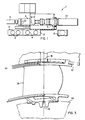
- FIG 1 shows the layout of a typical electric generating plant 2 utilizing a well-known combustion turbine 4 (such as the model W-501D single shaft, heavy duty combustion turbine that is manufactured by the Combustion Turbine Systems Division of Westinghouse Electric Corporation).
- the plant 2 includes a generator 6 driven by the turbine 4, a starter package 8, an electrical package 10 having glycol cooler 12, a mechanical package 14 having an oil cooler 16, and an air cooler 18, each of which supports the operating turbine 4.
- a silencer 20 is disposed at the turbine exhaust end. Terminals 22 are provided at the generator 6 for conducting the generated electricity therefrom.
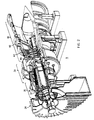
- Figure 2 is an isometric view of the turbine 4 in greater detail.
- the turbine 4 generally has an inlet portion 24, a compressor portion 26, a combustor portion 28, and an exhaust portion 30.
- Air entering the turbine 4 at its inlet portion 24 is compressed adiabatically in a compressor portion 26, and is mixed with a fuel and heated at a constant pressure in the combustor portion 28.
- the heated fuel/air gases are thereafter discharged from the combustor portion 28 through the exhaust portion 30.
- the compressor portion 26, is of an axial flow configuration having a rotor 32, which includes a plurality of rotating blades 34 mounted on a shaft 36.
- a casing 40 encloses the entire turbine.
- Figure 3 shows a basic vane segment support arrangement wherein the vane segment 38 is mounted between an outer cylinder 42 and an inner cylinder 44. Vane segment 38 is generally fixed to outer cylinder 42 at 46.
- the vane segment 38 is provided with a slot 48 by way of which it is supported circumferentially with respect to inner cylinder 44 while permitting radial expansion of the vane segment relative to the inner cylinder 44.
- the vane segment 38 is adjustably engaged with the inner cylinder 44.
- Slot 48 in vane segment 38 receives a pin 50 which is part of an eccentric assembly 52 mounted on the inner cylinder 44 thereby allowing pin 50 to adjust the vane segment 38 as the eccentric bushing assembly 52 is rotated.
- the bushing assembly 52 is supported by a torque plate 56 which is mounted to the inner cylinder 44 by bolts 72 and which has a bore 58 extending therethrough adjacent the slot 48 of an adjacent vane segment 38.
- the bore 58 has a central bushing assembly support section 59, a splined locking section 60 at its inner end and a threaded outer end receiving a cover plate 54.
- the bushing assembly 52 has a large diameter cylindrical mounting portion disposed in the support section 59 of the bore 58 and a splined locking portion 62 received in the locking section 60 from which the pin 50 projects eccentrically into the vane segment slot 48.
- the locking portion 62 is relatively short so that, upon loosening of the cover plate 54, the bushing assembly can be retracted so as to disengage it from the locking section 60 while the large diameter mounting portion of the bushing assembly 52 remains rotatably supported in the support section 59. The assembly may then be rotated for adjustment of the vane segment 38 and then re-engaged with the splined locking section 60.
- the cover plate 54 firmly screwed into the threaded outer end of the bore 58 retains the bushing assembly in the desired position to properly support the vane segments 38.
- the threads on the torque plate 56 and cover plate 54 are peened at 70 to prevent loosening of the cover plate 54.
- a small axial clearance 64 is provided between the torque plate 56 and vane segment 38 to permit radial growth movement of the vane segment 38.
- Figure 5 is a view of the vane segment alignment device viewed along the 5-5 line of Figure 4.
- Figure 5 illustrates the peening and splining arrangement of the eccentric bushing 52 with the torque plate 56 and cover plate 54. The peening area of the torque plate and cover plate is shown at 68.
Landscapes
- Engineering & Computer Science (AREA)
- Mechanical Engineering (AREA)
- General Engineering & Computer Science (AREA)
- Turbine Rotor Nozzle Sealing (AREA)
- Structures Of Non-Positive Displacement Pumps (AREA)
- Control Of Turbines (AREA)
Claims (5)
Applications Claiming Priority (2)
| Application Number | Priority Date | Filing Date | Title |
|---|---|---|---|
| US259811 | 1988-10-19 | ||
| US07/259,811 US4890978A (en) | 1988-10-19 | 1988-10-19 | Method and apparatus for vane segment support and alignment in combustion turbines |
Publications (2)
| Publication Number | Publication Date |
|---|---|
| EP0367969A1 EP0367969A1 (de) | 1990-05-16 |
| EP0367969B1 true EP0367969B1 (de) | 1992-06-03 |
Family
ID=22986493
Family Applications (1)
| Application Number | Title | Priority Date | Filing Date |
|---|---|---|---|
| EP89117886A Expired - Lifetime EP0367969B1 (de) | 1988-10-19 | 1989-09-27 | Halterung und Zentrierungseinrichtung für Leitschaufelträger einer Gasturbine |
Country Status (11)
| Country | Link |
|---|---|
| US (1) | US4890978A (de) |
| EP (1) | EP0367969B1 (de) |
| JP (1) | JPH02149702A (de) |
| KR (1) | KR0165669B1 (de) |
| CN (1) | CN1018273B (de) |
| AR (1) | AR241034A1 (de) |
| AU (1) | AU617005B2 (de) |
| CA (1) | CA1318853C (de) |
| DE (1) | DE68901704T2 (de) |
| IE (1) | IE893018L (de) |
| MX (1) | MX163938B (de) |
Families Citing this family (29)
| Publication number | Priority date | Publication date | Assignee | Title |
|---|---|---|---|---|
| US5141394A (en) * | 1990-10-10 | 1992-08-25 | Westinghouse Electric Corp. | Apparatus and method for supporting a vane segment in a gas turbine |
| CA2082709A1 (en) * | 1991-12-02 | 1993-06-03 | Srinivasan Venkatasubbu | Variable stator vane assembly for an axial flow compressor of a gas turbine engine |
| US5271714A (en) * | 1992-07-09 | 1993-12-21 | General Electric Company | Turbine nozzle support arrangement |
| US5421703A (en) * | 1994-05-25 | 1995-06-06 | General Electric Company | Positively retained vane bushing for an axial flow compressor |
| US5513547A (en) * | 1995-01-06 | 1996-05-07 | Westinghouse Electric Corporation | Combustion turbine alignment method and apparatus |
| US5609467A (en) * | 1995-09-28 | 1997-03-11 | Cooper Cameron Corporation | Floating interturbine duct assembly for high temperature power turbine |
| US5618161A (en) * | 1995-10-17 | 1997-04-08 | Westinghouse Electric Corporation | Apparatus for restraining motion of a turbo-machine stationary vane |
| US5921749A (en) * | 1996-10-22 | 1999-07-13 | Siemens Westinghouse Power Corporation | Vane segment support and alignment device |
| US5848874A (en) * | 1997-05-13 | 1998-12-15 | United Technologies Corporation | Gas turbine stator vane assembly |
| US6364606B1 (en) | 2000-11-08 | 2002-04-02 | Allison Advanced Development Company | High temperature capable flange |
| JP3825279B2 (ja) * | 2001-06-04 | 2006-09-27 | 三菱重工業株式会社 | ガスタービン |
| US7008170B2 (en) * | 2004-03-26 | 2006-03-07 | Siemens Westinghouse Power Corporation | Compressor diaphragm with axial preload |
| US7114920B2 (en) * | 2004-06-25 | 2006-10-03 | Pratt & Whitney Canada Corp. | Shroud and vane segments having edge notches |
| JP2007046540A (ja) * | 2005-08-10 | 2007-02-22 | Hitachi Ltd | タービンのシール構造 |
| JP4950793B2 (ja) * | 2006-07-26 | 2012-06-13 | 岡本株式会社 | 靴下 |
| EP1965042A1 (de) * | 2007-03-02 | 2008-09-03 | Siemens Aktiengesellschaft | Mittenausrichtung und Fixerung von Statorteilen |
| US7758307B2 (en) * | 2007-05-17 | 2010-07-20 | Siemens Energy, Inc. | Wear minimization system for a compressor diaphragm |
| FR2923530B1 (fr) * | 2007-11-09 | 2014-04-04 | Snecma | Raccordement de bras radiaux a une virole circulaire par des axes et des entretoises |
| US8182207B2 (en) * | 2008-03-17 | 2012-05-22 | General Electric Company | Inner turbine shell support configuration and methods |
| US8043044B2 (en) * | 2008-09-11 | 2011-10-25 | General Electric Company | Load pin for compressor square base stator and method of use |
| US8443607B2 (en) * | 2009-02-20 | 2013-05-21 | General Electric Company | Coaxial fuel and air premixer for a gas turbine combustor |
| US8231338B2 (en) | 2009-05-05 | 2012-07-31 | General Electric Company | Turbine shell with pin support |
| US20100303610A1 (en) * | 2009-05-29 | 2010-12-02 | United Technologies Corporation | Cooled gas turbine stator assembly |
| US8794587B2 (en) | 2009-09-02 | 2014-08-05 | Siemens Aktiengesellschaft | Mounting apparatus |
| US8453454B2 (en) | 2010-04-14 | 2013-06-04 | General Electric Company | Coannular oil injection nozzle |
| EP2594743A1 (de) | 2011-11-21 | 2013-05-22 | Siemens Aktiengesellschaft | Exzentrische Justierstifte für eine Statorscheibe eines Gasturbinentriebwerks |
| EP2952688A1 (de) | 2014-06-02 | 2015-12-09 | Siemens Aktiengesellschaft | Verfahren zur Montage einer Statorstufe eines Gasturbinentriebwerks |
| DE102016202519A1 (de) * | 2016-02-18 | 2017-08-24 | MTU Aero Engines AG | Leitschaufelsegment für eine Strömungsmaschine |
| CN112761734B (zh) * | 2021-04-07 | 2021-07-20 | 中国联合重型燃气轮机技术有限公司 | 用于燃气轮机静叶持环的调节装置和燃气轮机 |
Family Cites Families (19)
| Publication number | Priority date | Publication date | Assignee | Title |
|---|---|---|---|---|
| GB701101A (en) * | 1950-06-29 | 1953-12-16 | Rolls Royce | Improvements in or relating to gas-turbine engines |
| US2942844A (en) * | 1952-12-22 | 1960-06-28 | Gen Motors Corp | Turbine nozzle |
| US2819871A (en) * | 1954-09-07 | 1958-01-14 | John R Mcveigh | Vane structure |
| BE556572A (de) * | 1955-08-16 | |||
| US3070352A (en) * | 1957-11-06 | 1962-12-25 | Gen Motors Corp | Vane ring assembly |
| US2971333A (en) * | 1958-05-14 | 1961-02-14 | Gen Electric | Adjustable gas impingement turbine nozzles |
| DE1178253B (de) * | 1962-03-03 | 1964-09-17 | Maschf Augsburg Nuernberg Ag | Axial-durchstroemte Kreiselradmaschine mit einstellbarem Deckband |
| CH491288A (de) * | 1968-05-20 | 1970-05-31 | Sulzer Ag | Halterung für den Leitschaufelträger einer mehrstufigen Gasturbine |
| DE2121707C3 (de) * | 1971-05-03 | 1974-06-20 | Motoren- Und Turbinen-Union Friedrichshafen Gmbh, 7990 Friedrichshafen | Leitschaufelkranz |
| DE2165529A1 (de) * | 1971-12-30 | 1973-07-05 | Kloeckner Humboldt Deutz Ag | Einrichtung zum zentrieren und fixieren eines koerpers |
| GB1387866A (en) * | 1972-06-21 | 1975-03-19 | Rolls Royce | Aerofoil members for gas turbine engines |
| US3829233A (en) * | 1973-06-27 | 1974-08-13 | Westinghouse Electric Corp | Turbine diaphragm seal structure |
| US4127357A (en) * | 1977-06-24 | 1978-11-28 | General Electric Company | Variable shroud for a turbomachine |
| GB2042646B (en) * | 1979-02-20 | 1982-09-22 | Rolls Royce | Rotor blade tip clearance control for gas turbine engine |
| US4286921A (en) * | 1979-12-13 | 1981-09-01 | Westinghouse Electric Corp. | Locking structure for an alignment bushing of a combustion turbine engine |
| GB2071776A (en) * | 1980-03-19 | 1981-09-23 | Rolls Royce | Stator Vane Assembly |
| US4720236A (en) * | 1984-12-21 | 1988-01-19 | United Technologies Corporation | Coolable stator assembly for a gas turbine engine |
| JPS63170505A (ja) * | 1987-01-09 | 1988-07-14 | Toshiba Corp | ノズルダイヤフラム |
| DE4135210A1 (de) * | 1991-10-25 | 1993-04-29 | Broadcast Television Syst | Verfahren und schaltung zur korrektur von abschattungen |
-
1988
- 1988-10-19 US US07/259,811 patent/US4890978A/en not_active Expired - Lifetime
-
1989
- 1989-09-21 IE IE893018A patent/IE893018L/xx unknown
- 1989-09-25 AU AU41660/89A patent/AU617005B2/en not_active Ceased
- 1989-09-27 EP EP89117886A patent/EP0367969B1/de not_active Expired - Lifetime
- 1989-09-27 DE DE8989117886T patent/DE68901704T2/de not_active Expired - Lifetime
- 1989-09-29 CA CA000614527A patent/CA1318853C/en not_active Expired - Fee Related
- 1989-10-16 MX MX17961A patent/MX163938B/es unknown
- 1989-10-18 CN CN89107677A patent/CN1018273B/zh not_active Expired
- 1989-10-18 JP JP1269253A patent/JPH02149702A/ja active Pending
- 1989-10-19 KR KR1019890015064A patent/KR0165669B1/ko not_active Expired - Lifetime
- 1989-10-19 AR AR315223A patent/AR241034A1/es active
Also Published As
| Publication number | Publication date |
|---|---|
| DE68901704T2 (de) | 1992-12-17 |
| AU4166089A (en) | 1990-04-26 |
| IE893018L (en) | 1990-04-19 |
| CN1018273B (zh) | 1992-09-16 |
| CA1318853C (en) | 1993-06-08 |
| MX163938B (es) | 1992-07-02 |
| AR241034A2 (es) | 1991-04-30 |
| AU617005B2 (en) | 1991-11-14 |
| KR0165669B1 (ko) | 1998-12-15 |
| US4890978A (en) | 1990-01-02 |
| AR241034A1 (es) | 1991-04-30 |
| DE68901704D1 (de) | 1992-07-09 |
| CN1042397A (zh) | 1990-05-23 |
| JPH02149702A (ja) | 1990-06-08 |
| EP0367969A1 (de) | 1990-05-16 |
| KR900006648A (ko) | 1990-05-08 |
Similar Documents
| Publication | Publication Date | Title |
|---|---|---|
| EP0367969A1 (de) | Halterung und Zentrierungseinrichtung für Leitschaufelträger einer Gasturbine | |
| EP0934456B1 (de) | Halterung und zentrierungseinrichtung für leitschaufelträger | |
| CA1333472C (en) | Compressor diaphragm assembly | |
| US6095750A (en) | Turbine nozzle assembly | |
| EP1655457B1 (de) | Gasturbine und Verfahren zu deren Montage | |
| US5281087A (en) | Industrial gas turbine engine with dual panel variable vane assembly | |
| US5211537A (en) | Compressor vane lock | |
| EP2110531B1 (de) | Abgasturbolader | |
| US20040223846A1 (en) | Methods and apparatus for controlling gas turbine engine rotor tip clearances | |
| EP2204534B1 (de) | Synchronisierung von Gasturbinenschaufeln | |
| US20050120701A1 (en) | Nozzle bolting arrangement for a turbine | |
| EP0475771B1 (de) | Kompressorgehäuse-Konstruktion | |
| US20100054929A1 (en) | Turbine airfoil clocking | |
| CA2053036A1 (en) | Apparatus and method for supporting a vane segment in a gas turbine | |
| US8251647B2 (en) | Guide device | |
| EP1793095B1 (de) | Apparat zum Zusammenbauen eines Gasturbinentriebwerks | |
| US12173609B2 (en) | Pre-swirler adjustability in gas turbine engine | |
| CN112253264A (zh) | 用于调控转静子间隙和同心状态的装置和方法 | |
| US11015483B2 (en) | High pressure compressor flow path flanges with leak resistant plates for improved compressor efficiency and cyclic life | |
| US11415010B1 (en) | Turbine nozzle and gas turbine including the same | |
| EP4613973A1 (de) | Turbinenschaufel und gasturbine damit | |
| CN113944517B (zh) | 一种局部增压式径流涡轮增压系统转子密封结构 | |
| CN114033499B (zh) | 一种径流涡轮发电系统转子大压力梯度高效密封结构 | |
| US12247516B2 (en) | Counter-rotating gas turbine engines including turbine sections with separable torque frames |
Legal Events
| Date | Code | Title | Description |
|---|---|---|---|
| PUAI | Public reference made under article 153(3) epc to a published international application that has entered the european phase |
Free format text: ORIGINAL CODE: 0009012 |
|
| AK | Designated contracting states |
Kind code of ref document: A1 Designated state(s): BE CH DE FR GB IT LI NL SE |
|
| 17P | Request for examination filed |
Effective date: 19900914 |
|
| 17Q | First examination report despatched |
Effective date: 19910801 |
|
| GRAA | (expected) grant |
Free format text: ORIGINAL CODE: 0009210 |
|
| ITF | It: translation for a ep patent filed | ||
| AK | Designated contracting states |
Kind code of ref document: B1 Designated state(s): BE CH DE FR GB IT LI NL SE |
|
| PG25 | Lapsed in a contracting state [announced via postgrant information from national office to epo] |
Ref country code: NL Effective date: 19920603 Ref country code: SE Effective date: 19920603 Ref country code: BE Effective date: 19920603 |
|
| ET | Fr: translation filed | ||
| REF | Corresponds to: |
Ref document number: 68901704 Country of ref document: DE Date of ref document: 19920709 |
|
| PGFP | Annual fee paid to national office [announced via postgrant information from national office to epo] |
Ref country code: CH Payment date: 19920811 Year of fee payment: 4 |
|
| NLV1 | Nl: lapsed or annulled due to failure to fulfill the requirements of art. 29p and 29m of the patents act | ||
| PLBE | No opposition filed within time limit |
Free format text: ORIGINAL CODE: 0009261 |
|
| STAA | Information on the status of an ep patent application or granted ep patent |
Free format text: STATUS: NO OPPOSITION FILED WITHIN TIME LIMIT |
|
| 26N | No opposition filed | ||
| PG25 | Lapsed in a contracting state [announced via postgrant information from national office to epo] |
Ref country code: CH Effective date: 19930930 Ref country code: LI Effective date: 19930930 |
|
| REG | Reference to a national code |
Ref country code: CH Ref legal event code: PL |
|
| PGFP | Annual fee paid to national office [announced via postgrant information from national office to epo] |
Ref country code: GB Payment date: 19940627 Year of fee payment: 6 |
|
| PG25 | Lapsed in a contracting state [announced via postgrant information from national office to epo] |
Ref country code: GB Effective date: 19950927 |
|
| GBPC | Gb: european patent ceased through non-payment of renewal fee |
Effective date: 19950927 |
|
| PGFP | Annual fee paid to national office [announced via postgrant information from national office to epo] |
Ref country code: FR Payment date: 19960910 Year of fee payment: 8 |
|
| PG25 | Lapsed in a contracting state [announced via postgrant information from national office to epo] |
Ref country code: FR Free format text: THE PATENT HAS BEEN ANNULLED BY A DECISION OF A NATIONAL AUTHORITY Effective date: 19970930 |
|
| REG | Reference to a national code |
Ref country code: FR Ref legal event code: ST |
|
| PGFP | Annual fee paid to national office [announced via postgrant information from national office to epo] |
Ref country code: IT Payment date: 20080924 Year of fee payment: 20 |
|
| PGFP | Annual fee paid to national office [announced via postgrant information from national office to epo] |
Ref country code: DE Payment date: 20081121 Year of fee payment: 20 |