EP0367975B1 - Structure de coffret préfabriqué pour sous-station - Google Patents
Structure de coffret préfabriqué pour sous-station Download PDFInfo
- Publication number
- EP0367975B1 EP0367975B1 EP19890118191 EP89118191A EP0367975B1 EP 0367975 B1 EP0367975 B1 EP 0367975B1 EP 19890118191 EP19890118191 EP 19890118191 EP 89118191 A EP89118191 A EP 89118191A EP 0367975 B1 EP0367975 B1 EP 0367975B1
- Authority
- EP
- European Patent Office
- Prior art keywords
- box members
- members
- box
- connection openings
- housing structure
- Prior art date
- Legal status (The legal status is an assumption and is not a legal conclusion. Google has not performed a legal analysis and makes no representation as to the accuracy of the status listed.)
- Expired - Lifetime
Links
Images


Classifications
-
- H—ELECTRICITY
- H02—GENERATION; CONVERSION OR DISTRIBUTION OF ELECTRIC POWER
- H02B—BOARDS, SUBSTATIONS OR SWITCHING ARRANGEMENTS FOR THE SUPPLY OR DISTRIBUTION OF ELECTRIC POWER
- H02B7/00—Enclosed substations, e.g. compact substations
-
- H—ELECTRICITY
- H02—GENERATION; CONVERSION OR DISTRIBUTION OF ELECTRIC POWER
- H02B—BOARDS, SUBSTATIONS OR SWITCHING ARRANGEMENTS FOR THE SUPPLY OR DISTRIBUTION OF ELECTRIC POWER
- H02B13/00—Arrangement of switchgear in which switches are enclosed in, or structurally associated with, a casing, e.g. cubicle
- H02B13/005—Electrical connection between switchgear cells
Definitions
- This invention relates to a prefabricated type housing structure for substation electrical equipment as described in the introductory clause of claim 1.
- Electric power substations generally comprise an assembly of electrical equipment for the transmission, transformation, distribution, and switching of the electric energy in an electric power system.
- the housing structures for accomodating the substation electrical equipment were built on the substation sites. This, however, entails much cost and labor; in addition, it is hard by this on-site building method to maintain high quality.
- housing structures for substation electrical equipment have already been proposed wherein factory-built housing units are assembled on the substation sites.
- Figs. 1 and 2 show, in a plan and a front view respectively, an example of such a housing structure for substations, which is disclosed in Japanese laid-open utility model application No. 60-190106.
- box members 1 (four in number in the figure) each consist of four side walls, a bottom plate, and a top plate (removed in the figure to show the interior); each box member 1 is provided with a pair of connection openings 1a and 1b, wherein the opening 1a at the exterior end is provided with a double-hinged door 2.
- a passage unit 4 connecting the box members 1 consists of four side walls, a bottom plate, and a top plate (removed in the figure), and is provided with connection openings 4a to which doors 5 are attached; the passage unit 4 is coupled to the box members 1 by means of bolts via packings (both not shown in the figure) to prevent the intrusion of the rain water.
- Support bases 6 and 7 form the supports for the passage unit 4 and the box members 1 respectively; steps 8 are disposed at the doors 2 to allow the inspection personnel to enter into and go out of the box members 1.
- Each one of the box members 1 has such weight and such exterior dimensions as to allow its easy transportation.
- the installation and assembly of the above housing structure are effected as follows. Before the installation thereof, the following are transported to the substation site: the box members 1 accomodating electrical equipment 3, the passage unit 4, support bases 6 and 7, and steps 8. Then, the support base 6 and the passage unit 4 are first installed; thereafter, the box members 1 are installed on their respective support bases 7 so as to be fitted to the connection openings 4a of the passage unit 4. In this connection, packings are inserted between the passage unit 4 and the box members 1 so as to render water-tight the connection between the two.
- the ducts for the wiring and air-conditioning, etc. are coupled to each other between the connection openings 1b and 4a of the box members 1 and the passage unit 4, so that various units of the electrical equipment 3 may function as a single assembly of substation equipment.
- the steps 8 are positioned in front of the doors 2 so that the inspection personnel may enter into and go out of the box members 1 through the steps 8 and the doors 2.
- the above housing structure for substations has following disadvantages. Namely, the employment of the passage unit 4 for effecting the interconnection between the box members 1 not only makes it necessary to secure more space for its installment, but also entails much cost and labor; namely, when the box members 1 are installed, they must be positioned precisely with respect to the passage unit 4; further, the step of securing the water-tight connection between the passage unit 4 and the box members 1 requires time and labor. In addition, the structural limitations resulting from the employment of the passage unit 4 makes an arbitrary multiplication of the box members 1 difficult.
- EP-A-271830 relates to an electrical facility which comprises a structure as described in the introductory part of claim 1. This known structure enables arrangements in which two adjacent box members are placed in line or in an L-shaped configuration.
- Figs. 3 and 4 are a plan and a side view, respectively, of the first embodiment.
- connection openings 11a of two adjacent box members 11 are coupled to each other by means of extensible connector members 12, whose structure will be described in detail below in reference to Fig. 5.
- Those connection openings 11a which are to serve as entrances to the box members 11 are each provided with a double-hinged door 13 which are fitted thereto; the remaining openings 11a which are neither connected to the connector members 12 nor provided with doors 13 are closed by closure plates 14 fitted thereto.
- One of each opposing pair of the connection openings 11a of the box members 11, which are coupled to each other by a connector member 12, is provided with a door 15.
- a door 15 As in the case of the above-described conventional housing structure shown in Figs.
- various units of substation electrical equipment 3 for the transmission, transformation, distribution, and switching of the electrical energy such as the switchgear, monitoring and controlling boards, storage batteries, and air-conditioning equipment, are acccomodated within the box members 11; further, support bases 7 support respective box members 11 installed thereon, while steps 8 (omitted in Fig. 3) are disposed in front of the doors 13 to allow the inspection personnel to enter and get out of the box members 11 thereon.
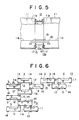
- Fig. 5 shows the structure of one of the connector members 12 in detail.
- Each connector member 12 comprises a bellows portion 12a, which is capable of being extended and contracted in the longitudinal direction thereof and of being bent by an appreciable amount along the same direction; further, each connector member 12 comprises a pair of flange portions 12b secured to the two ends of the bellows portion 12a.
- the flange portions 12b of the connector member 12 are fixedly secured, in a water-tight manner, to the circumferential portions of the opposing pair of connection openings 11a of two adjacent box members 11 by means of bolts 16 via packings 17, so as to prevent the intrusion of the rain water.
- the step plate 19 allows an easy passage of the inspection or maintenance personnel thereon through the connector member 12.
- an air-conditioning duct (not shown) may be disposed through each one of the connector members 12 to communicate the each pair of box members 11 connected by the connector members 12.
- Each one of the prefabricated box members 11 accomodating units of electrical equipment 3 has such exterior dimensions and weight as to allow its easy transportion.
- the necessary number of the respective box members 11 accomodating the electrical equipment, which are made and assembled in the factory, are transported to the substation site, together with the connector members 12, the support bases 7, and the steps 8; the doors 13 and 15 and the closure plates 14 may be fitted to the box members 11 before the transportation.
- the installation and assembly of the above housing structure on the substation site are effected as follows. First, the support bases 7 for the box members 11 are positioned and installed.
- the box members 11 are set on respective support bases 7, so as to align the opposing pairs of connection openings 11a with each other and to position adjacent box members at a predetermined distance from each other.
- the box members 11 are thereafter installed and fixedly secured on respective support bases 7.
- the connector members 12 are attached to the opposing pairs of connection openings 11a at the flange portions 12b thereof.
- the wiring ducts 18 are disposed at the bottom portion of the connector members 12 to extend therethrough, and step plates 19 are mounted over and above the wiring ducts 18.
- the extensible connector members 12 of a bellows structure allow for a substantial degree of freedom in the positional relationship between the two box members that are connected with each other therethrough; thus, the watertight connection between the box members 11 and the extensible connector members can be ensured without the high precision requirement being imposed on the positioning of the box members 11. As a result, the assembly can be effected easily in a short time with less labor.
- Fig. 6 shows another embodiment according to this invention.
- the number of box members 11 may be multiplied arbitrarily. Further, some of the box members 11 may be provided with six connection openings 11a instead of four. The unused openings 11a which are neither connected to the connector members 12 nor provided with entrance doors 13 are closed by closure plates 14 attached thereto.
- the unitary structure of the prefabricated box members 11 and the extensible bellows structure of the connector members 12 allow the configuration or the arrangement of the box members 11 and those of the entrance doors 13 to be chosen arbitrarily and adjusted and adapted to the particular needs of the substation; further, the multiplication of the number of box members 11 is easy.
- connection openings provided in each box member may be increased; further, although it is preferred that all the box members have the same unitary form to reduce the production cost thereof, some may be modified within the scope of the claimed structure when this is deemed desirable.
Landscapes
- Engineering & Computer Science (AREA)
- Power Engineering (AREA)
- Patch Boards (AREA)
- Casings For Electric Apparatus (AREA)
Claims (4)
- Structure de logement de type préfabriqué pour de l'équipement électrique de sous-station comprenant une pluralité d'éléments de boîtes préfabriqués (11) pour loger de l'équipement électrique de sous-station, chacun desdits éléments de boîtes ayant une forme rectangulaire en section transversale horizontale et étant pourvu d'ouvertures (11a) pour la connexion; des éléments de connexion extensibles (12) à structure en accordéon, chacun connectant une paire desdites ouvertures de connexion opposées de deux éléments de boîtes adjacents; une structure de porte (13) installée sur au moins une desdites ouvertures de connexion de la pluralité d'éléments de boîtes permettant au personnel de surveillance d'entrer dans ladite pluralité d'éléments de boîtes ou d'en sortir à travers cette structure; des plaques de fermeture (14) installées dans les ouvertures restantes dans desdites ouvertures de connexion des éléments de boîtes qui ne sont ni connectées auxdits éléments de connexion ni pourvues de la structure de porte; et des conduites pour conducteurs (18) s'étendant chacune à travers un desdits éléments de connexion dans une partie inférieure de celui-ci, des conducteurs qui connectent entre elles les unités dudit équipement électrique de sous-station logé dans ladite pluralité d'éléments de boîtes passant dans lesdites conduites pour conducteurs; caractérisée en ce que lesdits éléments de boîtes (11) ont au moins deux ouvertures de connexion (11a) sur chacune de leurs parois latérales ayant horizontalement une dimension plus importante que les deux autres parois latérales, lesdites ouvertures de connexion de chaque élément de boîte étant disposées l'une en regard de l'autre, dans les parois latérales se faisant face l'une l'autre.
- Structure de logement de type préfabriqué selon la revendication 1, dans laquelle ladite pluralité d'éléments de boîtes comprend des éléments de boîtes pourvus de six ouvertures de connexion.
- Structure de logement de type préfabriqué selon la revendication 1 ou 2, comprenant en outre des plaques de marches, chacune d'entre elles étant disposée au-dessus d'une conduite pour les conducteurs s'étendant à travers un élément de connexion pour former un passage à marches pour le personnel de surveillance à travers l'élément de connexion.
- Structure de logement de type préfabriqué selon la revendication 1 ou 2, dans laquelle une des deux dites ouvertures de connexion en regard connectées mutuellement par un élément de connexion est pourvue d'une porte.
Applications Claiming Priority (2)
| Application Number | Priority Date | Filing Date | Title |
|---|---|---|---|
| JP279656/88 | 1988-11-05 | ||
| JP63279656A JPH02131306A (ja) | 1988-11-05 | 1988-11-05 | 電気設備 |
Publications (2)
| Publication Number | Publication Date |
|---|---|
| EP0367975A1 EP0367975A1 (fr) | 1990-05-16 |
| EP0367975B1 true EP0367975B1 (fr) | 1993-11-03 |
Family
ID=17614024
Family Applications (1)
| Application Number | Title | Priority Date | Filing Date |
|---|---|---|---|
| EP19890118191 Expired - Lifetime EP0367975B1 (fr) | 1988-11-05 | 1989-09-30 | Structure de coffret préfabriqué pour sous-station |
Country Status (3)
| Country | Link |
|---|---|
| EP (1) | EP0367975B1 (fr) |
| JP (1) | JPH02131306A (fr) |
| CN (1) | CN1042809A (fr) |
Families Citing this family (3)
| Publication number | Priority date | Publication date | Assignee | Title |
|---|---|---|---|---|
| DE9217453U1 (de) * | 1992-12-21 | 1993-03-04 | Siemens AG, 8000 München | Kompensationseinrichtung |
| KR101380080B1 (ko) * | 2009-10-16 | 2014-04-01 | 후지쯔 가부시끼가이샤 | 케이블 덕트, 전자 장치 시스템, 케이블 덕트 시스템 및 전자 장치 시스템에 있어서의 하우징의 교환 방법 |
| CN110424447B (zh) * | 2019-08-27 | 2024-08-23 | 建华建材(中国)有限公司 | 一种装配式变电站一体化基础结构及其施工方法 |
Family Cites Families (1)
| Publication number | Priority date | Publication date | Assignee | Title |
|---|---|---|---|---|
| JPS63100903U (fr) * | 1986-12-16 | 1988-06-30 |
-
1988
- 1988-11-05 JP JP63279656A patent/JPH02131306A/ja active Pending
-
1989
- 1989-09-30 EP EP19890118191 patent/EP0367975B1/fr not_active Expired - Lifetime
- 1989-10-18 CN CN 89108119 patent/CN1042809A/zh active Pending
Also Published As
| Publication number | Publication date |
|---|---|
| CN1042809A (zh) | 1990-06-06 |
| JPH02131306A (ja) | 1990-05-21 |
| EP0367975A1 (fr) | 1990-05-16 |
Similar Documents
| Publication | Publication Date | Title |
|---|---|---|
| EP2567301A1 (fr) | Centre de données modulaire | |
| US4677524A (en) | Metalclad switchgear having separate assemblies | |
| US4494353A (en) | Method of manufacturing and building preformed modular building wall sections | |
| US2952799A (en) | Outdoor metal-clad switchgear | |
| EP0367975B1 (fr) | Structure de coffret préfabriqué pour sous-station | |
| EP0459593B1 (fr) | Module à compartiments pour un système de distribution moyenne tension modulaire à enceinte métallique, et système de distribution assemblé avec ces modules | |
| EP0271830B1 (fr) | Installation pour équipement électrique | |
| EP0055094B1 (fr) | Sous-stations à isolation gazeuse | |
| CN106972391A (zh) | 一种预装式变电站 | |
| EP1970502A1 (fr) | Poste secondaire compact modulaire | |
| EP0863267A2 (fr) | Unité d'habitation et construction du cadre de l'unité d'habitation | |
| US3281998A (en) | Self-sustaining collapsible building structure | |
| JP2598256Y2 (ja) | 配電盤用枠組体および配電盤 | |
| JP2024085762A (ja) | 電気所の受変電設備及びその建設方法 | |
| CN115492433A (zh) | 一种预制舱电气设备模块、预制舱及变电站 | |
| CN115492434A (zh) | 一种变压器外置的变电站 | |
| CN219419989U (zh) | 一种方便组合的变电箱壳体 | |
| JP2565745Y2 (ja) | 閉鎖配電盤 | |
| DE2941382A1 (de) | Elektrisches schalthaus aus vorgefertigten beton-raumzellen | |
| CN115506637B (zh) | 一种变压器内置的变电站 | |
| CN215330711U (zh) | 一种集成家庭电气控制中心的组合墙体 | |
| JP2908068B2 (ja) | ガス絶縁受電設備 | |
| CN119627677A (zh) | 快捷双电源模块化顶置集中散热紧凑型预制舱式变电站 | |
| CN1765038B (zh) | 开关设备及其框体 | |
| JPH0540673Y2 (fr) |
Legal Events
| Date | Code | Title | Description |
|---|---|---|---|
| PUAI | Public reference made under article 153(3) epc to a published international application that has entered the european phase |
Free format text: ORIGINAL CODE: 0009012 |
|
| 17P | Request for examination filed |
Effective date: 19890930 |
|
| AK | Designated contracting states |
Kind code of ref document: A1 Designated state(s): BE CH FR LI |
|
| 17Q | First examination report despatched |
Effective date: 19920617 |
|
| GRAA | (expected) grant |
Free format text: ORIGINAL CODE: 0009210 |
|
| AK | Designated contracting states |
Kind code of ref document: B1 Designated state(s): BE CH FR LI |
|
| ET | Fr: translation filed | ||
| PLBE | No opposition filed within time limit |
Free format text: ORIGINAL CODE: 0009261 |
|
| STAA | Information on the status of an ep patent application or granted ep patent |
Free format text: STATUS: NO OPPOSITION FILED WITHIN TIME LIMIT |
|
| 26N | No opposition filed | ||
| PGFP | Annual fee paid to national office [announced via postgrant information from national office to epo] |
Ref country code: FR Payment date: 19960910 Year of fee payment: 8 |
|
| PGFP | Annual fee paid to national office [announced via postgrant information from national office to epo] |
Ref country code: CH Payment date: 19961004 Year of fee payment: 8 |
|
| PGFP | Annual fee paid to national office [announced via postgrant information from national office to epo] |
Ref country code: BE Payment date: 19961118 Year of fee payment: 8 |
|
| PG25 | Lapsed in a contracting state [announced via postgrant information from national office to epo] |
Ref country code: LI Free format text: LAPSE BECAUSE OF NON-PAYMENT OF DUE FEES Effective date: 19970930 Ref country code: FR Free format text: THE PATENT HAS BEEN ANNULLED BY A DECISION OF A NATIONAL AUTHORITY Effective date: 19970930 Ref country code: CH Free format text: LAPSE BECAUSE OF NON-PAYMENT OF DUE FEES Effective date: 19970930 Ref country code: BE Free format text: LAPSE BECAUSE OF NON-PAYMENT OF DUE FEES Effective date: 19970930 |
|
| BERE | Be: lapsed |
Owner name: MITSUBISHI DENKI K.K. Effective date: 19970930 |
|
| REG | Reference to a national code |
Ref country code: CH Ref legal event code: PL |
|
| REG | Reference to a national code |
Ref country code: FR Ref legal event code: ST |