EP0367992A2 - Rouleau pour travail de sol - Google Patents
Rouleau pour travail de sol Download PDFInfo
- Publication number
- EP0367992A2 EP0367992A2 EP89118481A EP89118481A EP0367992A2 EP 0367992 A2 EP0367992 A2 EP 0367992A2 EP 89118481 A EP89118481 A EP 89118481A EP 89118481 A EP89118481 A EP 89118481A EP 0367992 A2 EP0367992 A2 EP 0367992A2
- Authority
- EP
- European Patent Office
- Prior art keywords
- roller according
- field roller
- tire
- rim
- rim elements
- Prior art date
- Legal status (The legal status is an assumption and is not a legal conclusion. Google has not performed a legal analysis and makes no representation as to the accuracy of the status listed.)
- Withdrawn
Links
- 239000011324 bead Substances 0.000 claims description 20
- 238000013459 approach Methods 0.000 claims description 14
- 238000004140 cleaning Methods 0.000 claims description 4
- 241001131688 Coracias garrulus Species 0.000 abstract 2
- 239000002689 soil Substances 0.000 description 17
- 238000013461 design Methods 0.000 description 10
- 230000008901 benefit Effects 0.000 description 5
- 230000002349 favourable effect Effects 0.000 description 5
- 238000004519 manufacturing process Methods 0.000 description 4
- 238000000034 method Methods 0.000 description 3
- 230000004048 modification Effects 0.000 description 3
- 238000012986 modification Methods 0.000 description 3
- 230000008569 process Effects 0.000 description 3
- 238000005096 rolling process Methods 0.000 description 3
- 230000004323 axial length Effects 0.000 description 2
- 238000003860 storage Methods 0.000 description 2
- 238000003971 tillage Methods 0.000 description 2
- 230000007704 transition Effects 0.000 description 2
- 238000003466 welding Methods 0.000 description 2
- 230000015572 biosynthetic process Effects 0.000 description 1
- 238000007596 consolidation process Methods 0.000 description 1
- 238000010276 construction Methods 0.000 description 1
- 239000000356 contaminant Substances 0.000 description 1
- 238000011109 contamination Methods 0.000 description 1
- 238000011161 development Methods 0.000 description 1
- 230000018109 developmental process Effects 0.000 description 1
- 238000005187 foaming Methods 0.000 description 1
- 238000009434 installation Methods 0.000 description 1
- 239000000463 material Substances 0.000 description 1
- 239000002184 metal Substances 0.000 description 1
- 230000035515 penetration Effects 0.000 description 1
- 230000036316 preload Effects 0.000 description 1
- 230000009467 reduction Effects 0.000 description 1
- 230000008719 thickening Effects 0.000 description 1
Images

Classifications
-
- A—HUMAN NECESSITIES
- A01—AGRICULTURE; FORESTRY; ANIMAL HUSBANDRY; HUNTING; TRAPPING; FISHING
- A01B—SOIL WORKING IN AGRICULTURE OR FORESTRY; PARTS, DETAILS, OR ACCESSORIES OF AGRICULTURAL MACHINES OR IMPLEMENTS, IN GENERAL
- A01B29/00—Rollers
- A01B29/04—Rollers with non-smooth surface formed of rotatably-mounted rings or discs or with projections or ribs on the roller body; Land packers
- A01B29/041—Rollers with non-smooth surface formed of rotatably-mounted rings or discs or with projections or ribs on the roller body; Land packers of "Cambridge"-type, i.e. the soil-pressing rings being stacked on a shaft
- A01B29/043—Tyre-packers
Definitions
- the invention relates to a field roller with several tires arranged side by side.
- a variety of forms of field rollers are known from the prior art, which comprise a plurality of tires arranged next to one another, which roll on the field soil.
- the tires are usually in the form of vehicle rubber tires, such a roller is known for example from GB-PS 739 871 and EP-A1-223 134.
- a roller is known for example from GB-PS 739 871 and EP-A1-223 134.
- Another disadvantage of such a roller is the fact that soil or the like can penetrate into the spaces between adjacent wheels, so that additional measures, for example cover rings, must be provided.
- EP-A2-160 612 shows a field roller which is designed in the form of a tooth roller. Tires are arranged in the spaces between the essentially disk-shaped tooth arrangements, which can perform a flexing movement in order to repel adhering soil in this way.
- DE-OS 23 17 969 which forms the closest prior art, shows a field roller with several tires arranged side by side, which are spaced in the axial direction and thus also raise the problem that lumps of earth, stones or the like in the spaces between the Tire can penetrate.
- the tires themselves are in the form of low-pressure tires.
- the invention has for its object to provide a field roller of the type mentioned, which with a simple structure and reliable mode of operation enables a uniform and level cultivation of the soil and in which an adhesion of soil or the like is prevented.
- the object is achieved in that a plurality of annular rim elements are provided which are arranged next to one another to form an essentially cylindrical roller body and which carry a plurality of low-pressure, low-profile tires.
- the field roller according to the invention is characterized by a number of considerable advantages.
- the unpressurized low-profile tires can walk very strongly when rolling on the ground, so that the adherence of soil, in particular of moist soil, is prevented, since this falls off from the surface of the low-profile tire due to the deformation thereof.
- the invention creates the possibility of deforming the tires to a large extent due to their design as non-pressurized low-profile tires.
- ring-shaped rim elements makes it possible to form a substantially cylindrical roller body which, in the area of its contact surface, ie in the area in which the low-profile tires are deformed, has a cylindrical, metallic shape and mode of operation Corresponds to the roller, on the outer surface of which a rubber layer of the same thickness is arranged.
- the tires in the field rollers known from the prior art due to the strength of the flank areas of the tires and the transition areas from the tread to the flanks and the resulting undefined rolling radius, lead to vibrations and uneven rolling of the field roller or one uneven draft of the devices coupled to the roller.
- Another important advantage of the invention results from the fact that the low-pressure, low-profile tires in the area of the footprint of the tire can be deformed in such a way that a flat, groove-free floor surface can be achieved.
- the tire comprises a tread and two shoulder areas connected to one another and that each shoulder area is supported on a rim element.
- the rim elements are therefore not configured in the form of conventional rims which support the two shoulder areas of an individual tire, rather each rim element serves to support one shoulder area of two adjacent tires.
- this measure enables a particularly simple design and manufacture of the rim element, on the other hand, the possibility is created to design the intermediate area between adjacent tires in such a way that the penetration of soil, stones or parts of plants is avoided. Since there is no free gap or gap between adjacent tires in the area of the rim elements space is available, it is possible. to dispense with additional wiping elements or the like.
- first rim elements are arranged in the central area of the field roller, which have two contact shoulders for adjacent tires, and that a second rim element, each with an contact shoulder, is arranged at the two ends.
- the respective end region of the field roller can in particular be configured such that the outermost tire is flush with the side surface of the field roller.
- the contact shoulders of the first rim element adjoin one another axially.
- the space between adjacent tires is minimized, so that the field roller lies completely on the rubber material of the tires in the contact area.
- the contact shoulders of the first rim element are connected axially by means of an essentially cylindrical spacing area.
- the distance range can also be formed radially set back. In the latter embodiment, it is possible to reduce the pressure on the ground in the areas between the tires. If the distance range che are not set back, they can also serve as support surfaces.
- the shoulder regions of the tire can be designed such that they have an obtuse angle or an angle of 180 ° to one another.
- a wide variety of configurations of the tires are possible, but in particular they should each have the lowest possible shoulder or flank areas.
- the contact shoulders of adjacent rim elements are axially spaced apart by a substantially cylindrical intermediate area in the central area of the tire.
- the intermediate region can either be designed in the form of lateral cylindrical projections of the rim element or can be formed by a separate cylinder ring.
- the tire is provided with at least one web area connected to a tread and extending in the radial direction, the radially lying end area of which is widened by means of lateral beads.
- the end area is supported by the rim elements.
- a particularly favorable storage of the tire is provided if the rim elements at least partially encompass the beads. Furthermore, it can prove to be advantageous to provide the tire with a central land area or to form a land area laterally adjacent to the tread.
- the number of land areas depends on the overall width of the tire and can be adapted to the respective requirements in a particularly simple manner. Instead of a very wide central land area, it is thus possible to provide two separate land areas on the side edges of the tread in order to increase the tipping resistance of the tire.
- the tire is provided in the area of the treads with elastic annular beads directed radially and / or axially away from the center of the tire.
- the ring beads can be designed such that their shape, in particular the cross-sectional shape, changes greatly between the loaded and the unloaded state. Through these deformation processes, clumps of earth and the like adhering to the tires are blasted off, so that the roller has a high degree of self-cleaning power.
- a cavity of the tire can also be dispensed with in this embodiment, since the respective surface or tread regions have sufficient deformation and inherent elasticity. This shape of the tire tread is therefore particularly inexpensive and easy to manufacture and still requires only one low installation effort.
- the additional advantage is that it is not necessary to set or control tire pressures or the like, so that the field roller built up from the tires is very reliable and has a long service life.
- the ring beads delimit a concave tread area in the unloaded state of the tire and form a tread area in the loaded state of the tire, which can either be flat or crowned. This ensures sufficient consolidation of the soil on the one hand, and on the other hand the flexing movement of the tire causes it to repel the clumps of earth or the like adhering to the surface in order to avoid contamination of the field roller or clogging with soil.
- rim elements In order to assign the rim elements to one another to form the essentially cylindrical roller body, these can be pushed onto a cylindrical support body.
- the cylindrical support body can be designed in the form of a simple cylinder tube. Since the support body gives the entire field roller sufficient strength, it is not necessary in this embodiment that the rim elements are designed in the form of closed rings, rather they can also be produced as half rings. Depending on the design of the rim elements, this simplifies production and leads to a considerable reduction in costs.
- the rim elements can include lugs that can be brought into engagement with one another in a form-fitting manner, ie the rim rings can be inserted into each other laterally to form a cylindrical roller body.
- the side lugs which overlap or overlap each other, ensure a firm hold of the rim elements against each other.
- the rim elements can be carried by means of a plurality of tensioned holding rods arranged spaced apart on the inner circumference.
- a plurality of tensioned holding rods arranged spaced apart on the inner circumference.
- the rim elements are preferably arranged on the support body in such a way that a relative movement between the individual rim elements and between the rim elements and the support body is prevented.
- a foaming mass which is arranged in an intermediate space between the rim elements and the support body, it is possible to ensure a secure fit of the rim elements or rings on the support body and to compensate for manufacturing tolerances that occur in this way.
- Another possibility is to fill the space between the rim elements and / or the support body with a curable elastic mass, which can be applied during assembly, for example, and subsequently cured.
- Another possibility is to connect the rims of the rim elements to the support body, for example by welding.
- This embodiment is particularly well suited for a field roller in which several rim elements or rings are braced against one another by means of several long tensioning screws.
- Another possibility according to the invention is to design the approaches of adjacent rim elements each with a different diameter, so that one approach can be plugged onto the other approach. It is in particular possible to design at least one of the lugs to be spreadable in the radial direction, so that when the individual rim elements are pushed together or clamped, the respective lugs are pressed against one another and are thus wedged against one another.
- the disks can be provided with mounting recesses in addition to corresponding recesses for the passage of the screw bolts.
- the mounting recesses can, for example, have a larger diameter than the recesses for the passage of the screw bolts.
- an additional scraper can be arranged in the area of the outer circumference of the field roller.
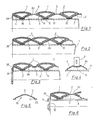
- a first embodiment of the field roller according to the invention is shown schematically in the sectional view.
- the field roller comprises a cylindrical support body 7, which is designed, for example, in the form of a cylinder tube.
- a cylindrical support body 7 which is designed, for example, in the form of a cylinder tube.
- the figures do not show the axis, the lateral support arms and the bearings of the field roller in detail. These components can be designed in the usual way.
- a plurality of rim elements 3a, 3b are arranged on the support body 7, each of which carries unpressurized low-profile tires 1.
- the tires 1 have a very flat cross section and have no internal pressure, so that the tread is subjected to a strong flexing movement when it rolls.
- the shoulder regions 2 of the tires 1 are arranged at an obtuse angle to one another and are connected centrally by a foot region 10. When the tire rests on the ground, it is deformed to such an extent that an essentially flat contact surface results.
- the rim element 3 a has a cylindrical spacing area 5, which is provided on both sides in one piece with an abutment shoulder 4.
- the contact shoulders 4 have an obtuse angle to one another, which corresponds to the angle of the shoulder regions 2 of the tires 1.
- the contact edges 11 lie on the surface of the support body 7.
- the lateral distance between adjacent rim elements is formed by means of an intermediate area 6, which. as shown in Fig. 1, can be designed in the form of an annular element.
- the second rim elements 3b form the lateral end elements and are each only equipped with an abutment shoulder 4 which, as in the first rim elements 3a, merges into an abutting edge 11.
- the other side of the second rim element 3b is formed by an annular disk extending in the axial direction.
- FIG. 2 shows a further exemplary embodiment of the invention, which differs from the exemplary embodiment shown in FIG. 1 in that the rim elements 3a do not comprise a distance area 5, but rather their abutment shoulders 4 directly adjoin one another.
- FIG. 3 shows a further modification of the exemplary embodiment shown in FIG. 1, according to which the distance region 5 is set back inwards in the radial direction.
- a side wall 12 is shown in FIG. 4, which can be designed, for example, in the form of a circular disk to which the support body 7 is connected.
- the side wall 12 has a recess through which an axis can be passed in order to support the field roller on lateral support arms and to brace the axis in its longitudinal direction so that the side walls 12 are pulled towards one another.
- FIG. 4 shows a single rim element of the exemplary embodiment shown in FIG. 3, to which a scraper 9 is assigned in order to clean the recessed spacing area 5 from adhering soil.
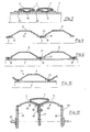
- FIG. 5 another embodiment of a rim member is shown in section, which differs from the previously shown embodiments in that adjacent to the contact edge 11 is provided an extension 13 which has an axial length which is half the axial length of the intermediate range 6 corresponds. It is thus possible to arrange the rim elements 3a or the appropriately designed rim element 3b adjacent to one another without additional intermediate elements, as is shown in FIG. 6.
- the embodiment of the field roller according to the invention shown in FIG. 6 has, instead of the cylindrical support body 7, a plurality of holding rods 8, which are arranged on the inside of the rim elements and are evenly distributed around the circumference.
- the holding rods 8 can each be provided with a thread at their ends and clamped to the side walls 12 by means of a nut 14.
- FIG. 7 shows a further embodiment of the field roller according to the invention, which differs from the previously described embodiments in that the shoulder regions 2 of the tires 1 form an angle of 180 °.
- the rim elements 3a can be designed in a particularly simple manner in the form of cylindrical rings. Lateral slipping of the tires is prevented by the fact that their foot region 10 is inserted into spaces between adjacent rim elements 3.
- a plurality of support bodies 7 are provided, each of which is designed in the form of cylindrical rings and is connected to a shoulder 13 of a rim element by means of a weld seam 16.
- FIG. 9 shows a further exemplary embodiment, in which the lugs 13 are each chamfered on their outer edges, so that an annular elastic body 15 can be arranged between the lugs and the support body 7.
- annular elastic body 15 By using this ring body 15, the space between the lugs 13 and the support body 7, which is shown exaggeratedly large in Fig. 9 for the purpose of clarity, can be bridged, so that no relative movement between the rim elements 3a, 3b and the cylindrical support body 7 occurs.
- At least one of the lugs 13 is designed with a diameter which differs from the diameter of the other lug 13, so that adjoining lugs of adjacent rim elements 3a, 3b can be pushed onto one another. It proves to be particularly advantageous to provide at least one of the lugs 13 with axial slots, so that this can be spread or reduced in diameter. This makes it possible to firmly clamp or wedge the rim elements to the support body 7 by lateral clamping.
- FIG. 11 shows a further exemplary embodiment of the field roller according to the invention, in which adjacent rim elements 3a are each connected to side disks 17, 18, for example by means of a Welding process.
- the respective disks 17, 18 of adjacent rim elements 3a can be connected to one another via screw bolts 19.
- the disks 17, 18 each have mounting recesses which are dimensioned in a corresponding manner. According to the invention, it is thus possible to connect the rim elements themselves and additionally to preload a central axis 21.
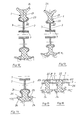
- the tire 1 has a web region 21 which extends in the radial direction and is provided with lateral beads 23 at its radially inner end region 22.
- the lateral beads 23 thus represent an axial widening or thickening of the end region 22 and can be gripped or clasped laterally by the rim elements 3.
- the tires 1 At the radially outer areas, the tires 1 have obliquely outwardly directed annular beads 24 which are elastic and which, in the unloaded state shown in FIGS.
- the elastic annular beads 24 are deformed such that, as shown in the lower halves of FIGS. 12 and 13, the tire 1 has a substantially flat (FIG. 12) or concave (FIG. 13) contact surface or tread . So it becomes, for example Bottom groove formed with an almost flat bottom (Fig. 12). However, it is also possible, as shown in FIG. 13, to form a floor channel with two lowered areas.
- the configuration of the annular beads (24) can be varied over a wide range and adapted to the respective requirements.
- FIGS. 12 and 13 show a further modification of the exemplary embodiments shown in FIGS. 12 and 13, in which the rim elements 3 are provided with shoulders 25 at the radially outer ends, which should also serve to support the annular beads 24 by the radius of the roller to be followed more precisely in the loaded state.
- the two annular beads 24 and the shoulders 25 form a spherical bearing surface under load.
- 15 and 16 show different embodiments in which the support body 7 has a larger diameter, so that the end regions 22 of the tires can be placed directly against the support body 7.
- the central web regions 21 of the tires 1 each have a thickness which leads to sufficient rigidity of the tires and eliminates the risk of buckling.
- FIG. 17 and 18 show alternative embodiments of the tire according to the invention, which to both Sides of the tread are each provided with a web area 21, the end area 22 of which, as already described, carries lateral beads 23 which can be clamped by means of the rim elements 3.
- FIG. 17 shows an embodiment in which four rim elements 3 are provided for each tire 1.
- the rim elements can also be designed so that they support the tire from the inside.
- the rim elements 3 shown in FIG. 17 are each of the same design, but it is also possible, as shown in FIG. 19, to use symmetrical rim elements 3, one such rim element being in one tire, while the next tire element is between two adjacent tires is arranged.
- a plurality of cylindrical rim elements 3 are pushed onto the tubular support body 7, the respective web area 21 being supported directly against the support body 7.
- ribs 27 are provided on the outer circumference, which, when the field roller rolls, produce grooves in the surface of the earth in which seed can be deposited.
- tires 1 or the rim elements 3 can be rotatably arranged on the support body 7, so that cornering of the field roller, for example when turning or when the field edges are not straight, are made considerably easier.
Landscapes
- Life Sciences & Earth Sciences (AREA)
- Engineering & Computer Science (AREA)
- Mechanical Engineering (AREA)
- Soil Sciences (AREA)
- Environmental Sciences (AREA)
- Tires In General (AREA)
- Soil Working Implements (AREA)
Applications Claiming Priority (2)
| Application Number | Priority Date | Filing Date | Title |
|---|---|---|---|
| DE8814135U DE8814135U1 (de) | 1988-11-11 | 1988-11-11 | Ackerwalze |
| DE8814135U | 1988-11-11 |
Publications (2)
| Publication Number | Publication Date |
|---|---|
| EP0367992A2 true EP0367992A2 (fr) | 1990-05-16 |
| EP0367992A3 EP0367992A3 (fr) | 1990-09-12 |
Family
ID=6829778
Family Applications (1)
| Application Number | Title | Priority Date | Filing Date |
|---|---|---|---|
| EP19890118481 Withdrawn EP0367992A3 (fr) | 1988-11-11 | 1989-10-05 | Rouleau pour travail de sol |
Country Status (2)
| Country | Link |
|---|---|
| EP (1) | EP0367992A3 (fr) |
| DE (1) | DE8814135U1 (fr) |
Cited By (9)
| Publication number | Priority date | Publication date | Assignee | Title |
|---|---|---|---|---|
| EP0401592A1 (fr) * | 1989-06-08 | 1990-12-12 | Amazonen-Werke H. Dreyer GmbH & Co. KG | Rouleau agricole |
| FR2694864A1 (fr) * | 1992-08-20 | 1994-02-25 | Herriau Auguste | Rouleau tasseur à pneumatiques multiples pour le travail des sols. |
| FR2694863A1 (fr) * | 1992-08-20 | 1994-02-25 | Herriau Auguste | Rouleau tasseur à pneumatiques multiples pour le travail des sols. |
| EP0682854A1 (fr) * | 1994-05-17 | 1995-11-22 | Kuhn S.A. | Rouleau de travail du sol à usage agricole et machine agricole utilisant un tel rouleau |
| EP0861577A3 (fr) * | 1997-02-21 | 1998-09-30 | Amazonen-Werke H. Dreyer GmbH & Co. KG | Rouleau pour sol |
| FR2776239A1 (fr) * | 1998-03-18 | 1999-09-24 | Otico | Pneumatique a usages speciaux, en particulier pour materiels agricoles |
| FR2784331A1 (fr) * | 1998-10-13 | 2000-04-14 | Otico | Dispositif d'assemblage pour des pneumatiques du type semi-creux |
| FR2789940A1 (fr) * | 1999-02-23 | 2000-08-25 | Otico | Pneumatique du type semi-creux de structure renforcee |
| WO2005122742A1 (fr) * | 2004-06-16 | 2005-12-29 | Simba International Ltd | Appareil de traitement du sol |
Families Citing this family (2)
| Publication number | Priority date | Publication date | Assignee | Title |
|---|---|---|---|---|
| DE10331233A1 (de) * | 2003-07-10 | 2005-02-03 | Rabe Agrarsysteme Gmbh & Co. Kg | Bodenwalze |
| DE102006022536A1 (de) * | 2006-05-15 | 2007-11-22 | Amazonen-Werke H. Dreyer Gmbh & Co. Kg | Landwirtschaftliche Bodenwalze |
Family Cites Families (9)
| Publication number | Priority date | Publication date | Assignee | Title |
|---|---|---|---|---|
| FR637271A (fr) * | 1926-11-05 | 1928-04-26 | Perfectionnements aux roues à jante métallique | |
| GB739871A (en) * | 1953-04-08 | 1955-11-02 | Odd Floden | A road or like roller |
| DE1038810B (de) * | 1955-10-12 | 1958-09-11 | Continental Gummi Werke Ag | Tast- oder Fuehrungsrad fuer land-wirtschaftliche Bodenbearbeitungsgeraete |
| FR1348608A (fr) * | 1962-12-01 | 1964-01-10 | Metalastik Ltd | Roue élastique |
| FR2347863A1 (fr) * | 1976-04-12 | 1977-11-10 | Pello Andre | Rouleau agricole |
| DE3034571A1 (de) * | 1980-09-11 | 1982-05-06 | Howard Machinery Ltd., Bury St. Edmunds, Suffolk | Selbstreinigende krumenpackerwalze |
| EP0160612B1 (fr) * | 1984-05-02 | 1989-10-11 | Kuhn S.A. | Machine agricole de travail du sol perfectionnée |
| DE8519861U1 (de) * | 1985-07-10 | 1985-09-05 | Rabewerk Heinrich Clausing, 4515 Bad Essen | Bodenwalze für die Bodenbearbeitung in der Landwirtschaft |
| DE3539821A1 (de) * | 1985-11-09 | 1987-05-14 | Amazonen Werke Dreyer H | Bodenwalze |
-
1988
- 1988-11-11 DE DE8814135U patent/DE8814135U1/de not_active Expired
-
1989
- 1989-10-05 EP EP19890118481 patent/EP0367992A3/fr not_active Withdrawn
Cited By (11)
| Publication number | Priority date | Publication date | Assignee | Title |
|---|---|---|---|---|
| EP0401592A1 (fr) * | 1989-06-08 | 1990-12-12 | Amazonen-Werke H. Dreyer GmbH & Co. KG | Rouleau agricole |
| FR2694864A1 (fr) * | 1992-08-20 | 1994-02-25 | Herriau Auguste | Rouleau tasseur à pneumatiques multiples pour le travail des sols. |
| FR2694863A1 (fr) * | 1992-08-20 | 1994-02-25 | Herriau Auguste | Rouleau tasseur à pneumatiques multiples pour le travail des sols. |
| EP0682854A1 (fr) * | 1994-05-17 | 1995-11-22 | Kuhn S.A. | Rouleau de travail du sol à usage agricole et machine agricole utilisant un tel rouleau |
| FR2719969A1 (fr) * | 1994-05-17 | 1995-11-24 | Kuhn Sa | Rouleau de travail du sol à usage agricole et machine agricole utilisant un tel rouleau. |
| EP0861577A3 (fr) * | 1997-02-21 | 1998-09-30 | Amazonen-Werke H. Dreyer GmbH & Co. KG | Rouleau pour sol |
| FR2776239A1 (fr) * | 1998-03-18 | 1999-09-24 | Otico | Pneumatique a usages speciaux, en particulier pour materiels agricoles |
| FR2784331A1 (fr) * | 1998-10-13 | 2000-04-14 | Otico | Dispositif d'assemblage pour des pneumatiques du type semi-creux |
| FR2789940A1 (fr) * | 1999-02-23 | 2000-08-25 | Otico | Pneumatique du type semi-creux de structure renforcee |
| EP1033266A1 (fr) * | 1999-02-23 | 2000-09-06 | Otico | Pneumatique du type semi-creux de structure renforcée |
| WO2005122742A1 (fr) * | 2004-06-16 | 2005-12-29 | Simba International Ltd | Appareil de traitement du sol |
Also Published As
| Publication number | Publication date |
|---|---|
| DE8814135U1 (de) | 1989-01-26 |
| EP0367992A3 (fr) | 1990-09-12 |
Similar Documents
| Publication | Publication Date | Title |
|---|---|---|
| DE19745409C2 (de) | Fahrzeugrad mit einem Notlaufstützkörper | |
| DE19833436B4 (de) | Nabeneinheit-Komplettlager und Verfahren zur Herstellung desselben | |
| WO1999064260A1 (fr) | Roue de vehicule automobile comportant un corps d'appui pour roulement de secours | |
| EP2976545A1 (fr) | Procédé de fabrication d'un palier et palier | |
| EP0367992A2 (fr) | Rouleau pour travail de sol | |
| DE2655189A1 (de) | Rad mit radkappe | |
| WO2007003591A1 (fr) | Roue de vehicule sur rails a suspension elastique en caoutchouc | |
| DE69807570T2 (de) | Halbhohlreifen und Walze mit solchen Reifen | |
| DE3111566A1 (de) | Luftreifenanordnung | |
| EP1431077A1 (fr) | Pneumatique pour véhicules | |
| WO2014023598A1 (fr) | Structure de roue d'une automobile | |
| DE2906734C3 (de) | Laufrolle in Zwillingsradanordnung | |
| EP0379672A1 (fr) | Rouleau de travail du sol | |
| EP1117944A1 (fr) | Palier metallo-caoutchoute a amortissement axial | |
| DE69501793T2 (de) | Rad | |
| DE102021202509A1 (de) | Steer-by-Wire-Lenksystem | |
| DE2339516A1 (de) | Auf eine felge aufziehbarer luftreifen mit plattfahr-eigenschaften | |
| DE602004012697T2 (de) | Optimierte Felge und Rad mit solcher Felge | |
| DE9205660U1 (de) | Bodenwalze | |
| WO2016066289A1 (fr) | Roue ferroviaire et véhicule ferroviaire | |
| DE1034421B (de) | Elastisches Gelenk | |
| DE2803134A1 (de) | Bereifung fuer mehrfach bereifte fahrzeuge | |
| DE102017002727A1 (de) | Vorrichtung und Verfahren zum Walzen von insbesondere Ackerböden o. dgl. Nutzflächen | |
| EP1619045A2 (fr) | Ecrou de roue pour fixation de roues de véhicules | |
| EP0061136A1 (fr) | Dispositif de pontage de l'espacement entre des pneumatiques jumelés |
Legal Events
| Date | Code | Title | Description |
|---|---|---|---|
| PUAI | Public reference made under article 153(3) epc to a published international application that has entered the european phase |
Free format text: ORIGINAL CODE: 0009012 |
|
| AK | Designated contracting states |
Kind code of ref document: A2 Designated state(s): DE FR GB NL |
|
| RAP1 | Party data changed (applicant data changed or rights of an application transferred) |
Owner name: RABEWERK GMBH + CO. |
|
| PUAL | Search report despatched |
Free format text: ORIGINAL CODE: 0009013 |
|
| AK | Designated contracting states |
Kind code of ref document: A3 Designated state(s): DE FR GB NL |
|
| 17P | Request for examination filed |
Effective date: 19901217 |
|
| 17Q | First examination report despatched |
Effective date: 19920205 |
|
| STAA | Information on the status of an ep patent application or granted ep patent |
Free format text: STATUS: THE APPLICATION HAS BEEN WITHDRAWN |
|
| 18W | Application withdrawn |
Withdrawal date: 19920605 |