EP0368012A2 - Verfahren und Vorrichtung zur Steuerung einer Wachspritzanlage - Google Patents
Verfahren und Vorrichtung zur Steuerung einer Wachspritzanlage Download PDFInfo
- Publication number
- EP0368012A2 EP0368012A2 EP89118866A EP89118866A EP0368012A2 EP 0368012 A2 EP0368012 A2 EP 0368012A2 EP 89118866 A EP89118866 A EP 89118866A EP 89118866 A EP89118866 A EP 89118866A EP 0368012 A2 EP0368012 A2 EP 0368012A2
- Authority
- EP
- European Patent Office
- Prior art keywords
- wax
- rubber mold
- coding
- spraying system
- assigned
- Prior art date
- Legal status (The legal status is an assumption and is not a legal conclusion. Google has not performed a legal analysis and makes no representation as to the accuracy of the status listed.)
- Granted
Links
- 238000000034 method Methods 0.000 title claims description 6
- 238000000465 moulding Methods 0.000 title 1
- 238000005507 spraying Methods 0.000 claims abstract description 31
- 238000002347 injection Methods 0.000 claims abstract description 20
- 239000007924 injection Substances 0.000 claims abstract description 20
- PCHJSUWPFVWCPO-UHFFFAOYSA-N gold Chemical group [Au] PCHJSUWPFVWCPO-UHFFFAOYSA-N 0.000 description 3
- 239000007921 spray Substances 0.000 description 3
- 238000005266 casting Methods 0.000 description 2
- 239000010931 gold Substances 0.000 description 2
- 229910052737 gold Inorganic materials 0.000 description 2
- 238000004519 manufacturing process Methods 0.000 description 2
- 230000004913 activation Effects 0.000 description 1
- 238000001816 cooling Methods 0.000 description 1
- 230000001627 detrimental effect Effects 0.000 description 1
Images


Classifications
-
- B—PERFORMING OPERATIONS; TRANSPORTING
- B29—WORKING OF PLASTICS; WORKING OF SUBSTANCES IN A PLASTIC STATE IN GENERAL
- B29C—SHAPING OR JOINING OF PLASTICS; SHAPING OF MATERIAL IN A PLASTIC STATE, NOT OTHERWISE PROVIDED FOR; AFTER-TREATMENT OF THE SHAPED PRODUCTS, e.g. REPAIRING
- B29C45/00—Injection moulding, i.e. forcing the required volume of moulding material through a nozzle into a closed mould; Apparatus therefor
- B29C45/17—Component parts, details or accessories; Auxiliary operations
- B29C45/76—Measuring, controlling or regulating
-
- B—PERFORMING OPERATIONS; TRANSPORTING
- B29—WORKING OF PLASTICS; WORKING OF SUBSTANCES IN A PLASTIC STATE IN GENERAL
- B29C—SHAPING OR JOINING OF PLASTICS; SHAPING OF MATERIAL IN A PLASTIC STATE, NOT OTHERWISE PROVIDED FOR; AFTER-TREATMENT OF THE SHAPED PRODUCTS, e.g. REPAIRING
- B29C37/00—Component parts, details, accessories or auxiliary operations, not covered by group B29C33/00 or B29C35/00
-
- B—PERFORMING OPERATIONS; TRANSPORTING
- B29—WORKING OF PLASTICS; WORKING OF SUBSTANCES IN A PLASTIC STATE IN GENERAL
- B29C—SHAPING OR JOINING OF PLASTICS; SHAPING OF MATERIAL IN A PLASTIC STATE, NOT OTHERWISE PROVIDED FOR; AFTER-TREATMENT OF THE SHAPED PRODUCTS, e.g. REPAIRING
- B29C67/00—Shaping techniques not covered by groups B29C39/00 - B29C65/00, B29C70/00 or B29C73/00
- B29C67/24—Shaping techniques not covered by groups B29C39/00 - B29C65/00, B29C70/00 or B29C73/00 characterised by the choice of material
- B29C67/241—Moulding wax
-
- B—PERFORMING OPERATIONS; TRANSPORTING
- B29—WORKING OF PLASTICS; WORKING OF SUBSTANCES IN A PLASTIC STATE IN GENERAL
- B29C—SHAPING OR JOINING OF PLASTICS; SHAPING OF MATERIAL IN A PLASTIC STATE, NOT OTHERWISE PROVIDED FOR; AFTER-TREATMENT OF THE SHAPED PRODUCTS, e.g. REPAIRING
- B29C37/00—Component parts, details, accessories or auxiliary operations, not covered by group B29C33/00 or B29C35/00
- B29C2037/80—Identifying, e.g. coding, dating, marking, numbering
-
- B—PERFORMING OPERATIONS; TRANSPORTING
- B29—WORKING OF PLASTICS; WORKING OF SUBSTANCES IN A PLASTIC STATE IN GENERAL
- B29C—SHAPING OR JOINING OF PLASTICS; SHAPING OF MATERIAL IN A PLASTIC STATE, NOT OTHERWISE PROVIDED FOR; AFTER-TREATMENT OF THE SHAPED PRODUCTS, e.g. REPAIRING
- B29C45/00—Injection moulding, i.e. forcing the required volume of moulding material through a nozzle into a closed mould; Apparatus therefor
- B29C45/17—Component parts, details or accessories; Auxiliary operations
- B29C2045/1784—Component parts, details or accessories not otherwise provided for; Auxiliary operations not otherwise provided for
- B29C2045/1796—Moulds carrying mould related information or codes, e.g. bar codes, counters
Definitions
- the invention relates to a wax spraying system in which the wax is injected from a vacuum wax injector into a rubber mold, the halves of which are held together between two plates during the injection process, the working parameters such as wax injection pressure, wax injection duration and contact pressure of these plates being set individually for each rubber mold.
- Such a wax spraying system, its structure and mode of operation is known from DE-PS 30 24 197, so that it does not need to be dealt with in particular.
- the object of the invention is therefore to develop such a wax spraying system or its control such that these setting times for the individual working parameters are eliminated and the degree of utilization of a wax spraying system is thus increased significantly.
- the basic idea of the invention thus consists in the fully automatic setting of the working parameters of the wax spraying system by means of the rubber mold itself, without the need for manual setting processes on the part of the operator.
- This enables the use of up to four workers on just one vacuum wax injector, which are arranged, for example, in a semicircle to the device.
- the fully automatic "input" of the working parameters also results in an increase in the precision of the spraying results, since once optimally determined parameter combinations are repeatedly reproduced exactly.
- the wax spraying system according to the invention eliminates these difficulties in the production of castings on the basis of the lost wax process due to the precise reproducibility of the working parameters and thus the reproducibility of the wax model. This is essentially achieved by a corresponding spatial arrangement of coding fields both on the top of the rubber mold and on the bottom of the pressure plate.
- Each Coding consists of a combination of markings, which in turn consist of a defined recess that is made in the rubber mold.
- such recesses in the rubber mold are simply covered again with plugs or lids, so that the scanning elements arranged in the press plate provide the required binary information zero or one in the simplest manner by leaving the recess in the rubber mold or by closing them Receive the recess by means of an insert element.
- FIG. 1 shows a vertical spray system; the details and the operation of this wax spraying system can be found in DE-PS 30 24 197 and are not explained in detail here.
- the two-part rubber mold (die, injection mold) 30 lies on a support plate 15 with its opening opposite the injection nozzle 31.
- a pressure plate 14 is used to press the two halves of the rubber mold 30 together, which is connected by four connecting bolts 19 ( two visible in Figure 1) is held, which extend to below the contact plate 15 and there are connected in pairs by a tab 18. Both tabs 18 are acted upon by the piston of a piston-cylinder unit 28, when pressed, the pressure plate 14 is pressed onto the top of the rubber mold 30 and clamps it.
- a coding in the form of recesses is provided on the rubber mold 30, which can optionally remain free or can be locked with a suitable insert.
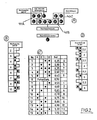
- FIG. 2 The arrangement of such markings and their respective combination into a coding field for controlling a defined working parameter is shown in FIG. 2:
- FIG. 2A shows three coding fields 40A, 40B, 40C, which consist of several markings. These markings can each be in the "zero” state or in the "one” state, the combination of these markings thus making it possible to assign a binary number to a number of values given by the number of the marking for the respective working parameter.
- the coding field 40A is assigned to the working parameter "wax spraying time S", the meaning and the assignment between the assignment of the markings and the wax spraying time in seconds is shown in table B: Are all three markings in the "zero" state (ie, the assigned recesses 30A, 30B and 30G with pads 32A, 32B and 32G), this value is assigned a wax spraying time S of two seconds. If the recesses in the rubber mold are left completely open, this corresponds to a wax spraying time S of ten seconds (Table B below).
- the coding field 40B is assigned to the working parameter "wax injection pressure" and the coding table C shows the values of the wax injection pressure in bar from 0.25 to 1.1 bar resulting from the different assignment of these four markings. It should be emphasized here that the combination No. 6 "0000" includes an average wax injection pressure control of 0.5 bar, which, however, can be controlled externally, this combination of the markings in the coding field 40B thus the manual control via an external potentiometer guaranteed, i.e. practically represents a switch from automatic mode to manual mode, which is integrated in this program.
- FIG. 3 schematically shows the implementation of this coding principle in a wax spraying system according to FIG. 1:
- Circular recesses 30A to 30M are made on the upper side of the upper half of the rubber mold 30, for example these recesses are vulcanized in with the aid of a plate with inserted pins.
- cutouts 30A to 30M thus represent the markings according to FIG. 2.
- Each cutout can be set to one of two binary states, namely it either remains open or it is closed with a suitable insert, for example a plug 32A ... 32M.
- the twelve recesses 30A ... M arranged along the lines AA and BB (or A'-A 'and B'-B') in FIG. 3 are assigned to the three coding fields 40A ... 40C, as explained in FIG is.
- such a rubber mold 30 is shown in the top view approximately in the lower part of FIG. 3, that is to say with a number of open cutouts and with a number of cutouts closed with inserts.
- scanning elements 42A ... 42M are formed on the underside of the pressure plate 14 in the form of plungers, the spatial arrangement of which is such that each (open or closed) recess 30A ... 30M on the top of the rubber mold 30 a corresponding plunger 42A ... 42M on the underside of the
- Pressure plate 14 is assigned, i.e., in practice, the lines A-A and A'-A 'or B-B and B'-B' are each above the other in a common vertical plane.
- the plungers 42A ... 42M projecting downward from the cover plate 14 now also receive this information corresponding to the "binary state" of the upper side of the rubber mold 30, namely by either plunging the plunger 42 into the open recess or as a result of an insert there is pressed upwards when the pressure plate 14 lowers on the rubber mold 30.
- two switching states of the scanning elements are defined, corresponding to the two possible states of each marking in the rubber mold 30.
- the working parameters binary-coded according to coding tables FIG. 2B ... FIG. 2D are accordingly converted into switching states of these scanning elements, which pass the respective binary information on to a circuit 17.
- this binary information about corresponding integrated circuits is used to control the relevant control elements, which is symbolically represented by the output lines U, V, W.
- electronically controlled pressure control valves which can be controlled digitally and control the air pressure in the wax kettle (wax injection pressure) or in the two pneumatic cylinders 28 (FIG. 1) of the wax spraying system.
- the optimal setting of the working parameters must be determined manually on the basis of the model to be sprayed and the rubber mold provided for it. This can be done simply by the worker inserting or replacing the insert elements for the recesses in the rubber mold until the spraying result is optimized. This combination, which is found to be optimal, then remains and controls the working parameters with each subsequent spray cycle, thus ensuring a permanently optimal spray result.
- the "coded” rubber mold is then introduced into the wax spraying system and, as described above, the coding is “adopted” when the pressure plate 14 is lowered, and the current values of the working parameters are obtained from the binary information obtained in this way, and the corresponding pressure control valves are activated.
Landscapes
- Engineering & Computer Science (AREA)
- Mechanical Engineering (AREA)
- Manufacturing & Machinery (AREA)
- Moulds For Moulding Plastics Or The Like (AREA)
- Injection Moulding Of Plastics Or The Like (AREA)
- Coating By Spraying Or Casting (AREA)
- Molds, Cores, And Manufacturing Methods Thereof (AREA)
Abstract
Description
- Die Erfindung betrifft eine Wachsspritzanlage, in der das Wachs von einem Vakuumwachsinjektor in eine Gummiform eingespritzt wird, deren Hälften während des Einspritzvorgangs zwischen zwei Platten zusammengehalten werden, wobei die Arbeitsparameter wie Wachsspritzdruck, Wachsspritzdauer und Anpreßdruck dieser Platten für jede Gummiform individuell eingestellt werden.
- Eine solche Wachsspritzanlage, deren Aufbau und Betriebsweise ist aus der DE-PS 30 24 197 bekannt, so daß hierauf nicht besonders eingegangen zu werden braucht.
- Da in der Praxis für jede unterschiedliche zu gießende Form auch unterschiedliche Werte für die genannten Arbeitsparameter beim Betrieb einer solchen Wachsspritzanlage zu berücksichtigen sind, können bisher nicht mehere Personen an einer solchen Wachsspritzanlage arbeiten, da es für sie praktisch nicht möglich ist, diese Arbeitsparameter und gegebenenfalls die Vakuum-Abschaltung bei nur einer vorhandenen Wachsspritzanlage gleichzeitig manuell einzuregeln, um die Vielzahl an Gummiformen zu handhaben. Die jeweilige individuelle Einstellung der Arbeitsparameter durch die Arbeitskraft, die etwa vier bis zehn Gummiformen gleichzeitig bearbeiten kann (insbesondere wegen der benötigten Auskühlungszeit des Wachses) ist zeitaufwendig und bedeutet letztlich keine optimale Ausnutzung der vorhandenen Wachsspritzanlage.
- Aufgabe der Erfindung ist es daher, eine solche Wachsspritzanlage bzw. deren Steuerung so weiterzubilden, daß diese Einstellzeiten für die einzelnen Arbeitsparameter entfallen und somit der Auslastungsgrad einer Wachsspritzanlage wesentlich erhöht wird.
- Erfindungsgemäß wird diese Aufgabe gemäß dem kennzeichnenden Teil der Patentanspruchs 1 gelöst,
- Der Grundgedanke der Erfindung betsteht also in der vollautomatischen Einstellung der Arbeitsparameter der Wachsspritzanlage durch die Gummiform selbst, ohne daß es hierzu noch manueller Einstellvorgänge seitens der Bedienkraft bedarf. Dies ermöglicht den Einsatz von bis zu vier Arbeitskräften an nur einem Vakuum-Wachsinjektor, die beispielsweise halbkreisförmig zum Gerät sitzend angeordnet sind. Die vollautomatische "Eingabe" der Arbeitsparameter hat auch eine Steigerung der Präzision der Spritzergebnisse zur Folge, da einmal als optimal ermittelte Parameterkombinationen immer wieder genau reproduziert werden. Dies ist insbesondere bei der Herstellung von Goldteilen von besonderer Bedeutung, wo es bei manuellen Einstellungen der Arbeitsparameter nicht auszuschließen ist, daß beim späteren Gießen das genaue Gewicht nicht erreicht wird; dies ist bei einer Gewichtsüberschreitung nachteilig für den Hänler, da er mehr Gold als kalkuliert abgibt, bei einer Gewichtsunterschreitung nachteilig für den Käufter, da er weniger Gold erhält als angegeben, was zu berechtigten Reklamationen führen kann.
- Die erfindungsgemäße Wachsspritzanlage beseitigt durch die präzise Reproduzierbarkeit der Arbeitsparameter und damit der Reproduzierbarkeit des Wachsmodells diese Schwierigkeiten bei der Herstellung von Gußteilen auf der Grundlage des Wachsausschmelzverfahrens. Sie realisiert dieses im wesentlichen durch eine korrespondierende räumliche Anordnung von Kodierfeldern sowohl auf der Oberseite der Gummiform, als auch auf der Unterseite der Anpreßplatte. Jede Kodierung besteht aus einer Kombination von Markierungen, die ihrerseits aus einer definierten Aussparung bestehen,die in der Gummiform eingebracht sind. Je nach Wert des Arbeitsparameters, sind solche Aussparungen in der Gummiform einfach mit Stöpseln oder Deckeln wieder abzudecken, so daß die in der Pressenplatte angeordneten Abtastelemente die erforderliche binäre Information Null bzw. Eins auf einfachste Weise durch Freilassen der Aussparung in der Gummiform oder durch Verschluß dieser Aussparung mittels eines Einsatzelements übermittelt bekommen.
- Weitere Ausgestaltungen sind den Unteransprüchen entnehmbar.
- Ein Ausführungsbeispiel der erfindungsgemäßen Wachsspritzanlage, wird im folgenden anhand von Zeichnungen näher erläutert, es zeigen:
- Figur 1: Einen Vertikalschnitt durch eine Wachsspritzanlage,
- Figur 2: das erfindungsgemäße Prinzip der Kodierung, und
- Figur 3: eine schematische Darstellung der Umsetzung der Kodierung gemäß Figur 2 auf einer Wachsspritzanlage gemäß Figur 1.
- Figur 1 zeigt im Vertikalschnitt eine Wachsspritzanlage; die Einzelheiten und der Betrieb dieser Wachsspritzanlage sind aus der DE-PS 30 24 197 entnehmbar und werden hier nicht näher erläutert. Als hier erfindungswesentlich soll lediglich folgendes festgehalten werden: Die zweigeteilte Gummiform (Matrize, Spritzgießform) 30 liegt auf einer Auflageplatte 15 mit ihrer Öffnung gegenüber der Einspritzdüse 31. Zum Zusammenpresssen der beiden Hälften der Gummiform 30 dient eine Anpreßplatte 14, die mittels vier Verbindungsbolzen 19 (zwei sichtbar in Figur 1) gehalten ist, die sich bis unterhalb der Anlageplatte 15 erstrecken und dort paarweise über eine Lasche 18 verbunden sind. Beide Laschen 18 werden vom Kolben je einer Kolben-Zylindereinheit 28 beaufschlagt, bei deren Betätigung die Anpreßplatte 14 auf die Oberseite der Gummiform 30 aufgepreßt wird und diese festklemmt.
- Zur Steuerung der hierbei wesentlichen Arbeitsparameter wie Wachsspritzdruck, Wachsspritzdauer und Anpreßdruck der Platten ist auf der Gummiform 30 eine Kodierung in Form von Aussparungen vorgesehen, die wahlweise freibleiben können oder mit einem geeigneten Einsatz abschließbar sind.
- Die Anordnung solcher Markierungen und ihre jeweilige Zusammenfassung zu einem Kodierfeld zur Steuerung eines definierten Arbeitsparameters ist in Figur 2 dargetellt:
- Figur 2A zeigt drei Kodierfelder 40A, 40B, 40C, die aus mehreren Markierungen bestehen. Diese Markierungen können sich jeweils im Zustand "Null" oder im Zustand "Eins" befinden, die Kombination dieser Markierungen ermöglicht somit die Zuordnung einer Binärzahl zu einer durch die Anzahl der Markierung gegebenen Werteanzahl für den jeweiligen Arbeitsparameter.
- Das Kodierfeld 40A ist dem Arbeitsparameter "Wachsspritzzeit S" zugeordnet, die Bedeutung und die Zuordnung zwischen der Belegung der Markierungen und der Wachsspritzzeit in Sekunden ist in Tabelle B dargestellt: Befinden sich sämtliche drei Markierungen im Zustand "Null" (d.h., sind die zugeordneten Aussparungen 30A, 30B und 30G mit Einlagen 32A,32B und 32G aufgefüllt), so ist diesem Wert eine Wachsspritzzeit S von zwei Sekunden zugeordnet. Bei vollständigem Offenlassen der Aussparungen in der Gummiform entspricht dies einer Wachsspritzzeit S von zehn Sekunden (Tabelle B unten).
- Das Kodierfeld 40B ist dem Arbeitsparameter "Wachsspritzdruck" zugeordnet und die Kodiertabelle C zeigt die sich aus der unterschiedlichen Belegung dieser vier Markierungen ergebenden Werte des Wachsspritzdruckes in bar von 0,25 bis 1,1 bar. Hierbei ist hervorzuheben, daß die Kombination Nr. 6 "0000" eine mittlere Wachsspritzdruckregelung von 0,5 bar beinhaltet, die jedoch extern steuerbar ist, diese Kombination der Markierungen im Kodierfeld 40B somit die manuelle Steuerung über ein Außenpotentiometer gewährleistet, also praktisch eine Umschaltung von Automatikbetrieb auf Handbetrieb darstellt, die in diesem Programm integriert ist.
- Die vier Markierungen des Kodierfeldes 40B ermöglichen demnach bis zu 2⁴ = 16 Kombinationen des Wachsspritzdruckes.
- Schließlich dient das Kodierfeld 40C zur Steuerung des Anpreßdruckes gemäß Kodiertabelle D in Figur 2, hieraus ist zu entnehmen, daß infolge der drei Markierungen des Kodierfeldes 40C insgesamt 2³ = 8 verschiedene Kombinationen von 2,5 bis 6 bar eingestellt werden können.
- Eine einzelne Markierung "automatische Vakuumabschaltung" regelt die Zuschaltung des Vakuums (Aussparung in der Gummiform offen = ohne Vakuum, Aussparung in der Gummiform mit Einsatz geschlossen = mit Vakuum), eine weitere einzelne Markierung "Anpreßdruck hinten" dient zur Ansteuerung eines zusätzlichen Zylinders bei Überlänge der Gummiform oder der Anpreßplatte. Figur 3 zeigt schematisch die Umsetzung diese Kodierprinzips bei einer Wachsspritzanlage gemäß Figur 1:
- Auf der Oberseite der oberen Hälfte der Gummiform 30 sind kreisförmige Aussparungen 30A bis 30M eingebracht, beispielsweise werden mit Hilfe einer Platte mit eingesetzten Stiften diese Aussparungen mit einvulkanisiert.
- Diese Aussparungen 30A bis 30M stellen also die Markierungen gemäß Figur 2 dar. Jede Aussparung kann in einen von zwei binären Zuständen versetzt werden, sie bleibt nämlich entweder offen, oder sie wird mit einem geeigneten Einsatz, beispielsweise einem Stöpsel 32A...32M verschlossen.
- Die in Figur 3 entlang den Linien A-A und B-B (bzw. A′-A′ und B′-B′) angeordneten zwölf Aussparungen 30A...M sind den drei Kodierfeldern 40A...40C zugeteilt, wie dies in Figur 2 erläutert ist.
- Durch Zusetzen der Aussparungen mit Stöpseln läßt sich dabei jede der in Figur 2B,2C,2D dargestellten Wertekombinationen erreichen.
- In der Praxis stellt sich also eine solche Gummiform 30 in der Aufsicht etwa im unteren Teil der Figur 3 dar, also mit einer Anzahl von offenen Aussparungen und mit einer Anzahl von mit Einsätzen abgeschlossenen Aussparungen.
- Entsprechend dieser Anordnung der Kodierfelder bzw. Markierungen auf der Gummiform 30 sin auf der Unterseite der Anpreßplatte 14 Abtastelemente 42A...42M in Form von Stößeln ausgebildet, deren räumliche Anordnung so ist, daß jeder (offenen oder geschlossenen) Aussparung 30A...30M auf der Oberseite der Gummiform 30 ein entsprechender Stößel 42A...42M auf der Unterseite der
- Anpreßplatte 14 zugeordnet ist, d.h., bei der praktischen Anwendung liegen die Linien A-A und A′-A′ bzw. B-B und B′-B′ jeweils in einer gemeinsamen vertikalen Ebene übereinander.
- Die nach unten aus der Abdeckplatte 14 herausragenden Stößel 42A...42M nehmen nun ebenfalls korrespondierend zum "binären Zustand" der Oberseite der Gummiform 30 diese Information auf, in dem nämlich entweder der Stößel 42 in die offene Aussparung eintaucht oder infolge eines dort vorhandenen Einsatzes nach oben gedrückt wird, wenn sich die Anpreßplatte 14 auf die Gummiform 30 absenkt. Dadurch werden also zwei Schaltzustände der Abtastelemente definiert, entsprechend den beiden möglichen Zuständen jeder Markierung in der Gummiform 30.
- Die gemäß Kodiertabellen Figur 2B... Figur 2D binär kodierten Arbeitsparameter werden demnach in Schaltzustände dieser Abtastelemente umgesetzt, die die jeweilige binäre Information an einen Schaltkreis 17 weitergeben. In diesem Schaltkreis werden diese binären Informationen über entsprechende integrierte Schaltungen zur Ansteuerung der betreffenden Regelelemente verwendet, was symbolisch durch die Ausgangsleitungen U,V,W dargestellt ist. Hierbei werden zweckmäßigerweise elektronisch gesteuerte Druckregelventile eingesetzt, die digital angesteuert werden können und den Luftdruck im Wachskessel (Wachsspritzdruck) bzw. in den zwei Pneumatikzylindern 28 (Figur 1) der Wachsspritzanlage steuern.
- Im folgenden soll noch kurz ein gesamter Arbeitszyklus der Wachsspritzanlage erläutert werden:
- Zunächst muß anhand des zu spritzenden Modells und der dafür vorgeshenen Gummiform die optimale Einstellung der Arbeitsparameter manuell ermittelt werden. Dies kann einfach dadurch erfolgen, daß die Arbeitskraft die Einsatzelemente für die Aussparungen in der Gummiform einsetzt bzw. so lange austauscht, bis das Spritzergebnis optimiert ist. Diese als optimal festgestellte Kombination bleibt dann bestehen und steuert bei jedem nachfolgenden Spritztakt die Arbeitsparameter und gewährleistet somit ein dauerhalft optimales Spritzergebnis.
- Die so "kodierte" Gummiform wird dann jeweils in die Wachsspritzanlage eingeführt und die Kodierung wird, wie oben beschrieben, beim Absenken der Anpreßplatte 14 "übernommen" und aus der derart gewonnenen Binärinformation werden die aktuellen Werte der Arbeitsparameter gewonnen und die entsprechenden Druckregelventile angesteuert.
Claims (5)
dadurch gekennzeichnet, daß jede Gummiform (30) für die ihr zugeordneten Arbeitsparameter eine Kodierung aus einer Kombination von Markierungen aufweist, und daß dieser Kodierung Abtastelemente (42) zugeordnet sind, die nach dem Einführen der Gummiform (30) in die Wachsspritzposition den kodierten Wert des/der Arbeitsparameter (s) erfassen und das jeweils zugeordnete Regelelement zur Einstellung dieses Wertes ansteuern.
Applications Claiming Priority (2)
| Application Number | Priority Date | Filing Date | Title |
|---|---|---|---|
| DE3837713A DE3837713A1 (de) | 1988-11-07 | 1988-11-07 | Verfahren und vorrichtung zur steuerung einer wachsspritzanlage |
| DE3837713 | 1988-11-07 |
Publications (3)
| Publication Number | Publication Date |
|---|---|
| EP0368012A2 true EP0368012A2 (de) | 1990-05-16 |
| EP0368012A3 EP0368012A3 (de) | 1991-07-03 |
| EP0368012B1 EP0368012B1 (de) | 1994-08-03 |
Family
ID=6366641
Family Applications (1)
| Application Number | Title | Priority Date | Filing Date |
|---|---|---|---|
| EP89118866A Expired - Lifetime EP0368012B1 (de) | 1988-11-07 | 1989-10-11 | Verfahren und Vorrichtung zur Steuerung einer Wachspritzanlage |
Country Status (4)
| Country | Link |
|---|---|
| EP (1) | EP0368012B1 (de) |
| AT (1) | ATE109392T1 (de) |
| DE (2) | DE3837713A1 (de) |
| ES (1) | ES2057049T3 (de) |
Cited By (3)
| Publication number | Priority date | Publication date | Assignee | Title |
|---|---|---|---|---|
| WO1994029049A1 (en) * | 1993-06-09 | 1994-12-22 | Nicem S.P.A. | Automation of a moulding machine by means of programmable logic controllers |
| EP0790112A1 (de) * | 1996-02-02 | 1997-08-20 | Georg Taubmann | Verfahren und Anordnung zum Verwalten der Formen für die maschinelle Herstellung von Formkörpern aus Beton oder artverwandten Materialien |
| EP1977648A3 (de) * | 2004-05-11 | 2009-04-01 | Stork Titan B.V. | Formung |
Families Citing this family (3)
| Publication number | Priority date | Publication date | Assignee | Title |
|---|---|---|---|---|
| DE4112364A1 (de) * | 1991-04-16 | 1992-10-22 | Dogendorf Gmbh & Co Kg | Spritzgiessverfahren und vorrichtung zu seiner durchfuehrung |
| US5795511A (en) * | 1995-06-06 | 1998-08-18 | Fast Heat, Inc. | Method and apparatus for controlling injection-molding systems |
| DE102004050290A1 (de) * | 2004-10-15 | 2006-04-20 | Krauss-Maffei Kunststofftechnik Gmbh | Verfahren und Vorrichtung zum Herstellen von unterschiedlich beschichteten Kunststoffformteilen |
Family Cites Families (3)
| Publication number | Priority date | Publication date | Assignee | Title |
|---|---|---|---|---|
| DE3024197C2 (de) * | 1980-06-27 | 1982-07-08 | Alexander Dipl.-Ing. 7530 Pforzheim Messing | Vorichtung zum Halten und Führen einer mehrteiligen Spritzgießform, insbesondere bei einer Wachseinspritzmaschine |
| GB2124967B (en) * | 1982-08-04 | 1986-01-02 | Hamilton Machinery Sales Limit | Mould identification |
| DE3505155A1 (de) * | 1985-02-15 | 1986-08-21 | Elastogran Maschinenbau GmbH, 2844 Lemförde | Vorrichtung zur herstellung von formteilen aus mehrkomponentenkunststoff, insbesondere polyurethan, mit einer programmsteuerung |
-
1988
- 1988-11-07 DE DE3837713A patent/DE3837713A1/de active Granted
-
1989
- 1989-10-11 ES ES89118866T patent/ES2057049T3/es not_active Expired - Lifetime
- 1989-10-11 EP EP89118866A patent/EP0368012B1/de not_active Expired - Lifetime
- 1989-10-11 AT AT89118866T patent/ATE109392T1/de not_active IP Right Cessation
- 1989-10-11 DE DE58908141T patent/DE58908141D1/de not_active Expired - Fee Related
Cited By (11)
| Publication number | Priority date | Publication date | Assignee | Title |
|---|---|---|---|---|
| WO1994029049A1 (en) * | 1993-06-09 | 1994-12-22 | Nicem S.P.A. | Automation of a moulding machine by means of programmable logic controllers |
| US5406059A (en) * | 1993-06-09 | 1995-04-11 | Nicem S.P.A. | Molding machine, particularly of the centrifugal type, for low melting materials, synthetic materials or the like |
| EP0790112A1 (de) * | 1996-02-02 | 1997-08-20 | Georg Taubmann | Verfahren und Anordnung zum Verwalten der Formen für die maschinelle Herstellung von Formkörpern aus Beton oder artverwandten Materialien |
| US5997271A (en) * | 1996-02-02 | 1999-12-07 | Taubmann; Georg | Device for managing molds used for mechanically producing molded objects of building material |
| EP1977648A3 (de) * | 2004-05-11 | 2009-04-01 | Stork Titan B.V. | Formung |
| US7819650B2 (en) | 2004-05-11 | 2010-10-26 | Stork Titan B.V. | Moulding |
| US8747934B2 (en) | 2004-05-11 | 2014-06-10 | Stork Titan B.V. | Moulding |
| US9060544B2 (en) | 2004-05-11 | 2015-06-23 | Stork Titan B.V. | Moulding |
| US9986755B2 (en) | 2004-05-11 | 2018-06-05 | Stork Titan B.V. | Moulding |
| US11013255B2 (en) | 2004-05-11 | 2021-05-25 | Stork Titan B.V. | Moulding |
| US11793227B2 (en) | 2004-05-11 | 2023-10-24 | Stork Titan B.V. | Moulding |
Also Published As
| Publication number | Publication date |
|---|---|
| DE3837713A1 (de) | 1990-05-10 |
| DE58908141D1 (de) | 1994-09-08 |
| EP0368012B1 (de) | 1994-08-03 |
| ES2057049T3 (es) | 1994-10-16 |
| EP0368012A3 (de) | 1991-07-03 |
| DE3837713C2 (de) | 1990-10-11 |
| ATE109392T1 (de) | 1994-08-15 |
Similar Documents
| Publication | Publication Date | Title |
|---|---|---|
| DE4117454C2 (de) | Anschlußapplikator zum Anbringen elektrischer Anschlüsse | |
| EP0343661A2 (de) | Verfahren und Vorrichtung zum Herstellen von verschweissten Stanzteilen | |
| DE102019135427A1 (de) | Vorrichtung zur Herstellung von Betonsteinen | |
| DE3016140A1 (de) | Verfahren zum herstellen von aus stahlband geformten loch- und schneidbzw. stanzwerkzeugen | |
| EP0368012B1 (de) | Verfahren und Vorrichtung zur Steuerung einer Wachspritzanlage | |
| DE3936247A1 (de) | Verfahren und giesskaesten zur herstellung von dentalplatten aus harz | |
| EP0683031A2 (de) | Verfahren zum Herstellen mehrteiliger Spritzguss-Formteile und Werkzeug zur Durchführung des Verfahrens | |
| DE3423543A1 (de) | Presse und verfahren zur herstellung derselben | |
| DE2535817B2 (de) | Klemmeinrichtung an einer Revolverstanze | |
| DE3127797A1 (de) | Aufspann- und anschlussvorrichtung fuer werkzeuge von spritzgiessmaschinen und damit zu verwendendes werkzeug | |
| DE19733310A1 (de) | Gerät und Verfahren zur Herstellung von Zahnprothesen mit einer Kunstharzbasis | |
| DE3928971C2 (de) | ||
| WO2017025266A1 (de) | Sandgussformkennzeichnungsvorrichtung | |
| DE3738164A1 (de) | Vorrichtung zur bearbeitung und bereitstellung von tapepaks fuer bestueckautomaten | |
| DE4325981C1 (de) | Vorrichtung für die Herstellung von Öffnungen in einer Gießform | |
| DE2925902A1 (de) | Signalvorrichtung zur erzeugung von elektrischen steuersignalen fuer eine steuervorrichtung einer presse | |
| DE2228037A1 (de) | Verfahren und vorrichtung zur steuerung der manipulatorbewegungen bei einer umformmaschine, insbesondere bei einer freiform-schmiedepresse | |
| DE3911076A1 (de) | Vorrichtung zur herstellung von gratfreien werkstuecken aus duroplast | |
| DE202019106162U1 (de) | Intelligentes automatisches Formenwechselsystem | |
| DE2918081A1 (de) | Anlage zur herstellung von giesskernen | |
| DE3024311A1 (de) | Beschickungseinrichtung fuer kokillengussmaschine | |
| DE762813C (de) | Vorrichtung zum Herstellen von Formkoerpern aus plastischen Massen | |
| DE4241955C2 (de) | Werkzeugaufnahme | |
| DE10037352A1 (de) | Muffelbasis | |
| DE1704359C (de) | Preßwerkzeug zum Herstellen von Dichtungsringen |
Legal Events
| Date | Code | Title | Description |
|---|---|---|---|
| PUAI | Public reference made under article 153(3) epc to a published international application that has entered the european phase |
Free format text: ORIGINAL CODE: 0009012 |
|
| AK | Designated contracting states |
Kind code of ref document: A2 Designated state(s): AT BE CH DE ES FR GB GR IT LI LU NL |
|
| PUAL | Search report despatched |
Free format text: ORIGINAL CODE: 0009013 |
|
| AK | Designated contracting states |
Kind code of ref document: A3 Designated state(s): AT BE CH DE ES FR GB GR IT LI LU NL |
|
| 17P | Request for examination filed |
Effective date: 19910903 |
|
| 17Q | First examination report despatched |
Effective date: 19930304 |
|
| GRAA | (expected) grant |
Free format text: ORIGINAL CODE: 0009210 |
|
| AK | Designated contracting states |
Kind code of ref document: B1 Designated state(s): AT BE CH DE ES FR GB GR IT LI LU NL |
|
| PG25 | Lapsed in a contracting state [announced via postgrant information from national office to epo] |
Ref country code: NL Effective date: 19940803 Ref country code: GR Free format text: LAPSE BECAUSE OF FAILURE TO SUBMIT A TRANSLATION OF THE DESCRIPTION OR TO PAY THE FEE WITHIN THE PRESCRIBED TIME-LIMIT Effective date: 19940803 Ref country code: BE Effective date: 19940803 |
|
| REF | Corresponds to: |
Ref document number: 109392 Country of ref document: AT Date of ref document: 19940815 Kind code of ref document: T |
|
| REF | Corresponds to: |
Ref document number: 58908141 Country of ref document: DE Date of ref document: 19940908 |
|
| REG | Reference to a national code |
Ref country code: ES Ref legal event code: FG2A Ref document number: 2057049 Country of ref document: ES Kind code of ref document: T3 |
|
| ITF | It: translation for a ep patent filed | ||
| PG25 | Lapsed in a contracting state [announced via postgrant information from national office to epo] |
Ref country code: LU Free format text: LAPSE BECAUSE OF NON-PAYMENT OF DUE FEES Effective date: 19941031 |
|
| ET | Fr: translation filed | ||
| GBT | Gb: translation of ep patent filed (gb section 77(6)(a)/1977) |
Effective date: 19941110 |
|
| NLV1 | Nl: lapsed or annulled due to failure to fulfill the requirements of art. 29p and 29m of the patents act | ||
| PLBE | No opposition filed within time limit |
Free format text: ORIGINAL CODE: 0009261 |
|
| STAA | Information on the status of an ep patent application or granted ep patent |
Free format text: STATUS: NO OPPOSITION FILED WITHIN TIME LIMIT |
|
| 26N | No opposition filed | ||
| PGFP | Annual fee paid to national office [announced via postgrant information from national office to epo] |
Ref country code: GB Payment date: 20010917 Year of fee payment: 13 |
|
| PGFP | Annual fee paid to national office [announced via postgrant information from national office to epo] |
Ref country code: FR Payment date: 20011017 Year of fee payment: 13 |
|
| PGFP | Annual fee paid to national office [announced via postgrant information from national office to epo] |
Ref country code: CH Payment date: 20011023 Year of fee payment: 13 Ref country code: AT Payment date: 20011023 Year of fee payment: 13 |
|
| REG | Reference to a national code |
Ref country code: GB Ref legal event code: IF02 |
|
| PG25 | Lapsed in a contracting state [announced via postgrant information from national office to epo] |
Ref country code: GB Free format text: LAPSE BECAUSE OF NON-PAYMENT OF DUE FEES Effective date: 20021011 Ref country code: AT Free format text: LAPSE BECAUSE OF NON-PAYMENT OF DUE FEES Effective date: 20021011 |
|
| PG25 | Lapsed in a contracting state [announced via postgrant information from national office to epo] |
Ref country code: LI Free format text: LAPSE BECAUSE OF NON-PAYMENT OF DUE FEES Effective date: 20021031 Ref country code: CH Free format text: LAPSE BECAUSE OF NON-PAYMENT OF DUE FEES Effective date: 20021031 |
|
| GBPC | Gb: european patent ceased through non-payment of renewal fee |
Effective date: 20021011 |
|
| REG | Reference to a national code |
Ref country code: CH Ref legal event code: PL |
|
| PG25 | Lapsed in a contracting state [announced via postgrant information from national office to epo] |
Ref country code: FR Free format text: LAPSE BECAUSE OF NON-PAYMENT OF DUE FEES Effective date: 20030630 |
|
| PGFP | Annual fee paid to national office [announced via postgrant information from national office to epo] |
Ref country code: DE Payment date: 20030812 Year of fee payment: 15 |
|
| REG | Reference to a national code |
Ref country code: FR Ref legal event code: ST |
|
| PGFP | Annual fee paid to national office [announced via postgrant information from national office to epo] |
Ref country code: ES Payment date: 20031029 Year of fee payment: 15 |
|
| PG25 | Lapsed in a contracting state [announced via postgrant information from national office to epo] |
Ref country code: ES Free format text: LAPSE BECAUSE OF NON-PAYMENT OF DUE FEES Effective date: 20041013 |
|
| PG25 | Lapsed in a contracting state [announced via postgrant information from national office to epo] |
Ref country code: DE Free format text: LAPSE BECAUSE OF NON-PAYMENT OF DUE FEES Effective date: 20050503 |
|
| PG25 | Lapsed in a contracting state [announced via postgrant information from national office to epo] |
Ref country code: IT Free format text: LAPSE BECAUSE OF NON-PAYMENT OF DUE FEES Effective date: 20051011 |
|
| REG | Reference to a national code |
Ref country code: ES Ref legal event code: FD2A Effective date: 20041013 |