EP0368016A2 - Machine de fabrication de sachets tubulaires - Google Patents
Machine de fabrication de sachets tubulaires Download PDFInfo
- Publication number
- EP0368016A2 EP0368016A2 EP89118904A EP89118904A EP0368016A2 EP 0368016 A2 EP0368016 A2 EP 0368016A2 EP 89118904 A EP89118904 A EP 89118904A EP 89118904 A EP89118904 A EP 89118904A EP 0368016 A2 EP0368016 A2 EP 0368016A2
- Authority
- EP
- European Patent Office
- Prior art keywords
- cross
- tubular bag
- jaws
- welding
- bag machine
- Prior art date
- Legal status (The legal status is an assumption and is not a legal conclusion. Google has not performed a legal analysis and makes no representation as to the accuracy of the status listed.)
- Granted
Links
Images

Classifications
-
- B—PERFORMING OPERATIONS; TRANSPORTING
- B29—WORKING OF PLASTICS; WORKING OF SUBSTANCES IN A PLASTIC STATE IN GENERAL
- B29C—SHAPING OR JOINING OF PLASTICS; SHAPING OF MATERIAL IN A PLASTIC STATE, NOT OTHERWISE PROVIDED FOR; AFTER-TREATMENT OF THE SHAPED PRODUCTS, e.g. REPAIRING
- B29C66/00—General aspects of processes or apparatus for joining preformed parts
- B29C66/80—General aspects of machine operations or constructions and parts thereof
- B29C66/82—Pressure application arrangements, e.g. transmission or actuating mechanisms for joining tools or clamps
- B29C66/822—Transmission mechanisms
- B29C66/8221—Scissor or lever mechanisms, i.e. involving a pivot point
-
- B—PERFORMING OPERATIONS; TRANSPORTING
- B29—WORKING OF PLASTICS; WORKING OF SUBSTANCES IN A PLASTIC STATE IN GENERAL
- B29C—SHAPING OR JOINING OF PLASTICS; SHAPING OF MATERIAL IN A PLASTIC STATE, NOT OTHERWISE PROVIDED FOR; AFTER-TREATMENT OF THE SHAPED PRODUCTS, e.g. REPAIRING
- B29C65/00—Joining or sealing of preformed parts, e.g. welding of plastics materials; Apparatus therefor
- B29C65/02—Joining or sealing of preformed parts, e.g. welding of plastics materials; Apparatus therefor by heating, with or without pressure
- B29C65/18—Joining or sealing of preformed parts, e.g. welding of plastics materials; Apparatus therefor by heating, with or without pressure using heated tools
-
- B—PERFORMING OPERATIONS; TRANSPORTING
- B29—WORKING OF PLASTICS; WORKING OF SUBSTANCES IN A PLASTIC STATE IN GENERAL
- B29C—SHAPING OR JOINING OF PLASTICS; SHAPING OF MATERIAL IN A PLASTIC STATE, NOT OTHERWISE PROVIDED FOR; AFTER-TREATMENT OF THE SHAPED PRODUCTS, e.g. REPAIRING
- B29C66/00—General aspects of processes or apparatus for joining preformed parts
- B29C66/01—General aspects dealing with the joint area or with the area to be joined
- B29C66/02—Preparation of the material, in the area to be joined, prior to joining or welding
- B29C66/024—Thermal pre-treatments
- B29C66/0242—Heating, or preheating, e.g. drying
-
- B—PERFORMING OPERATIONS; TRANSPORTING
- B29—WORKING OF PLASTICS; WORKING OF SUBSTANCES IN A PLASTIC STATE IN GENERAL
- B29C—SHAPING OR JOINING OF PLASTICS; SHAPING OF MATERIAL IN A PLASTIC STATE, NOT OTHERWISE PROVIDED FOR; AFTER-TREATMENT OF THE SHAPED PRODUCTS, e.g. REPAIRING
- B29C66/00—General aspects of processes or apparatus for joining preformed parts
- B29C66/01—General aspects dealing with the joint area or with the area to be joined
- B29C66/05—Particular design of joint configurations
- B29C66/10—Particular design of joint configurations particular design of the joint cross-sections
- B29C66/11—Joint cross-sections comprising a single joint-segment, i.e. one of the parts to be joined comprising a single joint-segment in the joint cross-section
- B29C66/112—Single lapped joints
- B29C66/1122—Single lap to lap joints, i.e. overlap joints
-
- B—PERFORMING OPERATIONS; TRANSPORTING
- B29—WORKING OF PLASTICS; WORKING OF SUBSTANCES IN A PLASTIC STATE IN GENERAL
- B29C—SHAPING OR JOINING OF PLASTICS; SHAPING OF MATERIAL IN A PLASTIC STATE, NOT OTHERWISE PROVIDED FOR; AFTER-TREATMENT OF THE SHAPED PRODUCTS, e.g. REPAIRING
- B29C66/00—General aspects of processes or apparatus for joining preformed parts
- B29C66/40—General aspects of joining substantially flat articles, e.g. plates, sheets or web-like materials; Making flat seams in tubular or hollow articles; Joining single elements to substantially flat surfaces
- B29C66/41—Joining substantially flat articles ; Making flat seams in tubular or hollow articles
- B29C66/43—Joining a relatively small portion of the surface of said articles
- B29C66/431—Joining the articles to themselves
- B29C66/4312—Joining the articles to themselves for making flat seams in tubular or hollow articles, e.g. transversal seams
-
- B—PERFORMING OPERATIONS; TRANSPORTING
- B29—WORKING OF PLASTICS; WORKING OF SUBSTANCES IN A PLASTIC STATE IN GENERAL
- B29C—SHAPING OR JOINING OF PLASTICS; SHAPING OF MATERIAL IN A PLASTIC STATE, NOT OTHERWISE PROVIDED FOR; AFTER-TREATMENT OF THE SHAPED PRODUCTS, e.g. REPAIRING
- B29C66/00—General aspects of processes or apparatus for joining preformed parts
- B29C66/80—General aspects of machine operations or constructions and parts thereof
- B29C66/82—Pressure application arrangements, e.g. transmission or actuating mechanisms for joining tools or clamps
- B29C66/822—Transmission mechanisms
- B29C66/8225—Crank mechanisms
-
- B—PERFORMING OPERATIONS; TRANSPORTING
- B29—WORKING OF PLASTICS; WORKING OF SUBSTANCES IN A PLASTIC STATE IN GENERAL
- B29C—SHAPING OR JOINING OF PLASTICS; SHAPING OF MATERIAL IN A PLASTIC STATE, NOT OTHERWISE PROVIDED FOR; AFTER-TREATMENT OF THE SHAPED PRODUCTS, e.g. REPAIRING
- B29C66/00—General aspects of processes or apparatus for joining preformed parts
- B29C66/80—General aspects of machine operations or constructions and parts thereof
- B29C66/82—Pressure application arrangements, e.g. transmission or actuating mechanisms for joining tools or clamps
- B29C66/822—Transmission mechanisms
- B29C66/8226—Cam mechanisms; Wedges; Eccentric mechanisms
- B29C66/82263—Follower pin or roller cooperating with a groove
-
- B—PERFORMING OPERATIONS; TRANSPORTING
- B29—WORKING OF PLASTICS; WORKING OF SUBSTANCES IN A PLASTIC STATE IN GENERAL
- B29C—SHAPING OR JOINING OF PLASTICS; SHAPING OF MATERIAL IN A PLASTIC STATE, NOT OTHERWISE PROVIDED FOR; AFTER-TREATMENT OF THE SHAPED PRODUCTS, e.g. REPAIRING
- B29C66/00—General aspects of processes or apparatus for joining preformed parts
- B29C66/80—General aspects of machine operations or constructions and parts thereof
- B29C66/83—General aspects of machine operations or constructions and parts thereof characterised by the movement of the joining or pressing tools
- B29C66/832—Reciprocating joining or pressing tools
- B29C66/8322—Joining or pressing tools reciprocating along one axis
- B29C66/83221—Joining or pressing tools reciprocating along one axis cooperating reciprocating tools, each tool reciprocating along one axis
-
- B—PERFORMING OPERATIONS; TRANSPORTING
- B29—WORKING OF PLASTICS; WORKING OF SUBSTANCES IN A PLASTIC STATE IN GENERAL
- B29C—SHAPING OR JOINING OF PLASTICS; SHAPING OF MATERIAL IN A PLASTIC STATE, NOT OTHERWISE PROVIDED FOR; AFTER-TREATMENT OF THE SHAPED PRODUCTS, e.g. REPAIRING
- B29C66/00—General aspects of processes or apparatus for joining preformed parts
- B29C66/80—General aspects of machine operations or constructions and parts thereof
- B29C66/84—Specific machine types or machines suitable for specific applications
- B29C66/849—Packaging machines
- B29C66/8491—Packaging machines welding through a filled container, e.g. tube or bag
-
- B—PERFORMING OPERATIONS; TRANSPORTING
- B29—WORKING OF PLASTICS; WORKING OF SUBSTANCES IN A PLASTIC STATE IN GENERAL
- B29C—SHAPING OR JOINING OF PLASTICS; SHAPING OF MATERIAL IN A PLASTIC STATE, NOT OTHERWISE PROVIDED FOR; AFTER-TREATMENT OF THE SHAPED PRODUCTS, e.g. REPAIRING
- B29C66/00—General aspects of processes or apparatus for joining preformed parts
- B29C66/90—Measuring or controlling the joining process
- B29C66/92—Measuring or controlling the joining process by measuring or controlling the pressure, the force, the mechanical power or the displacement of the joining tools
- B29C66/922—Measuring or controlling the joining process by measuring or controlling the pressure, the force, the mechanical power or the displacement of the joining tools by measuring the pressure, the force, the mechanical power or the displacement of the joining tools
- B29C66/9221—Measuring or controlling the joining process by measuring or controlling the pressure, the force, the mechanical power or the displacement of the joining tools by measuring the pressure, the force, the mechanical power or the displacement of the joining tools by measuring the pressure, the force or the mechanical power
- B29C66/92211—Measuring or controlling the joining process by measuring or controlling the pressure, the force, the mechanical power or the displacement of the joining tools by measuring the pressure, the force, the mechanical power or the displacement of the joining tools by measuring the pressure, the force or the mechanical power with special measurement means or methods
-
- B—PERFORMING OPERATIONS; TRANSPORTING
- B29—WORKING OF PLASTICS; WORKING OF SUBSTANCES IN A PLASTIC STATE IN GENERAL
- B29C—SHAPING OR JOINING OF PLASTICS; SHAPING OF MATERIAL IN A PLASTIC STATE, NOT OTHERWISE PROVIDED FOR; AFTER-TREATMENT OF THE SHAPED PRODUCTS, e.g. REPAIRING
- B29C66/00—General aspects of processes or apparatus for joining preformed parts
- B29C66/90—Measuring or controlling the joining process
- B29C66/92—Measuring or controlling the joining process by measuring or controlling the pressure, the force, the mechanical power or the displacement of the joining tools
- B29C66/924—Measuring or controlling the joining process by measuring or controlling the pressure, the force, the mechanical power or the displacement of the joining tools by controlling or regulating the pressure, the force, the mechanical power or the displacement of the joining tools
- B29C66/9241—Measuring or controlling the joining process by measuring or controlling the pressure, the force, the mechanical power or the displacement of the joining tools by controlling or regulating the pressure, the force, the mechanical power or the displacement of the joining tools by controlling or regulating the pressure, the force or the mechanical power
-
- B—PERFORMING OPERATIONS; TRANSPORTING
- B29—WORKING OF PLASTICS; WORKING OF SUBSTANCES IN A PLASTIC STATE IN GENERAL
- B29C—SHAPING OR JOINING OF PLASTICS; SHAPING OF MATERIAL IN A PLASTIC STATE, NOT OTHERWISE PROVIDED FOR; AFTER-TREATMENT OF THE SHAPED PRODUCTS, e.g. REPAIRING
- B29C66/00—General aspects of processes or apparatus for joining preformed parts
- B29C66/90—Measuring or controlling the joining process
- B29C66/92—Measuring or controlling the joining process by measuring or controlling the pressure, the force, the mechanical power or the displacement of the joining tools
- B29C66/924—Measuring or controlling the joining process by measuring or controlling the pressure, the force, the mechanical power or the displacement of the joining tools by controlling or regulating the pressure, the force, the mechanical power or the displacement of the joining tools
- B29C66/9261—Measuring or controlling the joining process by measuring or controlling the pressure, the force, the mechanical power or the displacement of the joining tools by controlling or regulating the pressure, the force, the mechanical power or the displacement of the joining tools by controlling or regulating the displacement of the joining tools
-
- B—PERFORMING OPERATIONS; TRANSPORTING
- B29—WORKING OF PLASTICS; WORKING OF SUBSTANCES IN A PLASTIC STATE IN GENERAL
- B29C—SHAPING OR JOINING OF PLASTICS; SHAPING OF MATERIAL IN A PLASTIC STATE, NOT OTHERWISE PROVIDED FOR; AFTER-TREATMENT OF THE SHAPED PRODUCTS, e.g. REPAIRING
- B29C66/00—General aspects of processes or apparatus for joining preformed parts
- B29C66/90—Measuring or controlling the joining process
- B29C66/94—Measuring or controlling the joining process by measuring or controlling the time
- B29C66/944—Measuring or controlling the joining process by measuring or controlling the time by controlling or regulating the time
-
- B—PERFORMING OPERATIONS; TRANSPORTING
- B29—WORKING OF PLASTICS; WORKING OF SUBSTANCES IN A PLASTIC STATE IN GENERAL
- B29C—SHAPING OR JOINING OF PLASTICS; SHAPING OF MATERIAL IN A PLASTIC STATE, NOT OTHERWISE PROVIDED FOR; AFTER-TREATMENT OF THE SHAPED PRODUCTS, e.g. REPAIRING
- B29C66/00—General aspects of processes or apparatus for joining preformed parts
- B29C66/90—Measuring or controlling the joining process
- B29C66/96—Measuring or controlling the joining process characterised by the method for implementing the controlling of the joining process
- B29C66/961—Measuring or controlling the joining process characterised by the method for implementing the controlling of the joining process involving a feedback loop mechanism, e.g. comparison with a desired value
-
- B—PERFORMING OPERATIONS; TRANSPORTING
- B65—CONVEYING; PACKING; STORING; HANDLING THIN OR FILAMENTARY MATERIAL
- B65B—MACHINES, APPARATUS OR DEVICES FOR, OR METHODS OF, PACKAGING ARTICLES OR MATERIALS; UNPACKING
- B65B51/00—Devices for, or methods of, sealing or securing package folds or closures; Devices for gathering or twisting wrappers, or necks of bags
- B65B51/10—Applying or generating heat or pressure or combinations thereof
- B65B51/26—Devices specially adapted for producing transverse or longitudinal seams in webs or tubes
- B65B51/30—Devices, e.g. jaws, for applying pressure and heat, e.g. for subdividing filled tubes
- B65B51/303—Devices, e.g. jaws, for applying pressure and heat, e.g. for subdividing filled tubes reciprocating along only one axis
-
- B—PERFORMING OPERATIONS; TRANSPORTING
- B65—CONVEYING; PACKING; STORING; HANDLING THIN OR FILAMENTARY MATERIAL
- B65B—MACHINES, APPARATUS OR DEVICES FOR, OR METHODS OF, PACKAGING ARTICLES OR MATERIALS; UNPACKING
- B65B9/00—Enclosing successive articles, or quantities of material, e.g. liquids or semiliquids, in flat, folded, or tubular webs of flexible sheet material; Subdividing filled flexible tubes to form packages
- B65B9/10—Enclosing successive articles, or quantities of material, in preformed tubular webs, or in webs formed into tubes around filling nozzles, e.g. extruded tubular webs
- B65B9/20—Enclosing successive articles, or quantities of material, in preformed tubular webs, or in webs formed into tubes around filling nozzles, e.g. extruded tubular webs the webs being formed into tubes in situ around the filling nozzles
- B65B9/2014—Tube advancing means
- B65B9/2028—Rollers or belts
-
- B—PERFORMING OPERATIONS; TRANSPORTING
- B65—CONVEYING; PACKING; STORING; HANDLING THIN OR FILAMENTARY MATERIAL
- B65B—MACHINES, APPARATUS OR DEVICES FOR, OR METHODS OF, PACKAGING ARTICLES OR MATERIALS; UNPACKING
- B65B9/00—Enclosing successive articles, or quantities of material, e.g. liquids or semiliquids, in flat, folded, or tubular webs of flexible sheet material; Subdividing filled flexible tubes to form packages
- B65B9/10—Enclosing successive articles, or quantities of material, in preformed tubular webs, or in webs formed into tubes around filling nozzles, e.g. extruded tubular webs
- B65B9/20—Enclosing successive articles, or quantities of material, in preformed tubular webs, or in webs formed into tubes around filling nozzles, e.g. extruded tubular webs the webs being formed into tubes in situ around the filling nozzles
- B65B9/213—Enclosing successive articles, or quantities of material, in preformed tubular webs, or in webs formed into tubes around filling nozzles, e.g. extruded tubular webs the webs being formed into tubes in situ around the filling nozzles the web having intermittent motion
-
- B—PERFORMING OPERATIONS; TRANSPORTING
- B29—WORKING OF PLASTICS; WORKING OF SUBSTANCES IN A PLASTIC STATE IN GENERAL
- B29C—SHAPING OR JOINING OF PLASTICS; SHAPING OF MATERIAL IN A PLASTIC STATE, NOT OTHERWISE PROVIDED FOR; AFTER-TREATMENT OF THE SHAPED PRODUCTS, e.g. REPAIRING
- B29C66/00—General aspects of processes or apparatus for joining preformed parts
- B29C66/80—General aspects of machine operations or constructions and parts thereof
- B29C66/82—Pressure application arrangements, e.g. transmission or actuating mechanisms for joining tools or clamps
- B29C66/824—Actuating mechanisms
- B29C66/8242—Pneumatic or hydraulic drives
-
- B—PERFORMING OPERATIONS; TRANSPORTING
- B29—WORKING OF PLASTICS; WORKING OF SUBSTANCES IN A PLASTIC STATE IN GENERAL
- B29C—SHAPING OR JOINING OF PLASTICS; SHAPING OF MATERIAL IN A PLASTIC STATE, NOT OTHERWISE PROVIDED FOR; AFTER-TREATMENT OF THE SHAPED PRODUCTS, e.g. REPAIRING
- B29C66/00—General aspects of processes or apparatus for joining preformed parts
- B29C66/80—General aspects of machine operations or constructions and parts thereof
- B29C66/82—Pressure application arrangements, e.g. transmission or actuating mechanisms for joining tools or clamps
- B29C66/824—Actuating mechanisms
- B29C66/8246—Servomechanisms, e.g. servomotors
-
- B—PERFORMING OPERATIONS; TRANSPORTING
- B29—WORKING OF PLASTICS; WORKING OF SUBSTANCES IN A PLASTIC STATE IN GENERAL
- B29C—SHAPING OR JOINING OF PLASTICS; SHAPING OF MATERIAL IN A PLASTIC STATE, NOT OTHERWISE PROVIDED FOR; AFTER-TREATMENT OF THE SHAPED PRODUCTS, e.g. REPAIRING
- B29C66/00—General aspects of processes or apparatus for joining preformed parts
- B29C66/90—Measuring or controlling the joining process
- B29C66/91—Measuring or controlling the joining process by measuring or controlling the temperature, the heat or the thermal flux
- B29C66/912—Measuring or controlling the joining process by measuring or controlling the temperature, the heat or the thermal flux by measuring the temperature, the heat or the thermal flux
- B29C66/9121—Measuring or controlling the joining process by measuring or controlling the temperature, the heat or the thermal flux by measuring the temperature, the heat or the thermal flux by measuring the temperature
- B29C66/91221—Measuring or controlling the joining process by measuring or controlling the temperature, the heat or the thermal flux by measuring the temperature, the heat or the thermal flux by measuring the temperature of the parts to be joined
-
- B—PERFORMING OPERATIONS; TRANSPORTING
- B29—WORKING OF PLASTICS; WORKING OF SUBSTANCES IN A PLASTIC STATE IN GENERAL
- B29C—SHAPING OR JOINING OF PLASTICS; SHAPING OF MATERIAL IN A PLASTIC STATE, NOT OTHERWISE PROVIDED FOR; AFTER-TREATMENT OF THE SHAPED PRODUCTS, e.g. REPAIRING
- B29C66/00—General aspects of processes or apparatus for joining preformed parts
- B29C66/90—Measuring or controlling the joining process
- B29C66/91—Measuring or controlling the joining process by measuring or controlling the temperature, the heat or the thermal flux
- B29C66/912—Measuring or controlling the joining process by measuring or controlling the temperature, the heat or the thermal flux by measuring the temperature, the heat or the thermal flux
- B29C66/9121—Measuring or controlling the joining process by measuring or controlling the temperature, the heat or the thermal flux by measuring the temperature, the heat or the thermal flux by measuring the temperature
- B29C66/91231—Measuring or controlling the joining process by measuring or controlling the temperature, the heat or the thermal flux by measuring the temperature, the heat or the thermal flux by measuring the temperature of the joining tool
-
- B—PERFORMING OPERATIONS; TRANSPORTING
- B29—WORKING OF PLASTICS; WORKING OF SUBSTANCES IN A PLASTIC STATE IN GENERAL
- B29C—SHAPING OR JOINING OF PLASTICS; SHAPING OF MATERIAL IN A PLASTIC STATE, NOT OTHERWISE PROVIDED FOR; AFTER-TREATMENT OF THE SHAPED PRODUCTS, e.g. REPAIRING
- B29C66/00—General aspects of processes or apparatus for joining preformed parts
- B29C66/90—Measuring or controlling the joining process
- B29C66/95—Measuring or controlling the joining process by measuring or controlling specific variables not covered by groups B29C66/91 - B29C66/94
- B29C66/959—Measuring or controlling the joining process by measuring or controlling specific variables not covered by groups B29C66/91 - B29C66/94 characterised by specific values or ranges of said specific variables
- B29C66/9592—Measuring or controlling the joining process by measuring or controlling specific variables not covered by groups B29C66/91 - B29C66/94 characterised by specific values or ranges of said specific variables in explicit relation to another variable, e.g. X-Y diagrams
Definitions
- the invention relates to a method for controlling the movement of cross-sealing jaws of a tubular bag machine and to a tubular bag machine which is particularly suitable for carrying out the method, and a shaped shoulder and a welding device for forming an enveloping tube as well as downstream cross-welding jaws which can be moved laterally to the enveloping tube. includes.
- Tubular bag machines are known from the prior art, for example from DE-PS 35 38 723, in which the movement of the cross-sealing jaws is controlled by means of cams.
- a pair of cams is provided, which is directly connected to the pair of cross-welding jaws and is designed such that a working cycle of the respective cross-welding jaw is carried out when the cam disc is rotated completely. Since the shape of the respective cam disc is fixed, it is not possible to adapt the movement of the cross welding jaw to the respective operating conditions. In particular, it is not possible to determine the required sealing or welding times depending on the type of material of the tubular bag or the envelope material, the temperature of this material or the temperature of the sweat to control baking.
- Another disadvantage of the known embodiment of a tubular bag machine is that it is hardly possible to adapt the movement of the cross-sealing jaws to the possible cycle time, which results from the material of the tubular bag.
- An increase in the circumferential speed or the speed of the cam disks leads to a shortening or lengthening of the work cycle, but requires that the times for the remaining work steps be lengthened or shortened, with a corresponding adjustment of the sealing or welding time, so that, for example, a satisfactory one Filling the bag is not possible or only with considerable effort.
- the invention has for its object to provide a method and an apparatus of the type mentioned which, with a simple structure and reliable handling, allow easy adaptation to the respective operating conditions and avoid the disadvantages of the prior art.
- the object is achieved in that the control takes place as a function of the contact pressure, the temperature and the required sealing time.
- the method according to the invention is distinguished by a number of considerable advantages.
- the possibility of controlling the movement of the cross-sealing jaws as a function of process parameters which are measured during the process makes it possible both to adapt the process to changing dimensions of the material of the tubular bags, for example to different widths or thicknesses of the material.
- Another important advantage of the method according to the invention is that it is possible to adapt the contact pressure to the respective requirements and to optimize it with regard to the tubular bag materials to be used in each case. In particular with different material thicknesses or with fluctuations in the material thickness, it is therefore possible to ensure a safe and reliable implementation of the method. Furthermore, by controlling the sequence of movements of the cross-welding jaws depending on the contact pressure, it is possible to build up the contact pressure up to the optimum value, starting from any distance between the cross-welding jaws. This prevents the jaws from being pressed against one another with too little or too much pressure, as is possible with the prior art.
- the required sealing time can be used to control the movement of the cross-welding jaws.
- the temperature of the cross-welding jaws is determined and fed to a control device. Furthermore, it can prove to be advantageous to also determine the temperature of the bag material in the area of the cross-sealing jaws and to feed it to the control device. In this way, it is possible according to the invention to compensate for temperature fluctuations, for example by changing the contact pressure or the sealing time. The temperature changes can, for example, remain the same Tubular bag material result from the required filling time of the tubular bag with the substances to be packed. Thus, according to the invention, it is possible in a particularly simple manner to change or change the substances to be filled without the control of the tubular bag machine having to be adapted separately in each case.
- the displacement path of the cross-welding jaws can preferably be determined from an angle change in the drive mechanism of the cross-welding jaws and fed to the control device. Additional distance measuring devices can be dispensed with.
- an actuation cycle comprises a first working step in which the cross-sealing jaws are separated from one another, a subsequent second working step in which the cross-welding jaws are moved against one another and placed on the tubular bags to be welded, a subsequent third working step in which the Cross welding jaws are pressed against each other, and a fourth step, in which the cross welding jaws are separated from each other.
- Another advantage of the invention results from the fact that the stroke of the cross-welding jaws can be varied without changing mechanical components, as is required in the prior art.
- cross-welding jaws are moved against one another in the second working step depending on the thickness of the material of the tubular bag. This prevents the cross-sealing jaws from squeezing and / or damaging the material in the case of a thicker tubular bag material.
- a particularly advantageous further development of the method according to the invention is provided in that the cross-sealing jaws for heating the tubular bag are kept at a distance from the surface of the tubular bag before or at the start of the second work step. It is therefore possible to carry out the actual welding or considerably reduce the sealing time, since the material of the tubular bag is already in a preheated state. The shell material is also welded more gently during the subsequent hot forming. Even when using welding materials with profiled sealing surfaces, crack formation in aluminum bandage films is very unlikely. It is also possible to keep the cross-welding jaws at a slight distance from one another before the fourth work step for reheating the welding point.
- This reheating makes it possible to ensure a uniform formation of the weld seam, with warpage or tension in the weld seam in particular being prevented.
- the possibility of variably adjusting the distance between the cross-sealing jaws and the tubular bag material during the preheating or post-heating period makes it possible to precisely adapt the preheating or post-heating to the respective requirements.
- the method according to the invention can be followed by a knife cut to cut through the tubular bags.
- the method according to the invention leads to a low mechanical load on both the cross sealing jaws and the material of the tubular bag, and it is possible to be all movements, ie the entire actuation cycle in the individual work steps vary as you like and adapt to the respective requirements.
- Another important advantage results from the fact that it is possible to precisely control the pressure of the cross-sealing jaws on the material of the tubular bag. It is thus possible to individually adjust both the pressure build-up and the pressure drop.
- the position which the cross seal jaws have to assume during preheating, ie the distance between the tubular bag material and the cross seal jaws, can be determined as a function of the thickness of the tubular bag material or of the film material and as a function of the pressure build-up time.
- the object on which the invention is based is achieved with regard to a tubular bag machine in that the cross-sealing jaws can be moved via a drive mechanism which can be actuated by a control device and controlled by a drive. According to the invention, the possibility is thus created to move the cross-welding jaws in dependence on the respective operating parameters, an adaptation not requiring an exchange of mechanical parts as in the prior art.
- the drive mechanism can advantageously be designed in the form of a toggle lever arrangement.
- the toggle lever arrangement can be fed via a ball roller spindle, reversibly movable cams, a hydraulic cylinder or a linear drive. Furthermore, it can prove to be advantageous if a sensor for determining the displacement path of the transverse welding jaws is arranged in the area of the toggle lever arrangement.
- the drive mechanism for each cross-welding jaw comprises a cam track, in which a cam connected to the cross-welding jaw is guided, and that the cam tracks are formed on a carrier disk which is reversibly pivotable.
- the carrier disk has to be pivoted reversibly in order to produce a back and forth movement of the cross-sealing jaws, while the main part of the drive, in particular the drive motor, is independent of this movement. It is either possible to use a normal, revolving motor, which is inexpensive to manufacture and technically simple.
- Another advantage of this embodiment is that no downtimes of a drive motor are required because the shape of the cure venbahnen can be selected so that when the motor rotates, the cross-sealing jaws come to a standstill to carry out the sealing process. Furthermore, it is particularly favorable that the infeed of the cross-welding jaws, the sealing time and / or the sealing pressure can be regulated both mechanically by changing the drive mimics and electrically by influencing the engine speed.
- crank drive since a simple, rotating drive motor can then be used.
- This preferably has a crank disk which is operationally connected to it and which is connected to the carrier disk via a rod.
- the adjustment of the infeed movement of the cross-welding jaws and the sealing time can be carried out particularly simply in this embodiment in that either the connecting rod is designed to be variable in length or that the drive motor is pivotally mounted in order to displace the axis of rotation of the crank disk in this way.
- the drive motor can be pivoted either manually or by means of an actuator.
- the cam guided in the cam track which is in firm connection with the cross-welding jaw, causes the cross-welding jaw to move back and forth as a function of a pivoting of the carrier disk, it is thus possible to determine the two times which are decisive for the sealing process , namely the time for the delivery of the sealing jaws (stroke) and the sealing time put. These two times are divided depending on the starting position of the cam in the open position of the cross-welding jaws.
- the above measures can be used either individually or in combination to make a suitable setting.
- both cam tracks symmetrical with respect to the pivot axis of the carrier disk, so that both cross welding jaws are moved in the same way.
- the second transverse welding jaw experiences an overstroke in order to maintain the contact pressure during the sealing process.
- an adjustable spring element is arranged at least between one of the cross-welding jaws and the associated drive device, which spring element is in the form of a spring device (air spring) which can be pressurized with compressed air, a mechanical spring or a hydraulic spring with a spring accumulator can be trained.
- the spring element is designed to be adjustable during the overstroke one of the cross-sealing jaws has to apply a sufficient, constant contact pressure during the sealing or welding time.
- the spring force of the spring device is preferably adjustable independently of the actuation of the drive mechanism of the cross-welding jaw.
- the spring element it is possible according to the invention to influence the sealing time itself while maintaining all other operating factors. If, for example, an air spring is used which acts against a mechanical spring, a higher pressure is built up in the air piston during the sealing time. If this is dismantled at a certain point in time, the mechanical spring causes the piston to retract and thus the cross-welding jaw to retract. This means that the two cross sealing jaws are arranged at a distance from one another so that the sealing seam can cool down while it is not yet loaded by the contents of the bag, which can be supported against cooler areas of the cross sealing jaws.
- an air-actuated spring element it is also possible to monitor the infeed process of the cross-welding jaws by monitoring the pressure in the air spring, for example by means of a sensor. If an increase in pressure becomes noticeable during the infeed movement, this indicates that the cross-welding jaws bear against the filling material when moving together, as a result of which the formation of a sealed sealing seam would be prevented. The monitoring of the pressure can thus be used for control purposes.
- an air spring element with adjustable pressure in the air piston is that in the event of a fault in the production of the bags, for example the supply of filling material or the longitudinal sealing of the film web, the cross-sealing device can continue to be operated without multiple seals being carried out. This can only be achieved in that the spring tension is reduced by reducing the air pressure in the air cylinder, so that the spring adjusts the piston so that it is not pressed in its end position against the opposite cross-welding jaw. This prevents the formation of a cross weld.
- cam tracks to control the cross welding jaws
- the cams in the cam track or the crank disk only perform a relatively small stroke with a relatively large swivel angle, so that a very soft sine curve during the movement of the cross welding jaws given is.
- the reversal takes place without impact and with little stress on the device, since the masses to be reversed are very small.
- the weight of the engine, the gearbox flanged to it and the crank rod have no effect on the reversal.
- the drive method and drive configurations according to the invention make it possible to achieve a short path the cross welding jaws exert a high force when pressure builds up. Furthermore, it is advantageous according to the invention that only a few or small moving masses are present, so that welding or sealing which is gentle on the material is possible.
- the reference number 1 schematically shows a pair of cross-welding jaws, which, as will be described below, can be moved relative to one another in order to be brought into contact with a film tube.
- a drive mechanism 4 is provided, which is only shown schematically in FIG. 1 and which can be driven by a drive 3 (motor).
- a sensor (not shown in detail) is provided on the drive 3, by means of which it is possible to determine the torque of the drive or the power consumption of the drive 3 and to supply it to a drive amplifier and control unit, which in turn is connected to a programmable control device. It is thus possible to actuate the drive 3 as a function of preselected operating parameters.
- the torque of the drive 3 is provided as one of these parameters, which is directly proportional to the contact pressure of the cross-welding jaws.
- the cross seal jaws are in the open state (first step) in which it is possible to move a film tube between the cross seal jaws.
- the cross welding jaws are closed to a predetermined distance, which is used for preheating the film material to be welded or sealed.
- the cross welding jaws are pressed against each other in a fourth step in order to carry out the welding process in the fifth step.
- the transverse welding jaws can again, as shown in FIG. 2 by the solid line, be completely separated from each other.
- it is also possible, as shown by the dashed lines in FIG. 2 to bring the cross-welding jaws to a distance from one another which corresponds to the preheating distance or another distance, in order in this way to reheat the weld or sealing seam. Then it is possible to separate the welding jaws from each other.
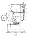
- FIG. 5 shows a schematic side view of a tubular bag machine according to the invention.
- This comprises a frame 5 designed as a housing, on the front 5a of which a vertical filling tube 6 is arranged.
- the upper area of the filling tube 6 is surrounded by a shaped shoulder 7, over which a sheet of enveloping material 8 is placed.
- the wrapping material 8 can be designed in the form of a film or a network and is pulled off a roll 9 which is mounted in the region of the housing 5.
- the covering material 8 is pulled off by means of endless belts 10, which are arranged in the area of the filling pipe 6 and have a large coefficient of friction, so that the covering material web is moved along the filling pipe 6.
- a longitudinal welding jaw 11 is provided underneath the shape shoulder 7 and is used to weld the edges of the enveloping material web, in order thus to form an endless hose.
- transverse welding jaws 1 which serve to subdivide the enveloping tube over, transverse seams into individual bags 12.
- the drive belt 10 is driven via a shaft 13, which is connected to a belt wheel 14, via which a drive belt 15 runs, which in turn is guided via a clutch 16. This is connected via a shaft 17 to a gear 18 and an angular gear 19 operatively connected to it. Via a gear transmission, not shown in detail, the drive is effected by the drive 3 (motor), which is not shown in FIG. 5.
- the filling tube 6 it is possible to fill the substances to be filled into the hose, the filling process generally only taking place when the cross-welding jaws 1 are in contact with the hose and squeeze it.
- FIG. 3 and 4 each show in detail the configuration of the drive for the cross-welding jaws 1 according to the invention.
- one of the cross-welding jaws 1 a is connected to a frame 20 which, guided by bearings 21, can be displaced transversely.
- An open state of the cross-welding jaw 1a is shown in solid lines in FIG. 3, while the closed state of the cross-welding jaw 1a and the frame 20 is shown with dashed lines.
- the other cross welding jaw 1b is connected to an actuating rod 22 which is guided laterally displaceably in a bearing 23.
- the solid lines again show an open state, while the closed state of the cross-welding jaw 1b is shown with dashed lines.
- Both the frame 20 and the actuating rod 22 are connected to a drive mechanism 4, which in the embodiment shown is designed in the form of a toggle lever mechanism which, as shown by the arrows, can be operated in a reversing manner.
- a drive mechanism 4 which in the embodiment shown is designed in the form of a toggle lever mechanism which, as shown by the arrows, can be operated in a reversing manner.
- FIG. 4 shows a side view of the arrangement of FIG. 3, the cross-welding jaws 1a and 1b being in the closed state, in contrast to FIG. 3.
- the frame 20 was shown in FIG. 4 just as little as its mounting 21.
- the shaft 24 is rotated via a gear 25 by the drive motor 3.
- the levers 26, 27 of the toggle lever mechanism 4 are each shown schematically in FIG. 4, each of which is connected to one another or to the frame and the actuating rod via joints 28 to 31 22 and the shaft 24 are connected.
- additional push-off elements in the form of elements which can be moved relative to one another above the cross-welding jaws 1 (as shown in FIG. 5) and which serve to squeeze the enveloping tube in order to prevent the substances to be filled in or falling out of the tube , while the cross welding jaws are in the preheating or post-heating position.
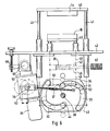
- FIG. 6 shows a schematic illustration of a further exemplary embodiment of the drive device of the cross-sealing jaws of the tubular bag machine according to the invention.
- the cross welding jaw 1a is on one Yoke 40 attached, which is connected to guides 41 which are slidably mounted on a frame 42.
- the free ends of the guides 41 are connected to one another via a cross member 43, on which a cam 44 is mounted, which can be designed, for example, in the form of a spherical head.
- the cross-welding jaw 1b is mounted on a yoke 45, which is connected to guides 46, which are also displaceably mounted on the frame 42.
- the guides 46 are connected at their free ends via a cross member 47.
- a spring element 39 which can be designed, for example, in the form of a hydraulic, mechanical or air spring.
- a cross member 48 is fastened, which is connected to two guides 49, the free ends of which are connected to a cross member 50.
- the device further comprises a carrier disk 34, on which two cam tracks 32, 33 are formed.
- the cam 51 can be moved in the cam track 33, while the cam 44 is guided in the cam track 32.
- the carrier disk 34 can be reversibly pivoted about a pivot axis 38. As can be seen from FIG. 6, pivoting of the carrier disk 34 leads to a movement of the cams 44 and 51 along the cam tracks 32 and 33 and thus to a reciprocating movement of the cross-welding jaws 1a and 1b.
- a pivoting of the carrier disk 34 is brought about by a drive motor 35 which is connected to a gear 52, on the output shaft of which one Crank disk 36 is flanged. This is pivotally connected to a rod 37, which is designed to be variable in length and is pivotably mounted at 53 on the carrier disk 34.
- the drive motor 35 is mounted on the frame 42 by means of a bearing plate 54 such that pivoting about a pivot axis 55 is possible.
- the drive motor 35 is pivoted about the pivot axis 55 by means of an adjustment mechanism 56, which can be actuated manually.
- an electric or hydraulic actuator By pivoting the drive motor 35, as shown in FIG. 6, the movement of the carrier disk 34 about the fixed pivot axis 38 can be changed in order to change the sealing time or the infeed time of the cross-welding jaws 1a, 1b, as also by changing the length the rod 37 is possible.
- the spring element 39 is operationally connected to a multi-way valve 57 and, for example in the case of an air spring, can be pressurized with compressed air in order to maintain or reduce the contact pressure of the cross-welding jaw 1b .
- FIG. 6 shows the individual pivoting states of the carrier disk 34 and the positions of the cams 51 and 44 as a function of the respective pivoting angles.
Landscapes
- Engineering & Computer Science (AREA)
- Mechanical Engineering (AREA)
- Physics & Mathematics (AREA)
- Thermal Sciences (AREA)
- Package Closures (AREA)
- Making Paper Articles (AREA)
Applications Claiming Priority (4)
| Application Number | Priority Date | Filing Date | Title |
|---|---|---|---|
| DE3835461 | 1988-10-18 | ||
| DE3835461 | 1988-10-18 | ||
| DE3907208 | 1989-03-07 | ||
| DE19893907208 DE3907208A1 (de) | 1988-10-18 | 1989-03-07 | Verfahren und vorrichtung zur steuerung der bewegung von querschweissbacken einer schlauchbeutelmaschine |
Related Child Applications (1)
| Application Number | Title | Priority Date | Filing Date |
|---|---|---|---|
| EP92104114.1 Division-Into | 1989-10-11 |
Publications (3)
| Publication Number | Publication Date |
|---|---|
| EP0368016A2 true EP0368016A2 (fr) | 1990-05-16 |
| EP0368016A3 EP0368016A3 (en) | 1990-08-29 |
| EP0368016B1 EP0368016B1 (fr) | 1994-06-08 |
Family
ID=25873357
Family Applications (1)
| Application Number | Title | Priority Date | Filing Date |
|---|---|---|---|
| EP19890118904 Expired - Lifetime EP0368016B1 (fr) | 1988-10-18 | 1989-10-11 | Machine de fabrication de sachets tubulaires |
Country Status (4)
| Country | Link |
|---|---|
| US (1) | US5117612A (fr) |
| EP (1) | EP0368016B1 (fr) |
| DE (2) | DE3907208A1 (fr) |
| ES (1) | ES2063797T3 (fr) |
Cited By (13)
| Publication number | Priority date | Publication date | Assignee | Title |
|---|---|---|---|---|
| EP0461689A1 (fr) * | 1990-06-07 | 1991-12-18 | EUROSICMA S.r.l. | Machine d'emballage pour le thermosoudage de film plastique à vitesse variable |
| EP0764584A3 (fr) * | 1995-09-23 | 1997-08-20 | Rovema Gmbh | Dispositif d'emballage |
| EP0835811A1 (fr) * | 1996-09-14 | 1998-04-15 | ISHIDA CO., Ltd. | Mécanisme de scellage transversal dans une machine à former, remplir et sceller des emballages |
| EP0945348A1 (fr) * | 1998-03-26 | 1999-09-29 | Rovema Verpackungsmaschinen GmbH | Machine de formage, remplissage et scellement d'emballages |
| EP1001186B1 (fr) * | 1995-09-23 | 2003-01-15 | Rovema Verpackungsmaschinen GmbH | Appareil pour déplacer des machoires de scellement |
| EP1600382A1 (fr) * | 2004-05-29 | 2005-11-30 | Rovema Verpackungsmaschinen GmbH | Dispositif pour le soudage d'un film mis en forme |
| EP1645401A3 (fr) * | 2004-10-09 | 2011-04-13 | Rovema Verpackungsmaschinen Gmbh | Procédé et dispositif pour positionner une machoire de soudage |
| WO2012152528A1 (fr) * | 2011-05-06 | 2012-11-15 | Robert Bosch Gmbh | Procédé de fonctionnement d'un dispositif de scellement par soudure transversale d'une ensacheuse verticale et dispositif de scellement par soudure transversale d'une ensacheuse verticale |
| EP2447043A3 (fr) * | 2010-11-02 | 2013-12-04 | Rovema GmbH | Procédé de scellement économe en énergie de sachets tubulaires |
| DE102012112918A1 (de) | 2012-12-21 | 2014-06-26 | Baumann Maschinenbau Solms Gmbh & Co. Kg | Schlauchbeutelmaschine |
| WO2018215261A1 (fr) * | 2017-05-23 | 2018-11-29 | Rovema Gmbh | Procédé de surveillance du fonctionnement d'une ensacheuse tubulaire |
| WO2018215258A1 (fr) * | 2017-05-23 | 2018-11-29 | Rovema Gmbh | Procédé de commande d'une ensacheuse tubulaire et ensacheuse tubulaire |
| WO2018215256A1 (fr) * | 2017-05-23 | 2018-11-29 | Rovema Gmbh | Procédé de vérification du fonctionnement d'une ensacheuse tubulaire |
Families Citing this family (28)
| Publication number | Priority date | Publication date | Assignee | Title |
|---|---|---|---|---|
| US5377474A (en) * | 1992-10-30 | 1995-01-03 | Hayssen Manufacturing Company | Form-fill-seal packaging apparatus |
| JP3473861B2 (ja) * | 1993-12-28 | 2003-12-08 | 株式会社イシダ | 包材の封止部に介在する介在物の有無の判定方法 |
| DE19535510B4 (de) * | 1995-09-25 | 2006-06-08 | Rovema - Verpackungsmaschinen Gmbh | Verschließvorrichtung für einen Verpackungsvorgang |
| DE19803838C2 (de) * | 1997-02-05 | 2000-05-25 | Rovema Gmbh | Verwendung eines Verfahrens zum Betreiben einer Schlauchbeutelmaschine zur Erkennung eines Produkteinschlusses |
| US5836136A (en) * | 1997-03-18 | 1998-11-17 | Kliklok Corporation | Seal integrity monitoring and adaptive control method and apparatus |
| US6006497A (en) * | 1997-03-26 | 1999-12-28 | Reichhold Chemicals, Inc. | Methods and apparatus for preparing a hot melt adhesive |
| US5912197A (en) * | 1997-08-21 | 1999-06-15 | C & H Packaging Company, Inc. | Thermal sealable plastic mesh web for automatic form, fill and seal machine |
| DE10102798B4 (de) * | 2001-01-22 | 2005-04-21 | Vaw Aluminium Ag | Verfahren zur Einstellung des Bearbeitungsablaufes bei der Herstellung von Siegelnähten |
| US6672038B2 (en) | 2001-03-02 | 2004-01-06 | Optima Machinery Corporation | Bag manipulating method and assembly for a bag filling station |
| US20020121074A1 (en) | 2001-03-02 | 2002-09-05 | Optima Machinery Corporation | Bag loading method and assembly for a bag filling station |
| US6761012B2 (en) | 2001-12-18 | 2004-07-13 | Atlanta Nisseki Claf, Inc. | Pre-prepared mesh-film web for use on form, fill and seal machines |
| DE10323163A1 (de) * | 2003-05-22 | 2004-12-09 | Rovema - Verpackungsmaschinen Gmbh | Vorrichtung zum Verschweißen einer umgeformten Folienbahn |
| DE10331360A1 (de) * | 2003-07-11 | 2005-01-27 | Rovema Verpackungsmaschinen Gmbh | Vorrichtung zum Verschweissen eines Folienschlauches |
| ITMI20031934A1 (it) * | 2003-10-08 | 2005-04-09 | Saldoflex S R L | Dispositivo di movimentazione del gruppo saldante, particolarmente per macchine per la fabbricazione di sacchi in plastica |
| DE102004043096B4 (de) * | 2004-09-07 | 2013-06-20 | Rovema Gmbh | Vorrichtung zum Verschweißen eines Folienschlauches |
| DE102004046972A1 (de) * | 2004-09-28 | 2006-04-13 | Rovema - Verpackungsmaschinen Gmbh | Verfahren und Vorrichtung zum Bewegen einer Schweißbacke |
| DE102005026219B4 (de) * | 2005-06-07 | 2007-12-13 | Poly-Clip System Gmbh & Co. Kg | Clipmaschine und Verfahren zum Einrichten einer Clipmaschine |
| EP1743837A1 (fr) * | 2005-07-14 | 2007-01-17 | CFS Weert B.V. | Machine de formage, remplissage et scellage de sacs avec des moyens de formage et/ou de scellage ajustables |
| DE102006014496A1 (de) | 2006-03-29 | 2007-10-04 | Robert Bosch Gmbh | Vorrichtung zum Befüllen von zumindest einer Dosierkammer |
| DE102006022946A1 (de) * | 2006-05-17 | 2007-11-22 | Rovema - Verpackungsmaschinen Gmbh | Vertikale Schlauchbeutelmaschine |
| DE102006023003A1 (de) * | 2006-05-17 | 2007-11-22 | Rovema Verpackungsmaschinen Gmbh | Vorrichtung mit zwei Schweißbacken |
| DE102006025831B4 (de) * | 2006-06-02 | 2013-10-31 | Rovema Gmbh | Vorrichtung zum Verschweißen von Kunststoff zu Verpackungszwecken (Torquemotor) |
| DE102007004140B4 (de) | 2007-01-26 | 2018-04-26 | Rovema Gmbh | Schlauchbeutelmaschine |
| DE102010019576B4 (de) * | 2010-05-05 | 2023-01-26 | Gea Food Solutions Germany Gmbh | Verpackungsmaschine mit einem auswechselbaren Antrieb der Hubeinrichtung |
| ITVR20110098A1 (it) * | 2011-05-11 | 2012-11-12 | P F M Spa | Macchina confezionatrice verticale di prodotti alimentari |
| US20140047802A1 (en) * | 2012-08-17 | 2014-02-20 | Khs Gmbh | Packaging machine |
| US10315789B2 (en) | 2012-11-20 | 2019-06-11 | Gram Equipment A/S | Sealing and cutting unit for a form fill seal machine |
| DE102017219948A1 (de) | 2017-01-12 | 2018-07-12 | Robert Bosch Gmbh | Vorrichtung zum Siegeln einer Verpackung |
Family Cites Families (25)
| Publication number | Priority date | Publication date | Assignee | Title |
|---|---|---|---|---|
| GB775061A (en) * | 1954-08-30 | 1957-05-15 | Grace W R & Co | Method and machine for forming fused seams in sheet thermoplastic material |
| US3055154A (en) * | 1957-11-04 | 1962-09-25 | Lynch Corp | Draw type wrapping machine |
| US3070931A (en) * | 1961-01-10 | 1963-01-01 | Gen Packaging Equip Co | Packaging machine |
| DE1179854B (de) * | 1962-07-14 | 1964-10-15 | Hamac Hansella Ag | Vorrichtung zum Abziehen und Querversiegeln eines auf einer Schlauchbeutelherstellungs-maschine geformten und portionweise gefuellten Schlauches aus siegel- oder schweissfaehigem Material |
| US3438173A (en) * | 1965-03-17 | 1969-04-15 | Shozo Omori | Method for automatically packaging solid articles and apparatus therefor |
| US3444732A (en) * | 1967-06-06 | 1969-05-20 | Albert L Robbins | Method and apparatus for determining optimum bonding parameters for thermoplastic material |
| US3685250A (en) * | 1970-07-09 | 1972-08-22 | Woodman Co | Cam interrupted sealing jaws for product stripping |
| US3826701A (en) * | 1972-10-31 | 1974-07-30 | Us Army | Controllable heat sealing process for optimum seal strength |
| US3925139A (en) * | 1974-01-10 | 1975-12-09 | Package Machinery Co | Seal monitoring apparatus |
| IT1018094B (it) * | 1974-07-10 | 1977-09-30 | Gd Spa | Dispositivo per la saldatura con trollata degli involucri di mate riale termoplastico particolarmente nelle macchine sovraincartatrici ad esempio di pacchetti di sigarette e simili |
| IT1075215B (it) * | 1976-12-02 | 1985-04-22 | Buitoni Perugina Ind Ibp | Apparecchio per la produzione di contenitori di imballaggio pressoche a parallele pipedo |
| US4291520A (en) * | 1979-12-26 | 1981-09-29 | Package Machinery Company | Vertical form, fill and seal packaging machine with improved end sealing and stripping means |
| US4585503A (en) * | 1982-10-12 | 1986-04-29 | Hauni-Werke Korber & Co. Kg. | Heat-treatment of wrappers in cigarette packing machines and the like |
| JPS60122548A (ja) * | 1983-12-05 | 1985-07-01 | 株式会社東芝 | 超音波診断装置 |
| JPH0330242Y2 (fr) * | 1984-11-27 | 1991-06-26 | ||
| JPH0423763Y2 (fr) * | 1984-11-27 | 1992-06-03 | ||
| CH666455A5 (de) * | 1985-02-18 | 1988-07-29 | Ilapak Res & Dev Sa | Verschliessvorrichtung an einer schlauchbeutelmaschine mit schweiss- und/oder siegelbacken. |
| US4603535A (en) * | 1985-05-28 | 1986-08-05 | Container Development Company | Portable sealing device |
| DE3538723C1 (de) * | 1985-10-31 | 1987-05-21 | Rovema Gmbh | Schlauchbeutelmaschine |
| DE3545228A1 (de) * | 1985-12-20 | 1987-07-02 | Rovema Gmbh | Verpackungsmaschine zum herstellen, fuellen und verschliessen von beuteln |
| US4757668A (en) * | 1986-01-27 | 1988-07-19 | Ilapak Research & Development S.A. | Method and apparatus for form-fill-seal packaging of articles |
| US4964944A (en) * | 1986-07-28 | 1990-10-23 | Baxter International Inc. | Apparatus for sealing and severing a web of film |
| US4751808A (en) * | 1987-04-09 | 1988-06-21 | Kliklok Corporation | Combined stripper and sealing apparatus for bag forming and method |
| DE3715838A1 (de) * | 1987-05-12 | 1988-12-01 | Rovema Gmbh | Antriebsverfahren und -system fuer schlauchbeutelmaschinen |
| US4768327A (en) * | 1987-06-22 | 1988-09-06 | Package Machinery Company | Packaging machine with variable sealing jaw displacement apparatus |
-
1989
- 1989-03-07 DE DE19893907208 patent/DE3907208A1/de active Granted
- 1989-10-11 ES ES89118904T patent/ES2063797T3/es not_active Expired - Lifetime
- 1989-10-11 EP EP19890118904 patent/EP0368016B1/fr not_active Expired - Lifetime
- 1989-10-11 DE DE58907828T patent/DE58907828D1/de not_active Expired - Fee Related
- 1989-10-13 US US07/421,468 patent/US5117612A/en not_active Expired - Lifetime
Cited By (19)
| Publication number | Priority date | Publication date | Assignee | Title |
|---|---|---|---|---|
| EP0461689A1 (fr) * | 1990-06-07 | 1991-12-18 | EUROSICMA S.r.l. | Machine d'emballage pour le thermosoudage de film plastique à vitesse variable |
| EP0764584A3 (fr) * | 1995-09-23 | 1997-08-20 | Rovema Gmbh | Dispositif d'emballage |
| EP1001186B1 (fr) * | 1995-09-23 | 2003-01-15 | Rovema Verpackungsmaschinen GmbH | Appareil pour déplacer des machoires de scellement |
| EP0835811A1 (fr) * | 1996-09-14 | 1998-04-15 | ISHIDA CO., Ltd. | Mécanisme de scellage transversal dans une machine à former, remplir et sceller des emballages |
| US6110089A (en) * | 1996-09-14 | 2000-08-29 | Ishida Co., Ltd. | Bag making and packaging machine |
| EP0945348A1 (fr) * | 1998-03-26 | 1999-09-29 | Rovema Verpackungsmaschinen GmbH | Machine de formage, remplissage et scellement d'emballages |
| EP1600382A1 (fr) * | 2004-05-29 | 2005-11-30 | Rovema Verpackungsmaschinen GmbH | Dispositif pour le soudage d'un film mis en forme |
| EP1645401A3 (fr) * | 2004-10-09 | 2011-04-13 | Rovema Verpackungsmaschinen Gmbh | Procédé et dispositif pour positionner une machoire de soudage |
| EP2447043A3 (fr) * | 2010-11-02 | 2013-12-04 | Rovema GmbH | Procédé de scellement économe en énergie de sachets tubulaires |
| WO2012152528A1 (fr) * | 2011-05-06 | 2012-11-15 | Robert Bosch Gmbh | Procédé de fonctionnement d'un dispositif de scellement par soudure transversale d'une ensacheuse verticale et dispositif de scellement par soudure transversale d'une ensacheuse verticale |
| DE102011075424B4 (de) | 2011-05-06 | 2023-06-15 | Syntegon Packaging Solutions B.V. | Verfahren zum Betreiben einer Quernahtsiegeleinrichtung in einer Schlauchbeutelmaschine und Quernahtsiegeleinrichtung in einer Schlauchbeutelmaschine |
| DE102012112918A1 (de) | 2012-12-21 | 2014-06-26 | Baumann Maschinenbau Solms Gmbh & Co. Kg | Schlauchbeutelmaschine |
| WO2018215261A1 (fr) * | 2017-05-23 | 2018-11-29 | Rovema Gmbh | Procédé de surveillance du fonctionnement d'une ensacheuse tubulaire |
| WO2018215258A1 (fr) * | 2017-05-23 | 2018-11-29 | Rovema Gmbh | Procédé de commande d'une ensacheuse tubulaire et ensacheuse tubulaire |
| DE102017208767A1 (de) | 2017-05-23 | 2018-11-29 | Rovema Gmbh | Verfahren zum Betrieb einer Schlauchbeutelmaschine und Schlauchbeutelmaschine |
| WO2018215256A1 (fr) * | 2017-05-23 | 2018-11-29 | Rovema Gmbh | Procédé de vérification du fonctionnement d'une ensacheuse tubulaire |
| US11370573B2 (en) | 2017-05-23 | 2022-06-28 | Rovema Gmbh | Method for testing the function of a tubular bag machine |
| US11383457B2 (en) | 2017-05-23 | 2022-07-12 | Rovema Gmbh | Method for operating a tubular bag machine and tubular bag machine |
| US11504919B2 (en) | 2017-05-23 | 2022-11-22 | Rovema Gmbh | Method for monitoring the function of a tubular bag machine |
Also Published As
| Publication number | Publication date |
|---|---|
| EP0368016B1 (fr) | 1994-06-08 |
| ES2063797T3 (es) | 1995-01-16 |
| DE3907208C2 (fr) | 1993-07-15 |
| EP0368016A3 (en) | 1990-08-29 |
| US5117612A (en) | 1992-06-02 |
| DE3907208A1 (de) | 1990-04-19 |
| DE58907828D1 (de) | 1994-07-14 |
Similar Documents
| Publication | Publication Date | Title |
|---|---|---|
| EP0368016B1 (fr) | Machine de fabrication de sachets tubulaires | |
| DE69423248T2 (de) | Vorrichtung zum Herstellen von Packungen | |
| DE69428717T2 (de) | Vorrichtung zum herstellen von matratzen und untermatratzengefügen | |
| EP0350617A2 (fr) | Procédé pour la fabrication, le remplissage et la fermeture d'emballages obtenu à partir d'une bande tubulaire et dispositif pour la mise en oeuvre du procédé | |
| DE69105248T2 (de) | Vorrichtung zum Versiegeln für eine Maschine zum Formen, Füllen und Schliessen von Packungen. | |
| DE2254877B2 (de) | Biegemaschine fuer draht- oder bandfoermiges material | |
| EP0489400A1 (fr) | Mécanisme racleur pour une machine d'emballage à fabriquer des manchons tubulaires | |
| DE4005078A1 (de) | Vorrichtung zum herstellen, fuellen und verschliessen von beuteln aus einem heissversiegelbaren band | |
| EP4029991B1 (fr) | Réglage de la course du dameur | |
| CH671729A5 (fr) | ||
| DE2509185A1 (de) | Verfahren zur herstellung aufblasbarer auskleidungen fuer stausaecke oder dergleichen und vorrichtung zur ausfuehrung des verfahrens | |
| DE102011075986A1 (de) | Verfahren zur energieeffizienten Siegelung von Schlauchbeuteln | |
| DE2023215B2 (de) | Rotationsreibschweissmaschine | |
| DE2331401C3 (de) | Maschine zum Banderolieren von Gegenständen | |
| DE29703924U1 (de) | Schlauchbeutelmaschine mit zumindest zwei Quersiegelbacken | |
| DE102007003930A1 (de) | Schlauchbeutelmaschine | |
| DE2644920A1 (de) | Nach dem abwaelzverfahren arbeitende maschine zum verzahnen von kegel- oder hypoid-zahnraedern | |
| DE2313208A1 (de) | Antriebsvorrichtung fuer eine formmaschine | |
| DE3334856A1 (de) | Antrieb fuer ein heizwerkzeug einer packmaschine | |
| DE2549129A1 (de) | Einrichtung fuer die gleichlaufsteuerung eines hin- und herbeweglichen werkzeugfuehrungsschlittens fuer fliegende scheren, stanzen und dergleichen werkzeugmaschinen | |
| EP3127683B1 (fr) | Poste de soudure destine a souder des sachets en film et procede associe | |
| DE2101232A1 (en) | Plastic welding - with pivoted lifter and curved pivoted welding pads to work all films | |
| DE1124419B (de) | Abzieh-, Siegel- und Schneidvorrichtung fuer Verpackungsmaschinen | |
| DE102007004140A1 (de) | Schlauchbeutelmaschine | |
| DE2328376C3 (de) | BeutelhersteHungsmaschine |
Legal Events
| Date | Code | Title | Description |
|---|---|---|---|
| PUAI | Public reference made under article 153(3) epc to a published international application that has entered the european phase |
Free format text: ORIGINAL CODE: 0009012 |
|
| AK | Designated contracting states |
Kind code of ref document: A2 Designated state(s): DE ES FR GB IT |
|
| PUAL | Search report despatched |
Free format text: ORIGINAL CODE: 0009013 |
|
| AK | Designated contracting states |
Kind code of ref document: A3 Designated state(s): DE ES FR GB IT |
|
| 17P | Request for examination filed |
Effective date: 19901002 |
|
| 17Q | First examination report despatched |
Effective date: 19911002 |
|
| GRAA | (expected) grant |
Free format text: ORIGINAL CODE: 0009210 |
|
| ITF | It: translation for a ep patent filed | ||
| AK | Designated contracting states |
Kind code of ref document: B1 Designated state(s): DE ES FR GB IT |
|
| XX | Miscellaneous (additional remarks) |
Free format text: TEILANMELDUNG 92104114.1 EINGEREICHT AM 11/10/89. |
|
| REF | Corresponds to: |
Ref document number: 58907828 Country of ref document: DE Date of ref document: 19940714 |
|
| RAP2 | Party data changed (patent owner data changed or rights of a patent transferred) |
Owner name: ROVEMA VERPACKUNGSMASCHINEN GMBH |
|
| GBT | Gb: translation of ep patent filed (gb section 77(6)(a)/1977) |
Effective date: 19940802 |
|
| ET | Fr: translation filed | ||
| REG | Reference to a national code |
Ref country code: ES Ref legal event code: FG2A Ref document number: 2063797 Country of ref document: ES Kind code of ref document: T3 |
|
| PLBE | No opposition filed within time limit |
Free format text: ORIGINAL CODE: 0009261 |
|
| STAA | Information on the status of an ep patent application or granted ep patent |
Free format text: STATUS: NO OPPOSITION FILED WITHIN TIME LIMIT |
|
| 26N | No opposition filed | ||
| PGFP | Annual fee paid to national office [announced via postgrant information from national office to epo] |
Ref country code: DE Payment date: 19970716 Year of fee payment: 9 |
|
| PG25 | Lapsed in a contracting state [announced via postgrant information from national office to epo] |
Ref country code: DE Free format text: LAPSE BECAUSE OF NON-PAYMENT OF DUE FEES Effective date: 19990803 |
|
| PGFP | Annual fee paid to national office [announced via postgrant information from national office to epo] |
Ref country code: GB Payment date: 20010914 Year of fee payment: 13 |
|
| PGFP | Annual fee paid to national office [announced via postgrant information from national office to epo] |
Ref country code: FR Payment date: 20011011 Year of fee payment: 13 |
|
| PGFP | Annual fee paid to national office [announced via postgrant information from national office to epo] |
Ref country code: ES Payment date: 20011024 Year of fee payment: 13 |
|
| REG | Reference to a national code |
Ref country code: GB Ref legal event code: IF02 |
|
| PG25 | Lapsed in a contracting state [announced via postgrant information from national office to epo] |
Ref country code: GB Free format text: LAPSE BECAUSE OF NON-PAYMENT OF DUE FEES Effective date: 20021011 |
|
| PG25 | Lapsed in a contracting state [announced via postgrant information from national office to epo] |
Ref country code: ES Free format text: LAPSE BECAUSE OF NON-PAYMENT OF DUE FEES Effective date: 20021012 |
|
| GBPC | Gb: european patent ceased through non-payment of renewal fee |
Effective date: 20021011 |
|
| PG25 | Lapsed in a contracting state [announced via postgrant information from national office to epo] |
Ref country code: FR Free format text: LAPSE BECAUSE OF NON-PAYMENT OF DUE FEES Effective date: 20030630 |
|
| REG | Reference to a national code |
Ref country code: FR Ref legal event code: ST |
|
| REG | Reference to a national code |
Ref country code: ES Ref legal event code: FD2A Effective date: 20031112 |
|
| PG25 | Lapsed in a contracting state [announced via postgrant information from national office to epo] |
Ref country code: IT Free format text: LAPSE BECAUSE OF NON-PAYMENT OF DUE FEES;WARNING: LAPSES OF ITALIAN PATENTS WITH EFFECTIVE DATE BEFORE 2007 MAY HAVE OCCURRED AT ANY TIME BEFORE 2007. THE CORRECT EFFECTIVE DATE MAY BE DIFFERENT FROM THE ONE RECORDED. Effective date: 20051011 |