EP0368021A1 - Balai-ramasseur à gazon - Google Patents
Balai-ramasseur à gazon Download PDFInfo
- Publication number
- EP0368021A1 EP0368021A1 EP89118937A EP89118937A EP0368021A1 EP 0368021 A1 EP0368021 A1 EP 0368021A1 EP 89118937 A EP89118937 A EP 89118937A EP 89118937 A EP89118937 A EP 89118937A EP 0368021 A1 EP0368021 A1 EP 0368021A1
- Authority
- EP
- European Patent Office
- Prior art keywords
- brush elements
- brush
- tube
- rotation
- brackets
- Prior art date
- Legal status (The legal status is an assumption and is not a legal conclusion. Google has not performed a legal analysis and makes no representation as to the accuracy of the status listed.)
- Granted
Links
Images



Classifications
-
- A—HUMAN NECESSITIES
- A01—AGRICULTURE; FORESTRY; ANIMAL HUSBANDRY; HUNTING; TRAPPING; FISHING
- A01B—SOIL WORKING IN AGRICULTURE OR FORESTRY; PARTS, DETAILS, OR ACCESSORIES OF AGRICULTURAL MACHINES OR IMPLEMENTS, IN GENERAL
- A01B33/00—Tilling implements with rotary driven tools, e.g. in combination with fertiliser distributors or seeders, with grubbing chains, with sloping axles, with driven discs
- A01B33/08—Tools; Details, e.g. adaptations of transmissions or gearings
- A01B33/14—Attaching the tools to the rotating shaft, e.g. resiliently or flexibly-attached tools
- A01B33/142—Attaching the tools to the rotating shaft, e.g. resiliently or flexibly-attached tools the rotating shaft being oriented horizontally
- A01B33/144—Attaching the tools to the rotating shaft, e.g. resiliently or flexibly-attached tools the rotating shaft being oriented horizontally with spring tools or resiliently-attached rigid tools
-
- A—HUMAN NECESSITIES
- A01—AGRICULTURE; FORESTRY; ANIMAL HUSBANDRY; HUNTING; TRAPPING; FISHING
- A01D—HARVESTING; MOWING
- A01D43/00—Mowers combined with apparatus performing additional operations while mowing
- A01D43/02—Mowers combined with apparatus performing additional operations while mowing with rakes
-
- E—FIXED CONSTRUCTIONS
- E01—CONSTRUCTION OF ROADS, RAILWAYS, OR BRIDGES
- E01H—STREET CLEANING; CLEANING OF PERMANENT WAYS; CLEANING BEACHES; DISPERSING OR PREVENTING FOG IN GENERAL CLEANING STREET OR RAILWAY FURNITURE OR TUNNEL WALLS
- E01H1/00—Removing undesirable matter from roads or like surfaces, with or without moistening of the surface
- E01H1/02—Brushing apparatus, e.g. with auxiliary instruments for mechanically loosening dirt
- E01H1/05—Brushing apparatus, e.g. with auxiliary instruments for mechanically loosening dirt with driven brushes
- E01H1/056—Brushing apparatus, e.g. with auxiliary instruments for mechanically loosening dirt with driven brushes having horizontal axes
Definitions
- the invention relates to a device for sweeping surfaces and for mowing lawns according to the preamble of claim 1.
- German Offenlegungsschrift 36 29 746 It has already been proposed by German Offenlegungsschrift 36 29 746 to readjust the entire rotor via an adjustment mechanism in such a way that the rotational diameter of the outer parts of the brush elements, which is reduced due to wear, can be compensated for.
- this type is very complex and expensive.
- the invention is based on the object, in the simplest way, to compensate for the rotation radius which has become smaller due to wear of the brush elements in a device of the type described at the outset.
- the mounting tube has a non-circular cross-section, wherein in the circumference of the mounting tube seen with different radial distances from the axis of rotation of the sweeping brush holders for the brush elements are attached.
- the support tube can have an oval cross section or a polygonal cross section that resembles a compressed polygon. It is provided according to the invention that a polygonal, preferably octagonal, support tube is provided which is symmetrical in cross section.
- the support tube can also be octagonal in cross-section and approximated to an ellipse, but with a straight surface.
- the invention provides that two each opposite sides of the support tube, the brush elements are attached to the support tube by means of brackets. Furthermore, it is provided according to the invention that two brackets are arranged next to one another, as seen in the circumferential direction, on the surfaces of the mounting tube which are most distant from the axis of rotation. This creates the prerequisite that brush elements and scarifying knives are to be arranged simultaneously on the same rotor. The brush elements, preferably new brush elements, are then attached to the brackets closest to the axis of rotation, while the scarifying knives are attached to the brackets furthest away. This solves the collection of the lawn and other parts removed from the lawns by the scarifying knives in the collecting container, as well as an excellent reversal of these parts just removed from the ground by the scarifying knives and the collecting by the brush elements.
- the brush elements are interchangeable with the knife elements, and can also be used at the same time, becomes a universally usable machine which can sweep or scarify separately or at the same time and can mow surfaces.
- mowing knives can also be used in conjunction with the brush elements, so that when the lawn is mowed, the lawn is also swept and the crop is collected.
- brackets In order to simplify the attachment of the brush elements to the brackets with the greatest radial distance from the axis of rotation of the mounting tube, it is provided according to the invention that separate brackets are attached to the rotary drum for the knives and for the brush elements.
- the brush elements which are subject to wear can be arranged in the simplest way on the corresponding holders at different radial distances from the axis of rotation of the holder tube.
- the arrangement of the brush elements on the brackets arranged at different radial distances from the axis of rotation of the mounting tube ensures that the radius of rotation between the axis of rotation and the orbit of the brush elements of different lengths always remains the same.
- the sweeping or the mown and / or scarified material from the lawn is collected in a satisfactory manner, since the distance between the orbit of the brush elements and the baffle plate of the material conveying channel and the surface of the surface to be swept remains approximately constant, so that the Good picked up by the brush elements reaches the inside of the groupage container in a proper manner via the material conveying channel and good sweeping work of the brush elements is achieved on the floor surface.
- the knives are fastened with intermediate members to the holders attached to the rotary drum, and that these intermediate members remain on the rotary drum when the brush elements are arranged on the rotary drum.
- the disassembly of the intermediate links with which the knives are fastened to the brackets of the rotary drum is now eliminated in a particularly advantageous manner. It is now only necessary to remove the knives, which can be assembled or disassembled on the intermediate links without tools, from the intermediate links. Thereafter, the brush elements can then be very easily attached to the holders provided for the brush elements and adjacent to the holders for the knife elements.
- the device for sweeping surfaces and / or for mowing or scarifying lawn surfaces has the movable frame 1, the drive housing 2 with the rotating body 3 and the pivotable support wheels 4 and the likewise pivotable trailing wheels 5.
- the groupage container 6 is fastened in such a way that it can be pivoted about the pivot axis 7 for emptying the groupage container 6, so that the materials located in the groupage container 6 via the emptying opening 8 located in the upper region of the container 6, for example, on a Have trailer overloaded.
- This pivoting of the groupage container 6 about the pivot axis 7 takes place through the two hydraulic cylinders 9, which are connected via hydraulic lines 9 to the hydraulic system of the tractor pulling the device in the direction of travel 10.
- the setting of the working depth between the working tools 11 arranged on the rotary body 3, which are designed, for example, as brush elements 12, and the bottom surface 13 is carried out by means of the hydraulic cylinder 14.
- This setting element which is designed as a hydraulic cylinder 14, for setting the working depth, that is, the distance of the orbit 15 on the rotating body 3, which is designed as a mounting tube 16, arranged brush elements 12 and the bottom surface 13, is arranged between the frame 1 of the device and the pivotable trailing wheels 5, the trailing wheels 5 in turn being fastened to the pivotable handlebar frame 17.
- the hydraulic cylinder 14 is pivotally mounted on the side of the working piston 18 on the bracket 19 fastened to the frame 1, the cylinder 20 of the hydraulic cylinder 14 being mounted on the pivotable handlebar frame 17 via the bracket 21.
- the pivotable handlebar frame 17 is connected to the drive housing 2 for the rotating body 3 via the strut 22.
- the inclination of the frame 1 with respect to the floor surface 13, ie the working depth of the work tools 11, can be adjusted by means of the hydraulic cylinder 14, which takes over the guidance of the pivotable handlebar frame in such a way that the handlebar frame 17 about axes 23 lying transversely to the direction of travel 10 and not with respect to it Hydraulic cylinder 14 is pivoted.
- the guide element 24 is arranged between the pivotable handlebar frame 17 and the hydraulic cylinder 14.
- Such a hydraulic cylinder 14, which is arranged to adjust the working depth between the handlebar frame 17 and the frame of the device 1, is located in the respective outer area of the device.
- the height between the bottom surface 13 and the pivot axis 7 can vary, this distance being increased when the hydraulic cylinder 14 is extended and the discharge height when the container 6 is emptied is also increased, so that the goods received in the groupage container 6 can also be transferred to trailers with a large loading area.
- the distance between the orbit 15 of the working tools 11, which are designed as brush elements 12 and are arranged on the rotating body 3, and the baffle plate 25 has an approximately constant distance from one another. This is necessary so that the material is precisely collected by means of the working tools 11 arranged on the rotating body 3, the rotating body 3 in Direction of rotation 26 is driven, and the goods to be picked up via the goods conveying channel 27 into the groupage container 6 is guaranteed.
- the mounting tube 16 Since the brush elements 12 are subject to wear, so that the radius of rotation 28 of the orbits 15 of the brush elements 12 is reduced, the mounting tube 16 has a non-circular cross-section, so that on the circumference of the mounting tube 16 with different radial distances from the axis of rotation 29 of the mounting tube 16, the Brackets 30 for the work tools 11, which can be designed as brush elements 12, are attached.
- the brush elements 12 are each fastened on two opposite sides of the holder tube 16 by means of the holders 30 to the holder tube 16.
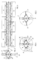
- FIG. 4 shows the arrangement of the brush elements 12, which are of different lengths due to wear, on the respective holders 30 of the holder tube 16.
- the arrangement of the brush elements 12, which have become shorter due to wear, at different radial distances from the axis of rotation 29 of the mounting tube 16 ensures that the distance between the orbit 15 of the brush elements 12 and the baffle plate 25 of the material conveying channel 27 remains approximately constant, so that the brush elements 12 picked up goods get into the interior of the groupage container 6 in a proper manner via the goods conveying channel 27 and good sweeping work of the brush elements 12 on the floor surface 13 is achieved.
- FIG. 5 shows the simultaneous arrangement of scarifying knives 32 and brush elements 12 on the holder tube 16 of the rotary body 3.
- the brush elements 12 are arranged on the holders 30 attached closer to the axis of rotation 29, while the knives 32 on the further from the axis of rotation 29 of the rotary body 3 attached brackets 30 are attached. If the brush elements 12 are worn, so that their outer edge 33 is too far apart from the prescribed rotation radius 28 of the orbits 15, according to FIG. 4, on the other holders 30, which are at a greater distance from the axis of rotation 29 of the rotating body 3, arrange. It is then also possible to attach the mowing and / or scarifying knife 32 and the brush elements 12 to the holders 30, which are arranged on the surfaces 31 of the rotary body 3.
- the device for sweeping surfaces and / or for mowing or scarifying lawn areas Fig. 6 also has the movable frame 1, the drive housing 2 with the rotating body 3 and the pivoting support wheels 4 and the likewise pivotable trailing wheels 5.
- the groupage container 6 is fastened such that it can be pivoted about the pivot axis 7 for emptying the groupage container 6, so that the Groupage material container 6 can be loaded onto a trailer, for example, via the emptying opening 8 located in the upper region of the container 6.
- This pivoting of the groupage container 6 about the pivot axis 7 is carried out by the two hydraulic cylinders 9, which are connected via hydraulic lines to the hydraulic system of the tractor pulling the device in the direction of travel 10.
- the setting of the working depth between the working tools 11 arranged on the rotary body 3, which are designed, for example, as brush elements 12, and the bottom surface 13 is carried out by means of the hydraulic cylinder 14.
- This setting element designed as a hydraulic cylinder 14, for setting the working depth, that is to say the distance between the orbit 15 on the rotating body 3, which is designed as a mounting tube 16, arranged brush elements 12 and the bottom surface 13, is arranged between the frame 1 of the device and the pivotable trailing wheels 5, the trailing wheels 5 in turn being fastened to the pivotable handlebar frame 17.
- the hydraulic cylinder 14 is pivotally mounted on the side of the working piston 18 on the bracket 19 fastened to the frame 1, the cylinder 20 of the hydraulic cylinder 14 being mounted on the pivotable handlebar frame 17 via the bracket 21.
- the pivotable handlebar frame 17 is connected to the drive housing 2 for the rotating body 3 via the strut 22.
- the inclination of the frame 1 relative to the floor surface 13, ie the working depth of the work tools 11, can be adjusted by means of the hydraulic cylinder 14, which takes over the guiding of the pivotable handlebar frame in such a way that the handlebar frame 17 about axes 23 lying transversely to the direction of travel 10 and not opposite the one Hydraulic cylinder 14 is pivoted.
- the guide element 24 is arranged between the pivotable handlebar frame 17 and the hydraulic cylinder 14.
- a Such hydraulic cylinder 14, which is arranged for adjusting the working depth between the handlebar frame 17 and the frame of the device 1, is located in the respective outer area of the device.
- the height between the bottom surface 13 and the pivot axis 7 can vary, this distance being increased when the hydraulic cylinder 14 is extended and the discharge height when the container 6 is emptied is also increased, so that the goods received in the groupage container 6 can also be transferred to trailers with a large loading area.
- the distance between the orbit 15 of the working tools 11, which are designed as brush elements 12 and are arranged on the rotating body 3, and the baffle plate 25 has an approximately constant distance from one another. This is necessary so that an exact collection of the material is ensured by means of the working tools 11 arranged on the rotating body 3, the rotating body 3 being driven in the direction of rotation 26, and the material to be picked up reaching the collecting material container 6 via the material conveying channel 27.
- the mounting tube 16 Since the brush elements 12 are subject to wear, so that the radius of rotation 28 of the orbits 15 of the brush elements 12 is reduced, the mounting tube 16 has a non-circular cross-section, so that on the circumference of the mounting tube 16 with different radial distances from the axis of rotation 29 of the mounting tube 16, the Brackets 30 for the work tools 11, which can be designed as brush elements 12, are attached.
- the brush elements 12 are each fastened on two opposite sides of the holder tube 16 by means of the holders 30 to the holder tube 16.
- FIG. 9 shows the arrangement of additional scarifying knives 32 next to the brush elements 12 on the brackets 30 of the holding tube 16.
- the scarifying knives 32 are arranged on the most distant surfaces 34 from the axis of rotation 29, with each of these surfaces 34 of the holding tube 16 three brackets 30 are arranged side by side seen in the circumferential direction of the support tube 16.
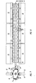
- the working tools 11 designed as mowing and / or scarifying knives 32 are fastened to the brackets 30 welded to the rotating body 3 by means of the intermediate members 35.
- These mowing and / or scarifying knives 32 can be assembled or disassembled on the intermediate members 35 without tools.
- Fig. 11 shows the arrangement of worn, shorter brush elements 12 on the most distant from the axis of rotation 29 brackets 30 on the mounting tube 16. Because the brackets 30 for the brush elements 12 at different radial distances from the axis of rotation 29 on the circumference of the mounting tube 16 are arranged, it is ensured that the radius of rotation 28 between the axis of rotation 29 and the orbit 15 always remains the same with brush elements 12 of different lengths.
- the arrangement of the brush elements 12, which have become shorter due to wear, at different radial distances from the axis of rotation 29 of the mounting tube 16 ensures that the distance between the orbit 15 of the brush elements 12 and the baffle plate 25 of the material conveying channel 27 remains approximately constant, so that the brush elements 12 picked up goods get into the interior of the groupage container 6 in a proper manner via the material conveying channel 27 and good sweeping work of the brush elements 12 on the floor surface 13 is achieved.
- this is the holder 30 for the respective brush element 12 Adjacent scarifier 32 removed from the intermediate member 35 so that the brush member 12 can move freely in its holder 30.
- the assembly of the brush elements 12 can be carried out in the simplest way, since only the mowing and / or scarifying knives 32 of the adjacent holders have to be removed, the intermediate members 35 remaining on the holding tube 16.
Landscapes
- Life Sciences & Earth Sciences (AREA)
- Engineering & Computer Science (AREA)
- Environmental Sciences (AREA)
- Architecture (AREA)
- Civil Engineering (AREA)
- Structural Engineering (AREA)
- Mechanical Engineering (AREA)
- Soil Sciences (AREA)
- Harvester Elements (AREA)
Applications Claiming Priority (4)
| Application Number | Priority Date | Filing Date | Title |
|---|---|---|---|
| DE19883837939 DE3837939A1 (de) | 1988-11-09 | 1988-11-09 | Geraet fuer das kehren von flaechen und/oder zum maehen von rasenflaechen |
| DE3837939 | 1988-11-09 | ||
| DE3909163 | 1989-03-21 | ||
| DE3909163A DE3909163A1 (de) | 1988-11-09 | 1989-03-21 | Geraet fuer das kehren von flaechen und/oder zum maehen von rasenflaechen |
Publications (2)
| Publication Number | Publication Date |
|---|---|
| EP0368021A1 true EP0368021A1 (fr) | 1990-05-16 |
| EP0368021B1 EP0368021B1 (fr) | 1992-01-08 |
Family
ID=25874049
Family Applications (1)
| Application Number | Title | Priority Date | Filing Date |
|---|---|---|---|
| EP89118937A Expired - Lifetime EP0368021B1 (fr) | 1988-11-09 | 1989-10-12 | Balai-ramasseur à gazon |
Country Status (2)
| Country | Link |
|---|---|
| EP (1) | EP0368021B1 (fr) |
| DE (2) | DE3909163A1 (fr) |
Cited By (4)
| Publication number | Priority date | Publication date | Assignee | Title |
|---|---|---|---|---|
| DE4016154A1 (de) * | 1990-05-21 | 1991-11-28 | Sobernheimer Maschinenbau Gmbh | Selbstaufnehmende vorbaukehrvorrichtung |
| EP0464809A1 (fr) * | 1990-07-05 | 1992-01-08 | Ignacio Rodenas Olivares | Tondeuse à gazon-balayeuse |
| CN103215903A (zh) * | 2013-03-19 | 2013-07-24 | 林淑琴 | 一种道路清扫车 |
| CN112127306A (zh) * | 2020-10-28 | 2020-12-25 | 蒋小春 | 一种便于安装的多功能车载式道路清扫装置 |
Citations (8)
| Publication number | Priority date | Publication date | Assignee | Title |
|---|---|---|---|---|
| DE89465C (fr) * | ||||
| DE1658398A1 (de) * | 1967-09-18 | 1970-10-22 | Kehrmaschinenfabrik Mueller & | Aufnahmekehrwalze mit Laufraedern |
| FR2229374A1 (en) * | 1973-05-14 | 1974-12-13 | Charpenet Louis Joseph | Tractor drawn mechanical sweeping machine - rotary broom can be compensated fof wear, front lifts for transportation |
| FR2438965A1 (fr) * | 1978-10-17 | 1980-05-16 | Champenois Ets | Perfectionnements aux machines a tondre, broyer et ramasser |
| GB1588530A (en) * | 1978-05-22 | 1981-04-23 | Smalley Eng Ltd Richard | Herbage cutting machine |
| DE8704846U1 (de) * | 1986-04-05 | 1987-06-25 | Amazonen-Werke H. Dreyer Gmbh & Co Kg, 4507 Hasbergen | Mähmaschine u. dgl. |
| DE3629746A1 (de) * | 1986-09-01 | 1988-03-03 | Wiedenmann Gmbh | Geraet fuer das kehren von flaechen |
| DE3707093A1 (de) * | 1987-02-27 | 1988-09-08 | Dieter Gruenig | Kehrmaschine |
-
1989
- 1989-03-21 DE DE3909163A patent/DE3909163A1/de not_active Ceased
- 1989-10-12 DE DE8989118937T patent/DE58900702D1/de not_active Expired - Lifetime
- 1989-10-12 EP EP89118937A patent/EP0368021B1/fr not_active Expired - Lifetime
Patent Citations (8)
| Publication number | Priority date | Publication date | Assignee | Title |
|---|---|---|---|---|
| DE89465C (fr) * | ||||
| DE1658398A1 (de) * | 1967-09-18 | 1970-10-22 | Kehrmaschinenfabrik Mueller & | Aufnahmekehrwalze mit Laufraedern |
| FR2229374A1 (en) * | 1973-05-14 | 1974-12-13 | Charpenet Louis Joseph | Tractor drawn mechanical sweeping machine - rotary broom can be compensated fof wear, front lifts for transportation |
| GB1588530A (en) * | 1978-05-22 | 1981-04-23 | Smalley Eng Ltd Richard | Herbage cutting machine |
| FR2438965A1 (fr) * | 1978-10-17 | 1980-05-16 | Champenois Ets | Perfectionnements aux machines a tondre, broyer et ramasser |
| DE8704846U1 (de) * | 1986-04-05 | 1987-06-25 | Amazonen-Werke H. Dreyer Gmbh & Co Kg, 4507 Hasbergen | Mähmaschine u. dgl. |
| DE3629746A1 (de) * | 1986-09-01 | 1988-03-03 | Wiedenmann Gmbh | Geraet fuer das kehren von flaechen |
| DE3707093A1 (de) * | 1987-02-27 | 1988-09-08 | Dieter Gruenig | Kehrmaschine |
Cited By (4)
| Publication number | Priority date | Publication date | Assignee | Title |
|---|---|---|---|---|
| DE4016154A1 (de) * | 1990-05-21 | 1991-11-28 | Sobernheimer Maschinenbau Gmbh | Selbstaufnehmende vorbaukehrvorrichtung |
| EP0464809A1 (fr) * | 1990-07-05 | 1992-01-08 | Ignacio Rodenas Olivares | Tondeuse à gazon-balayeuse |
| CN103215903A (zh) * | 2013-03-19 | 2013-07-24 | 林淑琴 | 一种道路清扫车 |
| CN112127306A (zh) * | 2020-10-28 | 2020-12-25 | 蒋小春 | 一种便于安装的多功能车载式道路清扫装置 |
Also Published As
| Publication number | Publication date |
|---|---|
| EP0368021B1 (fr) | 1992-01-08 |
| DE3909163A1 (de) | 1990-09-27 |
| DE58900702D1 (de) | 1992-02-20 |
Similar Documents
| Publication | Publication Date | Title |
|---|---|---|
| DE7413508U (de) | Steinbrechvorrichtung | |
| DE19642788C1 (de) | Räumkehraggregat zum Frontanbau an ein Trägerfahrzeug | |
| DE69324838T2 (de) | Mähmaschine für Gewächs | |
| DE3854929T2 (de) | Bodenbearbeitungsmaschine mit verbessertem Stabilisierungsorgan | |
| DE4319729C2 (de) | Kehrgerät | |
| DE19715435C2 (de) | Überkopfwerfer-Reinigungsmaschine | |
| EP0368021B1 (fr) | Balai-ramasseur à gazon | |
| DE2210689A1 (de) | Maschine zum versaeubern von fahrbahnraendern | |
| DE29719508U1 (de) | Anbau-Kehrvorrichtung mit Aufnahmeeinrichtung | |
| EP0065782A1 (fr) | Unité de récolte en files pour têtes de récolte de récolteuses pour denrées arrangées en files | |
| EP0391010A1 (fr) | Balayeuse | |
| EP0368019B1 (fr) | Appareil à tondre et aérer le gazon | |
| EP0646676B1 (fr) | Dispositif d'entretien avec support réglable en hauteur pour une brosse cylindrique | |
| CH638076A5 (de) | Bodenbearbeitungsmaschine. | |
| DE3837939A1 (de) | Geraet fuer das kehren von flaechen und/oder zum maehen von rasenflaechen | |
| DE3042510A1 (de) | Zum absaugen von organischen abfaellen u.dgl. von strassenraendern, banketten, graeben und boeschungen dienendes sauggeraet | |
| DE3837937A1 (de) | Geraet zum maehen und vertikutieren von rasenflaechen | |
| EP3825465A1 (fr) | Balayeuse automatique permettant de nettoyer des surfaces de sol routières ou piétonnes | |
| EP0685148A1 (fr) | Machine à faucher et/ou à aérer | |
| EP0992629B1 (fr) | Dispositif pour enlever mécaniquement des mauvaises herbes | |
| DE3107840A1 (de) | "vorbau-strassenkehrmaschine" | |
| DE19537094C2 (de) | Vorrichtung zum Sammeln von Golfbällen | |
| EP0129047B1 (fr) | Machine agricole pour le travail du sol comportant un rotor équipé de dents | |
| EP0259556B1 (fr) | Machine de fenaison | |
| DE102012005544A1 (de) | "Mähmaschine mit einem Mähbalken" |
Legal Events
| Date | Code | Title | Description |
|---|---|---|---|
| PUAI | Public reference made under article 153(3) epc to a published international application that has entered the european phase |
Free format text: ORIGINAL CODE: 0009012 |
|
| AK | Designated contracting states |
Kind code of ref document: A1 Designated state(s): CH DE FR GB IT LI NL SE |
|
| 17P | Request for examination filed |
Effective date: 19900423 |
|
| 17Q | First examination report despatched |
Effective date: 19910613 |
|
| GRAA | (expected) grant |
Free format text: ORIGINAL CODE: 0009210 |
|
| ITF | It: translation for a ep patent filed | ||
| AK | Designated contracting states |
Kind code of ref document: B1 Designated state(s): CH DE FR GB IT LI NL SE |
|
| ET | Fr: translation filed | ||
| GBT | Gb: translation of ep patent filed (gb section 77(6)(a)/1977) | ||
| REF | Corresponds to: |
Ref document number: 58900702 Country of ref document: DE Date of ref document: 19920220 |
|
| PLBE | No opposition filed within time limit |
Free format text: ORIGINAL CODE: 0009261 |
|
| STAA | Information on the status of an ep patent application or granted ep patent |
Free format text: STATUS: NO OPPOSITION FILED WITHIN TIME LIMIT |
|
| 26N | No opposition filed | ||
| PGFP | Annual fee paid to national office [announced via postgrant information from national office to epo] |
Ref country code: CH Payment date: 19931020 Year of fee payment: 5 |
|
| PGFP | Annual fee paid to national office [announced via postgrant information from national office to epo] |
Ref country code: SE Payment date: 19931028 Year of fee payment: 5 |
|
| PG25 | Lapsed in a contracting state [announced via postgrant information from national office to epo] |
Ref country code: SE Effective date: 19941013 |
|
| PG25 | Lapsed in a contracting state [announced via postgrant information from national office to epo] |
Ref country code: LI Effective date: 19941031 Ref country code: CH Effective date: 19941031 |
|
| EAL | Se: european patent in force in sweden |
Ref document number: 89118937.5 |
|
| REG | Reference to a national code |
Ref country code: CH Ref legal event code: PL |
|
| EUG | Se: european patent has lapsed |
Ref document number: 89118937.5 |
|
| PGFP | Annual fee paid to national office [announced via postgrant information from national office to epo] |
Ref country code: GB Payment date: 19970715 Year of fee payment: 9 |
|
| PGFP | Annual fee paid to national office [announced via postgrant information from national office to epo] |
Ref country code: NL Payment date: 19971031 Year of fee payment: 9 |
|
| PG25 | Lapsed in a contracting state [announced via postgrant information from national office to epo] |
Ref country code: GB Free format text: LAPSE BECAUSE OF NON-PAYMENT OF DUE FEES Effective date: 19981012 |
|
| PG25 | Lapsed in a contracting state [announced via postgrant information from national office to epo] |
Ref country code: NL Free format text: LAPSE BECAUSE OF NON-PAYMENT OF DUE FEES Effective date: 19990501 |
|
| GBPC | Gb: european patent ceased through non-payment of renewal fee |
Effective date: 19981012 |
|
| NLV4 | Nl: lapsed or anulled due to non-payment of the annual fee |
Effective date: 19990501 |
|
| PGFP | Annual fee paid to national office [announced via postgrant information from national office to epo] |
Ref country code: FR Payment date: 19991029 Year of fee payment: 11 |
|
| PG25 | Lapsed in a contracting state [announced via postgrant information from national office to epo] |
Ref country code: FR Free format text: LAPSE BECAUSE OF NON-PAYMENT OF DUE FEES Effective date: 20010629 |
|
| REG | Reference to a national code |
Ref country code: FR Ref legal event code: ST |
|
| PGFP | Annual fee paid to national office [announced via postgrant information from national office to epo] |
Ref country code: DE Payment date: 20011026 Year of fee payment: 13 |
|
| PG25 | Lapsed in a contracting state [announced via postgrant information from national office to epo] |
Ref country code: DE Free format text: LAPSE BECAUSE OF NON-PAYMENT OF DUE FEES Effective date: 20030501 |
|
| PG25 | Lapsed in a contracting state [announced via postgrant information from national office to epo] |
Ref country code: IT Free format text: LAPSE BECAUSE OF NON-PAYMENT OF DUE FEES;WARNING: LAPSES OF ITALIAN PATENTS WITH EFFECTIVE DATE BEFORE 2007 MAY HAVE OCCURRED AT ANY TIME BEFORE 2007. THE CORRECT EFFECTIVE DATE MAY BE DIFFERENT FROM THE ONE RECORDED. Effective date: 20051012 |