EP0368037A1 - Procédé de commande de la distribution du taux d'évaporation produite par un faisceau d'électrons - Google Patents
Procédé de commande de la distribution du taux d'évaporation produite par un faisceau d'électrons Download PDFInfo
- Publication number
- EP0368037A1 EP0368037A1 EP89119229A EP89119229A EP0368037A1 EP 0368037 A1 EP0368037 A1 EP 0368037A1 EP 89119229 A EP89119229 A EP 89119229A EP 89119229 A EP89119229 A EP 89119229A EP 0368037 A1 EP0368037 A1 EP 0368037A1
- Authority
- EP
- European Patent Office
- Prior art keywords
- control
- correction
- variable
- grid
- memory
- Prior art date
- Legal status (The legal status is an assumption and is not a legal conclusion. Google has not performed a legal analysis and makes no representation as to the accuracy of the status listed.)
- Granted
Links
Images


Classifications
-
- C—CHEMISTRY; METALLURGY
- C23—COATING METALLIC MATERIAL; COATING MATERIAL WITH METALLIC MATERIAL; CHEMICAL SURFACE TREATMENT; DIFFUSION TREATMENT OF METALLIC MATERIAL; COATING BY VACUUM EVAPORATION, BY SPUTTERING, BY ION IMPLANTATION OR BY CHEMICAL VAPOUR DEPOSITION, IN GENERAL; INHIBITING CORROSION OF METALLIC MATERIAL OR INCRUSTATION IN GENERAL
- C23C—COATING METALLIC MATERIAL; COATING MATERIAL WITH METALLIC MATERIAL; SURFACE TREATMENT OF METALLIC MATERIAL BY DIFFUSION INTO THE SURFACE, BY CHEMICAL CONVERSION OR SUBSTITUTION; COATING BY VACUUM EVAPORATION, BY SPUTTERING, BY ION IMPLANTATION OR BY CHEMICAL VAPOUR DEPOSITION, IN GENERAL
- C23C14/00—Coating by vacuum evaporation, by sputtering or by ion implantation of the coating forming material
- C23C14/22—Coating by vacuum evaporation, by sputtering or by ion implantation of the coating forming material characterised by the process of coating
- C23C14/24—Vacuum evaporation
- C23C14/28—Vacuum evaporation by wave energy or particle radiation
- C23C14/30—Vacuum evaporation by wave energy or particle radiation by electron bombardment
-
- C—CHEMISTRY; METALLURGY
- C23—COATING METALLIC MATERIAL; COATING MATERIAL WITH METALLIC MATERIAL; CHEMICAL SURFACE TREATMENT; DIFFUSION TREATMENT OF METALLIC MATERIAL; COATING BY VACUUM EVAPORATION, BY SPUTTERING, BY ION IMPLANTATION OR BY CHEMICAL VAPOUR DEPOSITION, IN GENERAL; INHIBITING CORROSION OF METALLIC MATERIAL OR INCRUSTATION IN GENERAL
- C23C—COATING METALLIC MATERIAL; COATING MATERIAL WITH METALLIC MATERIAL; SURFACE TREATMENT OF METALLIC MATERIAL BY DIFFUSION INTO THE SURFACE, BY CHEMICAL CONVERSION OR SUBSTITUTION; COATING BY VACUUM EVAPORATION, BY SPUTTERING, BY ION IMPLANTATION OR BY CHEMICAL VAPOUR DEPOSITION, IN GENERAL
- C23C14/00—Coating by vacuum evaporation, by sputtering or by ion implantation of the coating forming material
- C23C14/22—Coating by vacuum evaporation, by sputtering or by ion implantation of the coating forming material characterised by the process of coating
- C23C14/54—Controlling or regulating the coating process
-
- H—ELECTRICITY
- H01—ELECTRIC ELEMENTS
- H01J—ELECTRIC DISCHARGE TUBES OR DISCHARGE LAMPS
- H01J37/00—Discharge tubes with provision for introducing objects or material to be exposed to the discharge, e.g. for the purpose of examination or processing thereof
- H01J37/30—Electron-beam or ion-beam tubes for localised treatment of objects
- H01J37/302—Controlling tubes by external information, e.g. program control
-
- H—ELECTRICITY
- H01—ELECTRIC ELEMENTS
- H01J—ELECTRIC DISCHARGE TUBES OR DISCHARGE LAMPS
- H01J37/00—Discharge tubes with provision for introducing objects or material to be exposed to the discharge, e.g. for the purpose of examination or processing thereof
- H01J37/30—Electron-beam or ion-beam tubes for localised treatment of objects
- H01J37/305—Electron-beam or ion-beam tubes for localised treatment of objects for casting, melting, evaporating, or etching
Definitions
- the present invention relates to a method for controlling the time-averaged evaporation rate generated by means of at least one electron beam over a predefined evaporation surface, to a predefined evaporation rate distribution over the surface, in which a control variable grid for at least one operating parameter of the electron beam is assigned to the surface and with the electron beam, controlled with the control parameters of the grid, the surface being processed, and an electron beam control.
- EP-A-0 104 922 it is known to image a computer-stored pattern on the surface of an IC as part of a lithographic process using a low-power, fine electron beam.
- coarser pattern areas are distinguished from finer ones and the area of the beam is kept constant over the areas in accordance with the respective requirements, so that the beam area does not have to be changed in every beam position.
- an IC surface represents a small, flat, time-constant processing surface for the fine beam to be deflected only by small angles and the beam effect is clearly defined in the context of the lithographic process
- an evaporated surface forms a large, irregularly profiled, temporally primarily The processing surface for the powerful electron beam to be deflected by a relatively large angle, and the respective beam effect on the processing surface cannot be estimated from the outset.
- DE-OS 34 28 802 has now disclosed a method of the type mentioned initially, according to which a position grid for the electron beam is initially assigned to a given evaporation surface and the electron beam is guided in steps from one grid element to the other over the surface.
- Each element of the position grid which is triggered by the electron beam when processing the evaporation surface, is assigned its own control variable, thus the same number of control variables as are provided on the position grid position elements.
- the individual control variables assigned to the elements of the position grid thus jointly form a control variable grid for the electron beam that is assigned to the surface to be evaporated.
- the control variables are used to control operating parameters of the electron beam, such as its dwell time at a position determined by the position grid, its focusing there or its power.
- the exhaust steam system is retracted and these control variables are adjusted until a desired evaporation rate distribution over the surface is realized. It is necessary to achieve such a desired evaporation rate distribution in order to, for example, uniformly vaporization in a vacuum vaporization chamber of the system.
- control variable to be newly set must at least be queried and, if need be, set, queried in any case, even if it does so shows that there is no need to change the tax size when moving from one position to another.
- the aim of the present invention is to remedy the disadvantages mentioned, starting from a method of the type mentioned above.
- the storage effort for the correction quantities of the correction quantity grid is significantly reduced and the control process becomes faster, because as long as the beam position does not jump from one field of constant correction quantity to the correction quantity, the correction quantity can be kept constant without a query. Accordingly, it only has to be detected when the beam position exceeds the field boundary mentioned.
- the invention is based on the knowledge that it is not necessary to specify operating parameter control variables or correction variables for the electron beam, corresponding to a position grid distributed uniformly over the surface, separately for each position element or increment.
- the heat distribution over the surface to be evaporated can be represented by self-contained lines, actual isotherms, on which lines the same thermal conditions are present and therefore the same correction parameters have to be brought into effect.
- local changes in the jet evaporation effect caused by the beam deflection or changes in focus along the evaporated profile can be represented in a map-like manner by connecting beam positions in which the same changes occur.
- At least one correction size grid is thus created which, similar to a map or a relief, has fields assigned to partial areas of the evaporation surface, each corresponding to a plurality of beam positions and with constant correction values, which achieve the advantages mentioned.
- correction variable grids are provided with associated field divisions, for example one of the physical influences mentioned correcting.
- the control size grid which ultimately influences a jet operating parameter, such as and preferably its dwell time at a position and / or its focusing or power, is determined by linking the respective correction sizes assigned to a beam position, that is to say the entire control size grid over the area to be evaporated by linking of the intended correction size grid.
- correction variable grids can optionally be used to form the control variable grid if several correction variable grids are provided, as has just been explained.
- the electron beam can, as has been customary up to now, be guided independently of one another in a position grid from position element to position element, wherein, with a corresponding reduction in the size of the position elements, the beam guidance finally changes into a continuous beam guidance.
- An electron beam control for an evaporation system with a deflection control for the beam, which controls the beam position for processing an evaporation surface via the latter, and with a control unit for controlling beam operating parameters, is characterized by the wording of claim 8.
- the deflection control system emits position identification signals which identify beam positions still to be processed. For a given beam path, the deflection controller identifies the next beam position to be processed. If, however, in the sense of the aforementioned automatic search for an optimal beam guiding path, the principle of minimal control variable gradients is used, the beam position identified and identified by the deflection control does not also need that to be processed next, because for this, as will be specified further, it is first necessary to determine from the plurality or at least the neighboring beam positions still to be processed that which gives the minimum control variable gradient mentioned.
- Storage means are also provided for storing correction variables for beam operating parameters and assignment means which assign several beam positions to the same storage location of the storage means with the same correction variable, which, as explained in the procedure in the introduction, together for several beam positions, be it a predetermined beam path or an independently searched one Correction size fields of constant correction size are defined.
- the correction variables output now act as a control variable on at least one control input of the control unit for beam operating parameters, in particular for its beam dwell time and / or focusing and / or power etc.
- the deflection control finally leads the beam to a next position after the control variable has been found. This in turn corresponds to either a predefined position (in the case of beam guidance along a predefined path) or a predefined position.
- a selection unit which, starting from an actual position of the beam given by the identification signals and from this position assigned memory location of the correction variable memory and therefore from the current control variable, searches for a position for the beam whose assigned control variable dependent on the correction variable in the correction variable memory deviates minimally from the control variable which corresponds to the current position.
- the selection unit therefore searches for a next beam position, so that the necessary change in the control variable is minimal.
- the selection unit then emits a position control signal to the deflection control in order to steer the beam into the found position as the next position.
- the deflection control controls the beam in a predetermined position grid over the surface and the selection unit selects a position as the next position which is adjacent to the instantaneous position of the beam .
- a plurality of storage means are provided for correction quantities, the allocation means assigning a plurality of beam positions per storage location with the same contents to each storage means.
- the actual fields are defined in words in each storage medium, following the method according to the invention.
- Each of the correction variables from the storage means is directed to a link unit, the output of which acts on the control unit with at least one control variable.
- the linking unit is preferably an additive or multiplicative unit, wherein at most factors associated with storage means can be set for an additive linking on the linking unit.
- FIG. 1 shows a combined signal flow function block diagram of a first embodiment variant of a control according to the invention for executing the method according to the invention.
- a deflection control unit 1 comprises a position clock 1a and a position memory 1b.
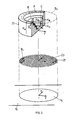
- an evaporation surface 14 to be evaporated for example on a crucible 15
- the x, y values of these beam positions to be controlled are stored in the position memory 1b and their number, 1 to n, can be output at an output A 1.
- the position clock generator 1a cyclically activates the position memory 1b via its output c1, so that the latter outputs at its output A1 the respective x, y values to be controlled, which are supplied to the position controller 3a of the electron gun 3.
- a switching unit T 1 is initially opened.
- the position signal x, y then output at the output A 1 is fed to a field assignment memory 5.
- each of the n intended beam positions x, y are assigned field identifications A, B ..., a plurality of positions x, y jointly belonging to the same field identifications.
- the field assignment memory 5 thus comprises significantly fewer field identifications A, B ... than beam positions can be controlled by the deflection control unit 1.
- the respective field identification is output at its output A 4.
- the field identification which is now output at the output A5 of the field assignment memory 5, is fed to a correction quantity memory 7, wherein for each field identification A, B ... one correction each value K A , K B ... is stored and which, according to the field identification at output A5, outputs the corresponding correction value K A , K B etc. at output A7.
- the correction quantity value K corresponding to this position is output, which corresponds to the field A or B ..., in which said position is located .
- the switching unit T 1 By outputting the correction quantity K at the output A7 of the correction quantity memory 7, the switching unit T 1 is closed via a pulse shaper 9, so that the position signal x, y still present at the output A 1 via a hold circuit 11, which is also triggered by the pulse shaper 9, the position control 3a of the electron gun 3 is supplied.
- the output correction value K is fed via a scaling unit 13 as a control variable signal to an operating parameter actuator unit 3b and there sets an operating parameter for the electron gun 3, such as the dwell time of the electron beam 12 at the point on the evaporation surface 14 that is now controlled according to the pending x, y value its focus at that point or its performance at that point.
- the electron beam 12 works from the point now controlled, while the switching unit T 1 as which is open and the setting for the next item to be processed is prepared by the procedure described above, first by selecting the next item number, then the new item, the new field identification and finally the new correction variable.
- the position clock generator 1 a as shown, cyclically switches on the position numbers 1 to n, so that the surface 14 to be evaporated is repeatedly processed.
- the correction variable values K can be set or preselected on the correction variable memory 7, preferably adjusted, namely by a previously stored “working point” in the correction variable memory 7.
- the dwell time of the beam 12 is preferably set as the operating parameter on the operating parameter actuator unit 3b.
- the electron gun used is e.g. an electron gun of a known type, such as an electron gun ESQ 200 from Balzers AG.
- item number 14 denotes the given evaporation surface to be processed, for example in the evaporation crucible 15.
- a position grid 21 for the electron beam 12 is assigned to the evaporation surface 14.
- This position grid is divided into a plurality of identical position increments 23, which the electron beam 12 can control.
- the position grid 23 merges into a continuous grid with increasing grid fineness, ie in this case the beam can be steered continuously into any position with respect to the surface 14.
- a correction variable K is assigned to each position of the beam 12 relative to the surface 14, corresponding to x, y, it being emphasized that a large number of Beam positions x, y are each assigned the same correction variable K, since a large number of positions belong to the same field A, B ... It can be seen, for example according to FIG. 2, that all beam positions which lie on an outer, peripheral ring field A are assigned the correction variable K A.
- the correction variable K B is assigned to all beam positions which lie on a subsequent concentric ring field B and finally the correction variable K C etc. is also assigned to further concentric ring fields.
- 1 is preferably adjustable, is more preferred the position / field assignment is specified.
- a first variant of a beam path is shown with respect to the surface 14 at B1. If such a path B 1 is controlled by the deflection control 1 according to FIG. 1, the electron beam 12 follows a path which processes the surface 14 in a meandering pattern. If this path B 1 is placed on the correction size grid 25, it can be seen that with such a grid 25 formed from concentric circular fields, the control size S 1 3 of FIG. 1 resulting from the respective correction sizes K is changed at most undesirably frequently. This can now be remedied when the correction size grid 25 is known in a simple manner in that not a meandering path B 1 is selected, but rather a path which processes the surface 14 from inside to outside or from outside to inside in circular paths.
- a starting position number specification unit 30 is entered at which beam position the path determination process is to begin.
- the position number appearing at the output A30 is fed via an OR logic unit 32 to a position memory 1c.
- the position memory 1c the x, y values of all points to be processed by the beam 12 on the evaporation surface 14 are stored and are off by entering the assigned position numbers at the input E1, at the output A1 giveable.
- a signal at the control input S 1 of the position memory 1 c deletes the memory content in accordance with the x, y value whose position number is present at the input E 1.
- the position memory 1c is actuated by a further control signal U for the cyclical, single output of all position values x, y remaining in it.
- the position value x, y corresponding to the start number now appears at the output A1 and is fed via an OR link unit 34 to the input E5 of the field assignment memory 5, whereupon the latter the field identification A, B ... corresponding to the position. outputs at output A5.
- the field identification is now fed from the output A5 to the input E7 of the correction variable memory 7, whereupon the latter outputs the correction variable K A or K B ... corresponding to the identified field at the output A7 in the manner described above.
- a changeover unit T2 is switched to the position shown in solid lines in FIG. 3, and the correction value appearing at the output A7 is an instantaneous value memory 42 entered.
- the bistable unit 40 reset, whereupon the switch unit T2 falls back into the position shown in dashed lines.
- the output pulse of the pulse shaper 44 is fed to the reset input S 1, whereby the memory content of the position memory 1 c is deleted, which is defined by the position number pending at the input E 1. Accordingly, when the correction value just stored in the instantaneous value memory 42 appears at the position memory 1c, the memory content corresponding to the starting position is deleted. This position value is not lost, however, because it was entered during the current storage of the associated correction variable, by closing a switching unit T3 and switching unit T4 switched in dashed position, an optimal path position memory 48. This was done by closing the switching unit T3 with the switching unit T2 to the memory 42 switching output signal of the bistable unit 40th
- the memory content corresponding to the start position number in the position memory 1c is thus deleted, but is stored in the optimum path position memory 48.
- the control input U is driven to the position memory 1c, whereupon the position memory 1c in a cycle all remaining x, y position values at its output A1 issues.
- the OR link unit 34 the field assignment memory 5 and the correction variable memory 7, a switchover unit T5 switched in the extended position, all correction variable values K corresponding to the positions remaining in the position memory 1c are thus cyclically fed to a difference unit 50, together with the correction variable value stored in the instantaneous value memory 42.
- the difference ⁇ of the correction quantities K of all positions remaining in the position memory 1c are fed to a difference storage unit 52, namely simultaneously with the respective position number m extracted from the position memory 1c, a correction quantity difference ⁇ K with the number of the position m, the one of which is stored in the memory 52 Correction quantity was related to the correction quantity stored in the memory 42.
- the following function is thus stored in the difference memory 52: correction value difference of all correction values which correspond to the positions remaining in the position memory 1 c to the correction value corresponding to the starting position as a function of the position number m.
- This function ⁇ K m which lies in the differential memory 52 after the position memory 1c has been circulated once, is fed to a minimum determination unit 54, which detects at which position number m min the difference ⁇ K m in the differential memory 52 is minimal.
- Position number m min is fed to the OR unit 32, then the input E1 of the position memory 1c. This newly found position number now has exactly the same effect as the start number of output A30 entered in advance to start the process:
- the assigned x, y position appears at the output of the position memory 1c, is fed via the OR combination unit 34 to the field assignment memory 5, the output of which is sent to the correction variable memory 7, the output of which is in turn only to the instantaneous value memory 42, where it is temporarily stored.
- the position value output at the output A 1 is further fed to the optimal path position memory 48 as the next position x2 ', y2', after which it is deleted in the position memory 1c by circulating the position memory 1c.
- the remaining position values again the correction quantity difference as a function of the position numbers remaining in the position memory 1c, are stored in the memory 52, after which the new minimum number m min is determined at the minimum determination unit 54, etc.
- the position sequence now stored in this memory 48 corresponds to a movement path for the beam 12 of the electron gun 3, in which si It is established that, progressing from position to position, minimal correction size steps have to be carried out.
- a counter 56 counts the number of times the instantaneous value memory 42 has been loaded and, as soon as its count corresponds to the number of beam positions n to be controlled, controls a bistable unit 58. This indicates that the optimal path mentioned is stored in the optimal path memory 48.
- the search process for this optimal path is now complete, and the positioning process for the beam 12 of the electron gun 3, which is now starting, is controlled starting from this optimal path memory 48, which now takes the place of the position memory 1c: the output signal of the bistable unit 58 opens the switching unit T4 for this purpose and closes a further switching unit T6 on the output side of the optimal path position memory 48, whereby its output A48 is switched to the OR logic unit 34.
- the output A48 is led to the position control input on the electron gun 3 by closing the switching unit T6. Also by the output signal A58 of the bistable unit 58, the switch unit T5 is placed in the position shown in dashed lines, whereby the output A7 of the correction quantity memory 7 is fed to the electron gun 3 via the scaling unit 9 of the operating parameter setting unit 3b.
- a clock 60 is triggered further by the output signal A58 of the bistable unit 48, whose output signal A60 is now in order, and thus the Corresponding to the optimal path, the position signals from the optimal path position memory 48 are clocked out, with which, on the one hand, the electron gun 12 follows this optimal path via the position controller 3a, and on the other hand, via the OR combination unit 34, the field assignment memory 5 and the correction variable memory 7, the selected operating parameters, such as the beam dwell time, its focus or power, is set on the operating parameter setting unit 3b.
- the position memory 1c is then not activated with the control signal U to circulate all the memory contents remaining in it, but rather only the positions numbered next in x and y are activated to form the difference.
- FIG. 4 shows a further embodiment variant of the system according to the invention, starting from its con Figure according to Fig. 1, shown, ie with a given beam path. As will be seen, it may be indicated with such a further development to expand the system with the arrangements searching for the optimal beam path, as were shown with reference to FIG. 3, this expansion taking place in analogy to the illustration in FIG. 3.
- the deflection control 1 operated like that shown in FIG. 1, outputs the respective position signal x, y at its output A 1 and clocked by the position clock 1a.
- a plurality of mutually associated sets of a field assignment memory and a correction variable memory 5a / 7a, 5b / 7b etc. are now provided. All of the n beam positions x, y to be controlled are assigned a field distribution in each of these sets, for example fields A a , B a ..., D a in set "a” and fields A b , B b in set "b". .., C b , which do not match in the general case.
- the corresponding correction variables K are added to these record-specific fields in the assigned correction quantity memories 7 a and 7 b .
- connection arrangements 70 are provided, by means of which on the one hand the output A 1 can be connected in analogy to the explanations of FIG. 1, but now selectively, one or more of the field allocation memories 5. Accordingly, the outputs A7 of one or more of the provided sets 5/7 are switched to a logic unit 72.
- all of the correction variables output at the respectively activated outputs A verknüpft are linked to one another, preferably weighted added or multiplied, so that a signal occurs at the output A72 of the linking unit 72, via the scaling unit 13, converted into the actuating signal S13, which is a function of Correction variable (s) of one or more of the applied field assignment / correction variable memory sets 5/7.
- a correction size grid preferably corresponding to the influence of a physical quantity on the effect of the electron beam 12 with respect to the surface 14 to be evaporated, is stored in analogy to the correction size grid 25 from FIG. 2.
- the fields and correction variables of an annulus field correction variable grid are stored in the field assignment / correction variable memory set "a".
- a correction size grid with this profile takes into account, on an axially symmetrical evaporation crucible, the thermal diffusion conditions to the cooled outer wall of the crucible circular isotherms can be represented.
- field and correction quantity relationships are stored, which define a correction quantity grid, as shown in FIG. 5a, which takes into account the influence of the changing focusing during the deflection of an electron beam, which undergoes a 270 ° deflection between the electron beam source and the evaporation surface 14, in a plane perpendicular to the evaporation surface, for example through the y-axis.
- a further field assignment / correction variable memory set defines, for example, a correction variable grid with the profile according to FIG. 5 b, which, with sickle-shaped fields, influences the lateral deflection in the x direction, for example the aforementioned electron beam gun. Takes into account, in which the beam is deflected only by 270 ° in a plane perpendicular to the evaporation plane 14 and through the drawn y-axis from the electron beam source.
- connection arrangement 70 determines which of the correction size grids are to be used in an intended evaporation process. It should be emphasized again that a beam position x, y in each set can belong to a different field and therefore retrieves a different correction quantity at each set, and that all correction quantities - one or more - finally form the actuating signal S13 are preferably linked multiplicatively or additively to one another at the linking unit 72.
- the control quantity signal S13 is shown when two field assignment / correction quantity memory sets 5/7 are used, with one set a correction quantity grid, as shown at 74, is defined, with the other set a correction quantity grid as shown at 76 . 4, as a multiplication unit, by which the correction variable values K assigned to the fields are multiplied with one another, there is a profile of the control variable signal S13 over the x, y plane, i.e. actually the evaporation surface 14, as shown at 78 in FIG. 6.
- the control variable signal pattern 80 and 82 shown in FIG. 7 results in a control variable signal curve over the evaporation surface 14, as shown at 84.
Landscapes
- Chemical & Material Sciences (AREA)
- Engineering & Computer Science (AREA)
- Organic Chemistry (AREA)
- Chemical Kinetics & Catalysis (AREA)
- Materials Engineering (AREA)
- Mechanical Engineering (AREA)
- Metallurgy (AREA)
- Analytical Chemistry (AREA)
- Toxicology (AREA)
- Health & Medical Sciences (AREA)
- Physics & Mathematics (AREA)
- Plasma & Fusion (AREA)
- Electron Beam Exposure (AREA)
- Physical Vapour Deposition (AREA)
Applications Claiming Priority (2)
| Application Number | Priority Date | Filing Date | Title |
|---|---|---|---|
| CH417288 | 1988-11-10 | ||
| CH4172/88 | 1988-11-10 |
Publications (2)
| Publication Number | Publication Date |
|---|---|
| EP0368037A1 true EP0368037A1 (fr) | 1990-05-16 |
| EP0368037B1 EP0368037B1 (fr) | 1994-07-06 |
Family
ID=4271145
Family Applications (1)
| Application Number | Title | Priority Date | Filing Date |
|---|---|---|---|
| EP89119229A Expired - Lifetime EP0368037B1 (fr) | 1988-11-10 | 1989-10-17 | Procédé de commande de la distribution du taux d'évaporation produite par un faisceau d'électrons |
Country Status (5)
| Country | Link |
|---|---|
| US (1) | US5003151A (fr) |
| EP (1) | EP0368037B1 (fr) |
| JP (1) | JP2878340B2 (fr) |
| AT (1) | ATE108283T1 (fr) |
| DE (1) | DE58908004D1 (fr) |
Cited By (1)
| Publication number | Priority date | Publication date | Assignee | Title |
|---|---|---|---|---|
| DE19745771A1 (de) * | 1997-10-16 | 1999-04-29 | Leybold Ag | Verfahren für den Betrieb eines Hochleistungs-Elektronenstrahls |
Families Citing this family (5)
| Publication number | Priority date | Publication date | Assignee | Title |
|---|---|---|---|---|
| US6215127B1 (en) * | 1999-03-08 | 2001-04-10 | Advanced Micro Devices, Inc. | Method of using critical dimension mapping to qualify a new integrated circuit fabrication tool set |
| EP1275750B1 (fr) * | 2001-07-11 | 2009-07-01 | Carl Zeiss Vision GmbH | Appareil pour la métallisation sous vide |
| DE102016122671A1 (de) * | 2016-11-24 | 2018-05-24 | VON ARDENNE Asset GmbH & Co. KG | Verfahren und Elektronenstrahlkanone |
| DE102018101821A1 (de) * | 2018-01-26 | 2019-08-01 | VON ARDENNE Asset GmbH & Co. KG | Verfahren, Elektronenstrahlkanone und Steuervorrichtung |
| DE102018103079A1 (de) * | 2018-02-12 | 2019-08-14 | VON ARDENNE Asset GmbH & Co. KG | Verfahren, Elektronenstrahlkanone und Steuervorrichtung |
Citations (3)
| Publication number | Priority date | Publication date | Assignee | Title |
|---|---|---|---|---|
| EP0104922A2 (fr) * | 1982-09-27 | 1984-04-04 | Fujitsu Limited | Système d'exposition par faisceau d'électrons |
| DE3428802A1 (de) * | 1984-08-04 | 1986-02-13 | Leybold-Heraeus GmbH, 5000 Köln | Verfahren und vorrichtung zur steuerung des fokussierungszustandes eines abgelenkten elektronenstrahls |
| EP0222219A2 (fr) * | 1985-11-02 | 1987-05-20 | Leybold Aktiengesellschaft | Dispositif de bombardement d'un milieu par un faisceau d'électrons |
Family Cites Families (3)
| Publication number | Priority date | Publication date | Assignee | Title |
|---|---|---|---|---|
| US3607222A (en) * | 1968-11-26 | 1971-09-21 | Air Reduction | Method for evaporating alloy |
| US3875416A (en) * | 1970-06-30 | 1975-04-01 | Texas Instruments Inc | Methods and apparatus for the production of semiconductor devices by electron-beam patterning and devices produced thereby |
| CA1288733C (fr) * | 1985-09-05 | 1991-09-10 | The Black Clawson Company | Dispositif tamiseur de pates papetieres de fibres |
-
1989
- 1989-10-17 AT AT89119229T patent/ATE108283T1/de not_active IP Right Cessation
- 1989-10-17 EP EP89119229A patent/EP0368037B1/fr not_active Expired - Lifetime
- 1989-10-17 DE DE58908004T patent/DE58908004D1/de not_active Expired - Fee Related
- 1989-11-08 US US07/433,609 patent/US5003151A/en not_active Expired - Lifetime
- 1989-11-10 JP JP1291377A patent/JP2878340B2/ja not_active Expired - Fee Related
Patent Citations (3)
| Publication number | Priority date | Publication date | Assignee | Title |
|---|---|---|---|---|
| EP0104922A2 (fr) * | 1982-09-27 | 1984-04-04 | Fujitsu Limited | Système d'exposition par faisceau d'électrons |
| DE3428802A1 (de) * | 1984-08-04 | 1986-02-13 | Leybold-Heraeus GmbH, 5000 Köln | Verfahren und vorrichtung zur steuerung des fokussierungszustandes eines abgelenkten elektronenstrahls |
| EP0222219A2 (fr) * | 1985-11-02 | 1987-05-20 | Leybold Aktiengesellschaft | Dispositif de bombardement d'un milieu par un faisceau d'électrons |
Cited By (5)
| Publication number | Priority date | Publication date | Assignee | Title |
|---|---|---|---|---|
| DE19745771A1 (de) * | 1997-10-16 | 1999-04-29 | Leybold Ag | Verfahren für den Betrieb eines Hochleistungs-Elektronenstrahls |
| EP0910110A3 (fr) * | 1997-10-16 | 2000-12-27 | Balzers und Leybold Deutschland Holding AG | Procédé de commande d'un faisceau d'électrons de grande puissance |
| US6214408B1 (en) | 1997-10-16 | 2001-04-10 | Balzers Und Leybold Deutschland Holding Ag | Method for the operation of an electron beam |
| US6436466B2 (en) | 1997-10-16 | 2002-08-20 | Unaxis Deutschland Holding Gmbh | Method for the operation of an electron beam |
| DE19745771B4 (de) * | 1997-10-16 | 2005-12-22 | Unaxis Deutschland Holding Gmbh | Verfahren für den Betrieb eines Hochleistungs-Elektronenstrahls |
Also Published As
| Publication number | Publication date |
|---|---|
| ATE108283T1 (de) | 1994-07-15 |
| JPH03160713A (ja) | 1991-07-10 |
| JP2878340B2 (ja) | 1999-04-05 |
| DE58908004D1 (de) | 1994-08-11 |
| US5003151A (en) | 1991-03-26 |
| EP0368037B1 (fr) | 1994-07-06 |
Similar Documents
| Publication | Publication Date | Title |
|---|---|---|
| DE69937554T2 (de) | Synchron gemultiplexte architektur für vakuumverfahren mit einem überschuss nahenull | |
| EP0552616B1 (fr) | Procédé et dispositif pour traiter des pièces d'oeuvre par rayonnement du laser émis d'un laser | |
| EP0885348B1 (fr) | Procede et dispositif de regulation rapide de la puissance d'une centrale | |
| DE1185305B (de) | Verfahren zum Loeten, Schweissen und Abtragen von Materialien mittels eines Ladungstraegerstrahls | |
| DE1053691B (de) | Verfahren und Einrichtung zur Materialbearbeitung mittels Ladungstraegerstrahl | |
| DE3444161C2 (fr) | ||
| EP0368037B1 (fr) | Procédé de commande de la distribution du taux d'évaporation produite par un faisceau d'électrons | |
| DE3809630C1 (fr) | ||
| DE3546130C2 (de) | Verfahren zur Steuerung der Bearbeitung in einer Elektroerosionsmaschine mit einer Drahtelektrode | |
| DE102007012370A1 (de) | Bedampfungseinrichtung und Bedampfungsverfahren zur Molekularstrahlbedampfung und Molekularstrahlepitaxie | |
| DE4111106A1 (de) | Mehrdruck-steueranlage | |
| DE102010042777B4 (de) | Laserschneidanordnung und Verfahren zum Schneiden | |
| DE102009049270B4 (de) | Dampfphasenlötanlage mit Förderanlage | |
| DE102008019903A1 (de) | Kühltunnel und Verfahren zum Betrieb eines solchen | |
| EP0335122B1 (fr) | Dispositif et procédé le commande et de contrôle d'un faisceau d'électrons pour le travail des métaux | |
| DE4344803C2 (de) | Wasserstoffabsorbierende Metalle verwendendes Wärmeübertragungs-System | |
| DE4438303A1 (de) | Verfahren und Vorrichtung zum Elektronenstrahlschweißen | |
| EP0417337B1 (fr) | Procédé de fonctionnement d'une machine-outil à commande numérique ou d'un robot | |
| DE10051508A1 (de) | Verfahren und Einrichtung zur Reduzierung Zündspannung von Leistungspulsen gepulst betriebener Plasmen | |
| DE102004041855B4 (de) | Vorrichtung und Verfahren zur kontinuierlichen thermischen Vakuumbeschichtung | |
| DE202007018545U1 (de) | Maschine zum Bearbeiten von Werkstücken zum maschinellen Bearbeiten von Werkstücken | |
| DE1615449C2 (de) | Vorrichtung zur thermischen Oberflächenbehandlung von metallischen Werkstücken mittels Elektronenstrahlen | |
| EP0222219A2 (fr) | Dispositif de bombardement d'un milieu par un faisceau d'électrons | |
| DE3246268C3 (de) | Verfahren zur Steuerung eines Bearbeitungsautomaten mit mehreren Werkzeugen | |
| WO2000016373A1 (fr) | Ensemble cible pour chambre d'evaporation par l'intermediaire d'un arc |
Legal Events
| Date | Code | Title | Description |
|---|---|---|---|
| PUAI | Public reference made under article 153(3) epc to a published international application that has entered the european phase |
Free format text: ORIGINAL CODE: 0009012 |
|
| AK | Designated contracting states |
Kind code of ref document: A1 Designated state(s): AT BE CH DE ES FR GB GR IT LI LU NL SE |
|
| 17P | Request for examination filed |
Effective date: 19900531 |
|
| 17Q | First examination report despatched |
Effective date: 19921019 |
|
| GRAA | (expected) grant |
Free format text: ORIGINAL CODE: 0009210 |
|
| AK | Designated contracting states |
Kind code of ref document: B1 Designated state(s): AT BE CH DE ES FR GB GR IT LI LU NL SE |
|
| PG25 | Lapsed in a contracting state [announced via postgrant information from national office to epo] |
Ref country code: GR Free format text: LAPSE BECAUSE OF FAILURE TO SUBMIT A TRANSLATION OF THE DESCRIPTION OR TO PAY THE FEE WITHIN THE PRESCRIBED TIME-LIMIT Effective date: 19940706 Ref country code: ES Free format text: THE PATENT HAS BEEN ANNULLED BY A DECISION OF A NATIONAL AUTHORITY Effective date: 19940706 |
|
| REF | Corresponds to: |
Ref document number: 108283 Country of ref document: AT Date of ref document: 19940715 Kind code of ref document: T |
|
| GBT | Gb: translation of ep patent filed (gb section 77(6)(a)/1977) |
Effective date: 19940704 |
|
| REF | Corresponds to: |
Ref document number: 58908004 Country of ref document: DE Date of ref document: 19940811 |
|
| ET | Fr: translation filed | ||
| ITF | It: translation for a ep patent filed | ||
| PG25 | Lapsed in a contracting state [announced via postgrant information from national office to epo] |
Ref country code: SE Effective date: 19941006 |
|
| PLBE | No opposition filed within time limit |
Free format text: ORIGINAL CODE: 0009261 |
|
| STAA | Information on the status of an ep patent application or granted ep patent |
Free format text: STATUS: NO OPPOSITION FILED WITHIN TIME LIMIT |
|
| 26N | No opposition filed | ||
| PGFP | Annual fee paid to national office [announced via postgrant information from national office to epo] |
Ref country code: LU Payment date: 20011009 Year of fee payment: 13 |
|
| REG | Reference to a national code |
Ref country code: GB Ref legal event code: IF02 |
|
| PGFP | Annual fee paid to national office [announced via postgrant information from national office to epo] |
Ref country code: AT Payment date: 20021011 Year of fee payment: 14 |
|
| PG25 | Lapsed in a contracting state [announced via postgrant information from national office to epo] |
Ref country code: LU Free format text: LAPSE BECAUSE OF NON-PAYMENT OF DUE FEES Effective date: 20021017 |
|
| PGFP | Annual fee paid to national office [announced via postgrant information from national office to epo] |
Ref country code: NL Payment date: 20021031 Year of fee payment: 14 |
|
| PGFP | Annual fee paid to national office [announced via postgrant information from national office to epo] |
Ref country code: BE Payment date: 20021219 Year of fee payment: 14 |
|
| PG25 | Lapsed in a contracting state [announced via postgrant information from national office to epo] |
Ref country code: AT Free format text: LAPSE BECAUSE OF NON-PAYMENT OF DUE FEES Effective date: 20031017 |
|
| PG25 | Lapsed in a contracting state [announced via postgrant information from national office to epo] |
Ref country code: BE Free format text: LAPSE BECAUSE OF NON-PAYMENT OF DUE FEES Effective date: 20031031 |
|
| BERE | Be: lapsed |
Owner name: *BALZERS A.G. Effective date: 20031031 |
|
| PG25 | Lapsed in a contracting state [announced via postgrant information from national office to epo] |
Ref country code: NL Free format text: LAPSE BECAUSE OF NON-PAYMENT OF DUE FEES Effective date: 20040501 |
|
| NLV4 | Nl: lapsed or anulled due to non-payment of the annual fee |
Effective date: 20040501 |
|
| PGFP | Annual fee paid to national office [announced via postgrant information from national office to epo] |
Ref country code: FR Payment date: 20041008 Year of fee payment: 16 |
|
| PGFP | Annual fee paid to national office [announced via postgrant information from national office to epo] |
Ref country code: GB Payment date: 20041013 Year of fee payment: 16 |
|
| PGFP | Annual fee paid to national office [announced via postgrant information from national office to epo] |
Ref country code: DE Payment date: 20041014 Year of fee payment: 16 |
|
| PGFP | Annual fee paid to national office [announced via postgrant information from national office to epo] |
Ref country code: CH Payment date: 20050124 Year of fee payment: 16 |
|
| PG25 | Lapsed in a contracting state [announced via postgrant information from national office to epo] |
Ref country code: IT Free format text: LAPSE BECAUSE OF NON-PAYMENT OF DUE FEES;WARNING: LAPSES OF ITALIAN PATENTS WITH EFFECTIVE DATE BEFORE 2007 MAY HAVE OCCURRED AT ANY TIME BEFORE 2007. THE CORRECT EFFECTIVE DATE MAY BE DIFFERENT FROM THE ONE RECORDED. Effective date: 20051017 Ref country code: GB Free format text: LAPSE BECAUSE OF NON-PAYMENT OF DUE FEES Effective date: 20051017 |
|
| PG25 | Lapsed in a contracting state [announced via postgrant information from national office to epo] |
Ref country code: LI Free format text: LAPSE BECAUSE OF NON-PAYMENT OF DUE FEES Effective date: 20051031 Ref country code: CH Free format text: LAPSE BECAUSE OF NON-PAYMENT OF DUE FEES Effective date: 20051031 |
|
| PG25 | Lapsed in a contracting state [announced via postgrant information from national office to epo] |
Ref country code: DE Free format text: LAPSE BECAUSE OF NON-PAYMENT OF DUE FEES Effective date: 20060503 |
|
| REG | Reference to a national code |
Ref country code: CH Ref legal event code: PL |
|
| GBPC | Gb: european patent ceased through non-payment of renewal fee |
Effective date: 20051017 |
|
| PG25 | Lapsed in a contracting state [announced via postgrant information from national office to epo] |
Ref country code: FR Free format text: LAPSE BECAUSE OF NON-PAYMENT OF DUE FEES Effective date: 20060630 |
|
| REG | Reference to a national code |
Ref country code: FR Ref legal event code: ST Effective date: 20060630 |