EP0368046B1 - Wagon transporteur sur rails - Google Patents
Wagon transporteur sur rails Download PDFInfo
- Publication number
- EP0368046B1 EP0368046B1 EP89119371A EP89119371A EP0368046B1 EP 0368046 B1 EP0368046 B1 EP 0368046B1 EP 89119371 A EP89119371 A EP 89119371A EP 89119371 A EP89119371 A EP 89119371A EP 0368046 B1 EP0368046 B1 EP 0368046B1
- Authority
- EP
- European Patent Office
- Prior art keywords
- bunker
- truck
- height
- bogies
- wagon
- Prior art date
- Legal status (The legal status is an assumption and is not a legal conclusion. Google has not performed a legal analysis and makes no representation as to the accuracy of the status listed.)
- Expired - Lifetime
Links
- 239000000872 buffer Substances 0.000 claims description 8
- 239000002828 fuel tank Substances 0.000 claims description 2
- 230000002787 reinforcement Effects 0.000 claims description 2
- 238000009434 installation Methods 0.000 claims 1
- 239000000463 material Substances 0.000 description 42
- 230000002349 favourable effect Effects 0.000 description 4
- 238000009825 accumulation Methods 0.000 description 2
- 230000007423 decrease Effects 0.000 description 2
- 238000000034 method Methods 0.000 description 2
- 230000003014 reinforcing effect Effects 0.000 description 2
- 230000000717 retained effect Effects 0.000 description 2
- 229910000831 Steel Inorganic materials 0.000 description 1
- 238000010276 construction Methods 0.000 description 1
- 238000005065 mining Methods 0.000 description 1
- 230000000284 resting effect Effects 0.000 description 1
- 239000010959 steel Substances 0.000 description 1
Images

Classifications
-
- B—PERFORMING OPERATIONS; TRANSPORTING
- B61—RAILWAYS
- B61D—BODY DETAILS OR KINDS OF RAILWAY VEHICLES
- B61D11/00—Mine cars
-
- B—PERFORMING OPERATIONS; TRANSPORTING
- B61—RAILWAYS
- B61D—BODY DETAILS OR KINDS OF RAILWAY VEHICLES
- B61D3/00—Wagons or vans
- B61D3/16—Wagons or vans adapted for carrying special loads
-
- B—PERFORMING OPERATIONS; TRANSPORTING
- B61—RAILWAYS
- B61D—BODY DETAILS OR KINDS OF RAILWAY VEHICLES
- B61D47/00—Loading or unloading devices combined with vehicles, e.g. loading platforms, doors convertible into loading and unloading ramps
-
- E—FIXED CONSTRUCTIONS
- E01—CONSTRUCTION OF ROADS, RAILWAYS, OR BRIDGES
- E01B—PERMANENT WAY; PERMANENT-WAY TOOLS; MACHINES FOR MAKING RAILWAYS OF ALL KINDS
- E01B27/00—Placing, renewing, working, cleaning, or taking-up the ballast, with or without concurrent work on the track; Devices therefor; Packing sleepers
- E01B27/02—Placing the ballast; Making ballastway; Redistributing ballasting material; Machines or devices therefor; Levelling means
-
- E—FIXED CONSTRUCTIONS
- E01—CONSTRUCTION OF ROADS, RAILWAYS, OR BRIDGES
- E01B—PERMANENT WAY; PERMANENT-WAY TOOLS; MACHINES FOR MAKING RAILWAYS OF ALL KINDS
- E01B2203/00—Devices for working the railway-superstructure
- E01B2203/03—Displacing or storing ballast
- E01B2203/032—Displacing or storing ballast with special use or configuration of conveyor belts
-
- E—FIXED CONSTRUCTIONS
- E01—CONSTRUCTION OF ROADS, RAILWAYS, OR BRIDGES
- E01B—PERMANENT WAY; PERMANENT-WAY TOOLS; MACHINES FOR MAKING RAILWAYS OF ALL KINDS
- E01B2203/00—Devices for working the railway-superstructure
- E01B2203/03—Displacing or storing ballast
- E01B2203/034—Displacing or storing ballast using storing containers
- E01B2203/038—Displacing or storing ballast using storing containers detachable from the vehicle
Definitions
- the invention relates to a rail-bound transport wagon with a bunker that is laterally delimited by side walls and with a conveyor device that runs continuously in the area of the bunker floor, conveys upward from the loading end in the longitudinal direction of the wagon and projects over the buffers at the discharge end, with the clear wall height of the side walls of the bunker above the total wagon length is essentially the same.
- the transfer height to the following wagon essentially corresponds to the thickness of the projecting conveyor belt part and is significantly less than the clear height of the side walls of the bunker (side wall height above the conveyor belt top), which limits the height of the material column being conveyed upwards.
- a disadvantage of the Hägglund wagons is that the height of the material column is continuously increased when conveying over a larger number of transport wagons connected in series decreases (deliquescence). This means that the bunker capacity given by the bunker width and length and the clear height of the side walls is no longer fully utilized in the wagons at the rear of the conveyor chain, and additional wagons are required (coarser train length) to accommodate a certain amount of material.
- the object of the invention is to provide a cost-effective transport wagon that can be used on railway lines and has a favorable payload / dead load ratio, the bunker capacity of which is well utilized even when conveying via several similar transport wagons.
- the height difference of the conveyor between the loading end and the discharge end is substantially equal to the inside wall height of the side walls of the bunker or coarser than this wall height, and in that the frame connecting the two bogies is in its middle, essentially between the two bogies lying area is raised and runs there in the area of the sloping bunker.
- the frame of the transport wagon raised between the two bogies, supports the bunker in this area.
- the bunker can be designed with a comparatively low empty weight in such a way that a large volume of material can be taken up, which results in a favorable payload / dead load ratio.
- the material transfer height is in such a transport wagon in a subsequent wagon of the same type, coarser or equal to the maximum material height, which is limited over the entire length of the wagon by an essentially the same clear height of the side walls.
- the transport wagon at its discharge end always transfers the material essentially from above onto the material at the loading end of the next wagon, which means that the height of the material column being conveyed, which extends to the full clear height of the side walls of the bunker, is essentially retained even over many transport wagons connected in series.
- the rough bunker capacity of the individual transport wagons which is roughly the same over the entire length of the wagon, is fully utilized and the train length can be kept shorter.
- the design of the transport wagon according to the invention allows a further mode of operation in which the material is resting on the conveyor at a low height Material is conveyed over (several) transport wagons and then stored in a specific transport wagon using the full bunker contents.
- the conveyor of the storage transport wagon is operated in the so-called stop-and-go process, ie one waits until a material accumulation has formed on the conveyor at the loading end of the storage transport wagon, the height of which corresponds approximately to the clear height of the side wall of the bunker , and then moves a little further with the conveyor. Due to the design of the transport wagon in accordance with the innovation, one single conveyor device (per transport wagon), ie without a separate transfer belt for material transfer to the following wagon, is sufficient.
- the large transfer height achieved by the relatively large height difference of the conveyor between the loader and the discharger allows material to be stored in the storing transport wagon up to the full clear height of the side walls (through supervised stop-and-go operation of the storing conveyor belt even when material is fed unevenly) of the bunker, i.e. using the full bunker capacity.
- the transport wagons are successively filled with material that is being conveyed from previous transport wagons at a low height. After some transport wagons have been filled, they can be uncoupled from the rest of the train and driven away. The material is now stored in the remaining transport wagons.
- the accumulated part is saved, advantageously up to the full clear height of the bunker side walls Transfer the material column in the remaining transport wagons into these empty transport wagons, whereby due to the new design of the transport wagons, a decrease in the material height and a related poor utilization of the bunker contents can be largely avoided even if the material column is passed on over several transport wagons.
- Suitable conveyor devices are, in particular, endlessly rotating conveyor belt units which are deflected via deflection devices at the loading end and discharge end, the upper run of the conveyor belt unit running obliquely upwards in one plane from the loading end to the discharge end.
- the frame in the middle area of the transport wagon is formed only from the bunker stiffened in the middle area mentioned.
- the buffer forces can be safely absorbed without providing a separate frame that connects the two bogies below the sloping bunker.
- the force introduction from the frame part carrying the buffers, on which the respective bogie is also mounted, in the middle bunker stiffened with reinforcing elements is advantageously carried out by means of struts which run obliquely upwards.
- FIG. 1 shows a side view of a transport wagon according to the invention
- FIG. 2 shows a top view of the transport wagon shown in FIG. 1
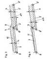
- FIG. 3 shows schematically the transfer of a material column from a transport wagon to the following wagon
- FIG. 4 shows schematically the storage operation in which material is stored at a low height and / or discontinuously in the following wagon using the full bunker capacity.
- the transport wagon shown in FIGS. 1 and 2 has a bunker delimited by side walls 1 with areas 1a chamfered at the top, in the bottom area of which a belt conveyor device 3 is arranged, which runs obliquely upwards in the longitudinal direction of the wagon from the loading end 4 and at the discharge end 5 the buffers 6 protrude in order to enable material to be transferred to the following wagon 7, which is only partially shown.
- the belt conveyor device shown schematically in FIGS. 1 and 2 essentially consists of an endlessly rotating belt conveyor unit which is deflected around the deflection drums 8 and 9 and is driven by the deflection drum (drive drum) 9 arranged at the discharge end.
- the height difference ⁇ H of the conveyor 3, 8 and 9 between the loading end 4 and the discharge end 5 is substantially equal to the inside wall height h of the side walls 1 of the bunker or greater than this wall height h.
- the clear wall height of the side walls 1 of the bunker is the same over the entire length of the bunker in the exemplary embodiment shown and is shown in FIG. 1.
- the height difference of the conveyor 3, 8, 9 between loading end 4 and discharge end 5 can be seen in FIG. 3.
- the design of the transport wagons according to the invention allows a further operating mode shown in FIG. 4, in which material 11 lying at a low height and / or only partially on the conveying device 3 is first conveyed via (several) transport wagons and then in a specific transport wagon (the Follow car 7) is saved using the full bunker content.
- the conveyor 3 'of the storing transport wagon 7 in the so-called stop-and-go method, ie one waits until a material accumulation has formed on the conveyor 3', the height of which corresponds approximately to the clear height h of the side wall 1 of the bunker and then moves a bit further with the conveyor 3 '.
- the design of the transport wagon can be done with a single, continuous conveyor (per transport wagon), that is, without a separate transfer belt for material transfer to the following wagon 7.
- the large transfer height achieved by the relatively large height difference .DELTA.H of the conveying device 3 between the loading end 4 and the discharge end 5 allows material to be stored in the storage transport wagon 7 up to the full clear height h of the side walls of the bunker, that is to say using the full bunker capacity.
- a supervised stop-and-go operation of the storage conveyor belt 3 ' can be achieved even with unevenly fed via the conveyor belt 3, a relatively uniform material storage up to the full clear height of the storage bunker.
- the frame 23 is in the central region of the bogies 15 and 16, which is essentially between the two bogies Transport wagons pulled up and running there in the area of the obliquely upward bunker, which is reinforced in this area by reinforcing elements 17 running obliquely upward in order to be able to absorb the forces that arise.
- the force is introduced from the frame parts 18 and 19, which support the buffers 6 and on which the bogies 15 and 16 are mounted, into the stiffened bunker in the central region essentially via oblique struts 20 and 21.
- the bunker has spaced-apart stanchions distributed over the length of the bunker in the central region, which are connected to the side walls 1 and, as can be seen from FIG. 2, are closed at the top. These stanchions can be pulled further down in the end regions of the bunker below the bunker floor and connected to the frame parts 18 and 19, respectively.
- the transport wagon shown in FIGS. 1 and 2 is characterized by a simple, weight-saving structure which, together with the large bunker content, enables a favorable payload / dead load ratio.
- the space underneath the frame area 23 drawn up between the bogies can advantageously be used to accommodate in particular a diesel engine, a hydraulic device, a fuel tank, a brake system and / or an operating cabin (not shown in more detail).
- belt conveyor other continuous conveyors such as scraper chain conveyors, steel link belts or vibrating troughs etc. are used.
- Continuous is also understood to mean those conveying devices in which the actual conveying means consists of individual, interconnected and jointly driven elements. It is essential, however, that the transport wagon according to the invention manages without a separate transfer belt for the material transfer to the next wagon and is therefore structurally simple, and can use the full wagon length for material storage in the full clear height of the side walls.
Landscapes
- Engineering & Computer Science (AREA)
- Transportation (AREA)
- Mechanical Engineering (AREA)
- Architecture (AREA)
- Civil Engineering (AREA)
- Structural Engineering (AREA)
- Filling Or Emptying Of Bunkers, Hoppers, And Tanks (AREA)
- Intermediate Stations On Conveyors (AREA)
Claims (8)
- Wagon transporteur sur rails avec une soute limitée latéralement par des parois latérales et avec un convoyeur s'étendant continûment au niveau du sol de la soute, fonctionnant incliné vers le haut depuis l'extrémité de chargement, selon la direction longitudinale du wagon, et faisant saillie à l'extrémité de déchargement au-dessus des tampons, dans lequel la hauteur de paroi des parois latérales de la soute est sensiblement constante sur toute la longueur du wagon,
caractérisé en ce que la différence de hauteur (ΔH) du convoyeur (3, 8, 9) entre l'extrémité de chargement (4) et l'extrémité de déchargement (5) est essentiellement identique ou supérieure à la hauteur intérieure de paroi (h) des parois latérales (1) de la soute, et en ce que le châssis (23) reliant les deux bogies (15, 16) est réhaussé dans sa partie médiane située sensiblement entre les deux bogies (15, 16) et s'intègre à cet endroit au niveau de la soute s'étendant de façon inclinée vers le haut. - Wagon transporteur selon la revendication 1,
caractérisé en ce que le convoyeur présente une bande de convoyage (3) circulant sans fin, qui s'enroule autour de dispositifs de renvoi (8, 9) à l'extrémité de chargement (4) et de déchargement (5) respectivement. - Wagon transporteur selon la revendication 2,
caractérisé en ce que le brin supérieur de la bande transporteuse (3) circule dans un plan incliné vers le haut depuis l'extrémité de chargement (4) vers l'extrémité de déchargement (5). - Wagon transporteur selon l'une des revendications précédentes,
caractérisé en ce que le châssis (23) est constitué dans la zone médiane du wagon transporteur seulement par ladite soute rigidifiée dans ladite zone médiane. - Wagon transporteur selon l'une des revendications précédentes,
caractérisé en ce que la soute présente des éléments de renforcement (17) s'étendant de façon inclinée vers le haut ou selon la direction de la soute, disposés au moins dans la zone médiane du wagon transporteur au niveau du sol de la soute. - Wagon transporteur selon l'une des revendications précédentes,
caractérisé en ce que la portion de châssis (19) portant les tampons (6), sur laquelle est monté le bogie (16) eut reliée à la soute essentiellement par l'intermédiaire d'au moins une entretoise (21) s'étendant de façon inclinée vers le haut. - Wagon transporteur selon l'une des revendications précédentes,
caractérisé en ce que la portion de châssis (18) portant les tampons (6), sur laquelle est monté le bogie (15) est reliée à la soute essentiellement par l'intermédiaire d'au moins une entretoise (20) s'étendant de façon inclinée vers le haut. - Wagon transporteur selon l'une des revendications précédentes,
caractérisé en ce que, sous la portion de châssis réhaussée entre les bogies, est (sont) disposé(s) un moteur diesel, un dispositif hydraulique, un réservoir de carburant, une installation de freinage et/ou une cabine de commande.
Priority Applications (1)
| Application Number | Priority Date | Filing Date | Title |
|---|---|---|---|
| AT89119371T ATE87047T1 (de) | 1988-11-05 | 1989-10-19 | Schienengebundener transportwaggon. |
Applications Claiming Priority (4)
| Application Number | Priority Date | Filing Date | Title |
|---|---|---|---|
| DE8813858U DE8813858U1 (de) | 1988-11-05 | 1988-11-05 | Schienengebundener Transportwaggon |
| DE8813858U | 1988-11-05 | ||
| DE8908700U DE8908700U1 (de) | 1988-11-05 | 1989-07-18 | Schienengebundener Transportwaggon |
| DE8908700U | 1989-07-18 |
Publications (3)
| Publication Number | Publication Date |
|---|---|
| EP0368046A2 EP0368046A2 (fr) | 1990-05-16 |
| EP0368046A3 EP0368046A3 (fr) | 1991-04-03 |
| EP0368046B1 true EP0368046B1 (fr) | 1993-03-17 |
Family
ID=25953738
Family Applications (1)
| Application Number | Title | Priority Date | Filing Date |
|---|---|---|---|
| EP89119371A Expired - Lifetime EP0368046B1 (fr) | 1988-11-05 | 1989-10-19 | Wagon transporteur sur rails |
Country Status (2)
| Country | Link |
|---|---|
| EP (1) | EP0368046B1 (fr) |
| DE (2) | DE8908700U1 (fr) |
Families Citing this family (7)
| Publication number | Priority date | Publication date | Assignee | Title |
|---|---|---|---|---|
| AU643872B2 (en) * | 1991-02-27 | 1993-11-25 | Franz Plasser Bahnbaumaschinen-Industriegesellschaft M.B.H. | A transport wagon |
| US5277538A (en) * | 1991-03-26 | 1994-01-11 | Franz Plasser Bahnbaumaschinen-Industriegesellschaft M.B.H. | Loading car for bulk material |
| AT398993B (de) * | 1992-03-16 | 1995-02-27 | Plasser Bahnbaumasch Franz | Transportwagen mit einem auf schienenfahrwerken abgestützten wagenrahmen |
| AT5703U3 (de) * | 2002-07-23 | 2003-09-25 | Plasser Bahnbaumasch Franz | Speicherwagen mit einer tasteinrichtung |
| US9868451B2 (en) | 2013-03-15 | 2018-01-16 | Georgetown Rail Equipment Company | Self-unloading aggregate train |
| MX354836B (es) | 2014-11-05 | 2018-03-21 | Herzog Railroad Services Inc | Formación de carros de transporte y distribución de material con vagones tolva con compuertas y sistemas transportadores. |
| AT520268B1 (de) * | 2017-08-11 | 2020-01-15 | Plasser & Theurer Export Von Bahnbaumaschinen Gmbh | Speicherwagen für Schüttgut |
Family Cites Families (2)
| Publication number | Priority date | Publication date | Assignee | Title |
|---|---|---|---|---|
| DE3219025C2 (de) * | 1982-05-19 | 1984-09-20 | Max Knape GmbH & Co Bauunternehmung, 8011 Kirchheim | Transportzug für Gleisbehandlungszwecke und Verfahren zu dessen Befüllung und Entleerung |
| AT389333B (de) * | 1986-09-08 | 1989-11-27 | Plasser Bahnbaumasch Franz | Gleisverfahrbare schuettgutverladewagen-anordnung mit regelbaren entladeschurren |
-
1989
- 1989-07-18 DE DE8908700U patent/DE8908700U1/de not_active Expired
- 1989-10-19 DE DE8989119371T patent/DE58903804D1/de not_active Expired - Fee Related
- 1989-10-19 EP EP89119371A patent/EP0368046B1/fr not_active Expired - Lifetime
Also Published As
| Publication number | Publication date |
|---|---|
| EP0368046A3 (fr) | 1991-04-03 |
| DE58903804D1 (de) | 1993-04-22 |
| EP0368046A2 (fr) | 1990-05-16 |
| DE8908700U1 (de) | 1989-09-07 |
Similar Documents
| Publication | Publication Date | Title |
|---|---|---|
| EP0599799B1 (fr) | Wagon chargeur pour transporter des produits en vrac | |
| DD210321A5 (de) | Schuettgutverladewagen, insbesondere zur abraumverladung von einer schotterbett-reinigungsmaschine | |
| DD261618A5 (de) | Gleisverfahrbarer schuettgutverladewagen | |
| DE3886278T2 (de) | Müllfahrzeug mit seitlich angebrachter Ladevorrichtung. | |
| CH615969A5 (en) | Movable machine arrangement for transporting bulk material | |
| EP0368046B1 (fr) | Wagon transporteur sur rails | |
| DE3219025C2 (de) | Transportzug für Gleisbehandlungszwecke und Verfahren zu dessen Befüllung und Entleerung | |
| EP0878369A1 (fr) | Wagon de manutention de materiau en vrac | |
| AT400836B (de) | Schüttgutverladewagen | |
| EP4032777B1 (fr) | Dispositif porteur et wagon poche | |
| DE3123791A1 (de) | Verfahren und vorrichtung zur handhabung und transport - insbesondere zwischen einem ro-ro-schiff und einem terminal - einer einheitslast, die aus einem oder mehreren containern oder dergleichen besteht | |
| DE4213925C2 (de) | Wagenzug zum Speichern und für den Transport von Schüttgut | |
| DE202020102392U1 (de) | Schienengebundener Plattformwagen mit Förderband und Ladefläche | |
| DE2146590A1 (de) | Trichterwagen mit Vorrichtungen zum automatischen Beladen und Entladen | |
| EP0360235A2 (fr) | Camion à superstructure en forme de boîte comprenant une paroi avant mobile | |
| DE8813858U1 (de) | Schienengebundener Transportwaggon | |
| EP0677424B1 (fr) | Véhicule de transport de matériaux en plaque | |
| DD249298A1 (de) | Aus schienengebundenen schuettguttransportwagen bestehender transportzug | |
| DE69300556T2 (de) | Selbstbe- und entladener hochbordiger güterwagen. | |
| DE3206924C2 (fr) | ||
| EP0587063B1 (fr) | Véhicule utilitaire avec conteneurs pour matériaux en vrac | |
| DE2450455A1 (de) | Lastkraftwagen mit einer mulde fuer schuettbares und/oder stueckiges ladegut | |
| DE1197808B (de) | Zugentleerungsanlage fuer Schuettgueter | |
| DE3313512A1 (de) | Verfahren und vorrichtung zur bergeentsorgung von bergwerken, insbesondere von steinkohlenaufbereitungen | |
| EP0744493A1 (fr) | Disposition de wagons sur rail |
Legal Events
| Date | Code | Title | Description |
|---|---|---|---|
| PUAI | Public reference made under article 153(3) epc to a published international application that has entered the european phase |
Free format text: ORIGINAL CODE: 0009012 |
|
| AK | Designated contracting states |
Kind code of ref document: A2 Designated state(s): AT CH DE FR GB IT LI |
|
| PUAL | Search report despatched |
Free format text: ORIGINAL CODE: 0009013 |
|
| AK | Designated contracting states |
Kind code of ref document: A3 Designated state(s): AT CH DE FR GB IT LI |
|
| 17P | Request for examination filed |
Effective date: 19910613 |
|
| 17Q | First examination report despatched |
Effective date: 19920219 |
|
| GRAA | (expected) grant |
Free format text: ORIGINAL CODE: 0009210 |
|
| AK | Designated contracting states |
Kind code of ref document: B1 Designated state(s): AT CH DE FR GB IT LI |
|
| REF | Corresponds to: |
Ref document number: 87047 Country of ref document: AT Date of ref document: 19930415 Kind code of ref document: T |
|
| ITF | It: translation for a ep patent filed | ||
| REF | Corresponds to: |
Ref document number: 58903804 Country of ref document: DE Date of ref document: 19930422 |
|
| GBT | Gb: translation of ep patent filed (gb section 77(6)(a)/1977) |
Effective date: 19930406 |
|
| EN | Fr: translation not filed | ||
| ET | Fr: translation filed | ||
| PLBE | No opposition filed within time limit |
Free format text: ORIGINAL CODE: 0009261 |
|
| STAA | Information on the status of an ep patent application or granted ep patent |
Free format text: STATUS: NO OPPOSITION FILED WITHIN TIME LIMIT |
|
| REG | Reference to a national code |
Ref country code: FR Ref legal event code: R1 |
|
| REG | Reference to a national code |
Ref country code: FR Ref legal event code: DS |
|
| 26N | No opposition filed | ||
| REG | Reference to a national code |
Ref country code: CH Ref legal event code: PUE Owner name: FRANZ PLASSER BAHNBAUMASCHINEN- INDUSTRIEGESELLSCH |
|
| REG | Reference to a national code |
Ref country code: GB Ref legal event code: 732E |
|
| REG | Reference to a national code |
Ref country code: FR Ref legal event code: TP |
|
| REG | Reference to a national code |
Ref country code: GB Ref legal event code: IF02 |
|
| PGFP | Annual fee paid to national office [announced via postgrant information from national office to epo] |
Ref country code: GB Payment date: 20060830 Year of fee payment: 18 |
|
| PGFP | Annual fee paid to national office [announced via postgrant information from national office to epo] |
Ref country code: AT Payment date: 20060912 Year of fee payment: 18 |
|
| PGFP | Annual fee paid to national office [announced via postgrant information from national office to epo] |
Ref country code: FR Payment date: 20060926 Year of fee payment: 18 Ref country code: CH Payment date: 20060926 Year of fee payment: 18 |
|
| PGFP | Annual fee paid to national office [announced via postgrant information from national office to epo] |
Ref country code: IT Payment date: 20061031 Year of fee payment: 18 |
|
| PGFP | Annual fee paid to national office [announced via postgrant information from national office to epo] |
Ref country code: DE Payment date: 20061129 Year of fee payment: 18 |
|
| GBPC | Gb: european patent ceased through non-payment of renewal fee |
Effective date: 20071019 |
|
| REG | Reference to a national code |
Ref country code: CH Ref legal event code: PL |
|
| PG25 | Lapsed in a contracting state [announced via postgrant information from national office to epo] |
Ref country code: DE Free format text: LAPSE BECAUSE OF NON-PAYMENT OF DUE FEES Effective date: 20080501 Ref country code: LI Free format text: LAPSE BECAUSE OF NON-PAYMENT OF DUE FEES Effective date: 20071031 Ref country code: CH Free format text: LAPSE BECAUSE OF NON-PAYMENT OF DUE FEES Effective date: 20071031 |
|
| PG25 | Lapsed in a contracting state [announced via postgrant information from national office to epo] |
Ref country code: AT Free format text: LAPSE BECAUSE OF NON-PAYMENT OF DUE FEES Effective date: 20071019 |
|
| REG | Reference to a national code |
Ref country code: FR Ref legal event code: ST Effective date: 20080630 |
|
| PG25 | Lapsed in a contracting state [announced via postgrant information from national office to epo] |
Ref country code: GB Free format text: LAPSE BECAUSE OF NON-PAYMENT OF DUE FEES Effective date: 20071019 |
|
| PG25 | Lapsed in a contracting state [announced via postgrant information from national office to epo] |
Ref country code: FR Free format text: LAPSE BECAUSE OF NON-PAYMENT OF DUE FEES Effective date: 20071031 |
|
| PG25 | Lapsed in a contracting state [announced via postgrant information from national office to epo] |
Ref country code: IT Free format text: LAPSE BECAUSE OF NON-PAYMENT OF DUE FEES Effective date: 20071019 |