EP0368360B1 - Dispositif pour fixer la mentonnière d'un casque - Google Patents
Dispositif pour fixer la mentonnière d'un casque Download PDFInfo
- Publication number
- EP0368360B1 EP0368360B1 EP19890120948 EP89120948A EP0368360B1 EP 0368360 B1 EP0368360 B1 EP 0368360B1 EP 19890120948 EP19890120948 EP 19890120948 EP 89120948 A EP89120948 A EP 89120948A EP 0368360 B1 EP0368360 B1 EP 0368360B1
- Authority
- EP
- European Patent Office
- Prior art keywords
- pair
- securing device
- plug
- resilient members
- projection
- Prior art date
- Legal status (The legal status is an assumption and is not a legal conclusion. Google has not performed a legal analysis and makes no representation as to the accuracy of the status listed.)
- Expired - Lifetime
Links
Images






Classifications
-
- F—MECHANICAL ENGINEERING; LIGHTING; HEATING; WEAPONS; BLASTING
- F16—ENGINEERING ELEMENTS AND UNITS; GENERAL MEASURES FOR PRODUCING AND MAINTAINING EFFECTIVE FUNCTIONING OF MACHINES OR INSTALLATIONS; THERMAL INSULATION IN GENERAL
- F16B—DEVICES FOR FASTENING OR SECURING CONSTRUCTIONAL ELEMENTS OR MACHINE PARTS TOGETHER, e.g. NAILS, BOLTS, CIRCLIPS, CLAMPS, CLIPS OR WEDGES; JOINTS OR JOINTING
- F16B21/00—Means for preventing relative axial movement of a pin, spigot, shaft or the like and a member surrounding it; Stud-and-socket releasable fastenings
- F16B21/06—Releasable fastening devices with snap-action
- F16B21/07—Releasable fastening devices with snap-action in which the socket has a resilient part
- F16B21/073—Releasable fastening devices with snap-action in which the socket has a resilient part the socket having a resilient part on its inside
-
- A—HUMAN NECESSITIES
- A42—HEADWEAR
- A42B—HATS; HEAD COVERINGS
- A42B3/00—Helmets; Helmet covers ; Other protective head coverings
- A42B3/32—Collapsible helmets; Helmets made of separable parts ; Helmets with movable parts, e.g. adjustable
- A42B3/326—Helmets with movable or separable chin or jaw guard
-
- A—HUMAN NECESSITIES
- A44—HABERDASHERY; JEWELLERY
- A44B—BUTTONS, PINS, BUCKLES, SLIDE FASTENERS, OR THE LIKE
- A44B11/00—Buckles; Similar fasteners for interconnecting straps or the like, e.g. for safety belts
- A44B11/25—Buckles; Similar fasteners for interconnecting straps or the like, e.g. for safety belts with two or more separable parts
- A44B11/26—Buckles; Similar fasteners for interconnecting straps or the like, e.g. for safety belts with two or more separable parts with push-button fastenings
- A44B11/263—Buckles; Similar fasteners for interconnecting straps or the like, e.g. for safety belts with two or more separable parts with push-button fastenings with a push-button acting perpendicularly to the main plane of the buckle
-
- E—FIXED CONSTRUCTIONS
- E05—LOCKS; KEYS; WINDOW OR DOOR FITTINGS; SAFES
- E05B—LOCKS; ACCESSORIES THEREFOR; HANDCUFFS
- E05B63/00—Locks or fastenings with special structural characteristics
- E05B63/24—Arrangements in which the fastening members which engage one another are mounted respectively on the wing and the frame and are both movable, e.g. for release by moving either of them
- E05B63/248—Arrangements in which the fastening members which engage one another are mounted respectively on the wing and the frame and are both movable, e.g. for release by moving either of them the striker being movable for latching, and pushed back by a member on the wing for unlatching, or vice versa
Definitions
- the present invention relates to a securing device particularly for use on motor cycle helmets which enable a mouth guard or a wind shield to be closed and opened by a single step of operation.
- the disclosed securing device includes a hook member adapted to secure a mouth guard or a wind shield to a helmet body.
- the mouth guard is often disengaged from the helmet body with the hook undone as the helmet is severely swung horizontally or longitudinally while the helmeted rider is running his motor cycle. This is literally ha zardous to safe riding.
- a securing device for a mouth guard or a wind shield of a helmet comprising a plug mounted on the helmet and a socket mounted on the mouth guard or the wind shield, characterized in that said plug has a plug holder including a pair of resilient members each extending inwardly transversely of said plug holder and a plug body detachably retained between said pair of resilient members, said plug body including a head at the front end thereof, and that said socket includes a socket body having a retaining recess for receiving said head and a presser detachably retained in said recess of the socket body, said presser including a pair of resilient members extending transversely therefrom and a push bar adapted to release said head from said retaining recess against tension of said pair of resilient members.
- the plug can be secured to the helmet body while the socket is secured to either the mouth guard or wind shield.
- the head of the plug is pushed laterally into the retaining recess from a space defined by a lateral member of the presser so as to be releasably engaged with the recess.
- the head of the plug is retracted to the plug holder by pushing the head with the presser.
- Figure 1 shows a helmet for a motor cycle comprising a helmet body A, a mouth guard B, a transparent wind shield C integrally formed therewith, and a pin D having a ratchet construction by which the mouth guard and the wind shield are pivotably rotatable and retained at desired position.
- a securing means 30 according to the present invention may be mounted on either the mouth guard B or the wind shield C.
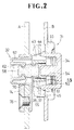
- the securing device 30 formed of a synthetic resin comprises a socket 31 mounted on either the mouth guard B or the wind shield C and a plug 32 mounted on the helmet body A, the socket 31 being releasably received in the helmet body A as shown in Figure 2.
- the socket 31 is built up with a socket body 33 and a presser 34.
- the presser 34 comprises a base plate 53, a pair of resilient members 50, 50 each extending horizontally and integrally formed at each end thereof, a push bar 54 centrally extending integrally from the plate 53 and guide bars 55 and 56 extending transversely therefrom.
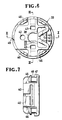
- the socket body 33 having an opening 35 for receiving the presser 34 and a retaining recess 37 communicating therewith ( Figures 8 and 9).
- the circular but partially opened recess 37 includes an inwardly directed protrusion 38 at an end portion thereof ( Figure 5).
- a pair of resilient guide members 40, 40 are located close to the opening 39 with each directed inwardly so as to guide the plug 32 into the retaining recess 37.
- the socket body 33 has an internal structure which includes a pair of guiding recesses 43, 43 for guiding a resilient presser member 50, 50 for purposes later described and a pair of retaining holes 45, 45 communicating therewith, each guiding recess 43, 43 having an inwardly sloped surface 44 engageable with a tip of each of the resilient presser members 50, 50 as shown in Figure 9.
- the retaining holes 45, 45 may be in the form of a recess or a through opening for receiving the resilient presser members 50, 50.
- a plurality of resilient members 46, 46 are disposed around the periphery of the socket body 33 and define a retaining recess 118 with a peripheral projection 47 of the socket body 33, as shown in Figure 6.
- the socket body when mounted on the mouth guard B is pushed into a hole formed in the mouth guard B such that a peripheral edge of the hole is in registry with the retaining recess 48 by a single step of operation.
- the presser 34 comprises a base plate 53, a pair of resilient presser members 50, 50 each extending from each end of the base plate 53, and a push bar 54 extending centrally therefrom.
- Each resilient member 50 includes a projection 51 protruding outwardly at an end thereof and having an inwardly directed tapered surface 52.
- the presser 34 when pushed in the direction of the arrow as illustrated in Figure 5 moves into the socket body 33 with tapered portions 52, 52 resiliently, deforming inwardly along the sloped surface 44 of the socket body 33.
- the presser 34 when not pressed further would be resiliently pushed back with the resilient presser members 50, 50 moving back along the sloped surfaces 44, 44 of the socket body 33, and the projections 51, 51 are snap-fitted into the retaining holes 45, 45 as shown in Figure 5.
- the push bar 54 is disposed in parallel with the resilient members 50, 50 and centrally located therebetween so as to be received in the retaining recess 37 of the socket body 33.
- Guide bars 55, 56 are inserted into guide holes 41, 42 and serve to retain the presser 34 in the socket body 33 against displacement and rotational movement and further as a stopper to prevent the guide member 40 from deforming outwardly or being damaged upon impinging contact.
- a plug 32 according to the present invention comprises a plug body 58 and a plug holder 57 having a hollow protruding portion 59 extending horizontally and a downwardly extending plate 60 perpendicular to a horizontal plane.
- the plate 60 is provided at its lower portion with a threaded hole 65.
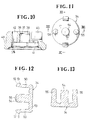
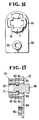
- the protruding portion 59 is cross-sectionally circular in shape and has a plurality of notches 61, 61 disposed around its periphery substantially in a criss-cross fashion as shown in Figure 16.
- the protruding portion 59 has a pair of resilient members 62, 62 extending transversely from one end to the other.
- Each resilient member 62 includes at an end thereof a projection 63 extending inwardly and an inwardly directed tapered surface 64.
- the plug body 58 includes at one end thereof an enlarged head 66 engageable with the retaining recess 37 of the socket body 33, a neck 67 adjacent to the head 66 at a barrel portion 68, a pair of projecting portions 69, 69 extending laterally and outwardly and at the other end a pair of projections 71 extending outwardly.
- the barrel portion 68 has a larger thickness than that of the neck 67.
- Each projecting portion 69 is provided with a tapered surface 70 at an end opposite, to the head 66 as illustrated in Figure 20.
- the projecting portion 69 and projections 71 define a recess 72 for receiving the projections 63 of the plug holder 57 so that the plug body 58 is securely retained in place in the plug holder 57.
- the plug body 58 includes a pair of elongated portions 73, 73 integrally formed and disposed perpendicularly to the projecting portions 69, 69.
- a plate member 74 to be mounted on the helmet body A.
- the plate member 74 has at its upper portion a retaining opening 75 for receiving the protruding portion 59 of the plug holder 57 and at its lower portion a screw hole 76 corresponding to the threaded hole 65 defined in the plate 60.
- the retaining opening 75 is similar in shape to the protruding portion 59 of the plug holder 57 and a plurality of small projections 77 are engageable with the notches 61 disposed around the periphery of the protruding portion 59.
- the helmet body A is provided substantially centrally with a hole for receiving the plug 32 and at its lower portion with a hole corresponding to the threaded hole 65.
- the protruding portion 59 is inserted into the hole with each projection 77 of the plate member 74 retained in each notch 61 of the protruding portion 59, and a screw 78 is threaded into the threaded hole 65 when the plug 32 is mounted on the helmet body A.
- the plug 32 is retained in the socket 31 by guiding the head 66 of the plug body 58 from the opening 39 defined by the guide members 40 of the socket 31.
- the head 66 passes through the opening 39 with the pair of guide members 40 resiliently deformed and allowed to provide a passage and thus retained in the retaining recess 37 of the socket 31.
- the plug 32 is fitted by snap action into the socket 31 by simply retaining the head 66 with the protrusion 38 of the retaining recess 37.
- the mouth guard B or the like can be secured to the helmet body A by a single step of operation, which would otherwise need be closed or opened in a tedious manner.
- the presser 34 is pushed in the direction shown in Figure 23 with each resilient member 50 of the presser 34 deforming inwardly.
- the plug body 58 is then retracted with the head 66 pressed by the edge of the push bar 54.
- the head 66 is released from the protrusion 38 of the retaining recess 37 simply by pushing the presser 34 so that the plug 32 is detached from the socket 31. This will eliminate the drawing action required in the prior art snap button.
- the plug 32 is secured to the helmet body A by the plate member 74 for use with another securing means.
- the plate member 74 includes a projection 79 at the lower side thereof, the projection 79 being adhesively retained in a hole 80 of the downwardly extending plate 60 of the plug holder 57.
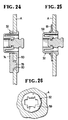
- Figure 25 shows another embodiment whereby the plug 32 is snap-fitted into a recess in the helmet body A with a push nut 81 by pushing the protruding portion 59 into the recess.
- the downwardly extending plate 60 of the plug 32, the plate member 74 or the like may be omitted if found preferable.
- Figure 26 shows another modified embodiment provided in Figure 25, in which the protruding portion 59 of the plug 32 is formed octagonal or in other suitable shape bind pressed into a circular hole in the helmet body A so as to retain the plug 32 in the helmet body A by a single step of operation against rotational movement, thus eliminating the need for the downwardly extending plate 60 or the plate member 74.
Landscapes
- Engineering & Computer Science (AREA)
- General Engineering & Computer Science (AREA)
- Physics & Mathematics (AREA)
- Electromagnetism (AREA)
- Structural Engineering (AREA)
- Mechanical Engineering (AREA)
- Helmets And Other Head Coverings (AREA)
Claims (12)
- Dispositif de fixation (30) pour une mentonnière (B) ou une visière (C) d'un casque (A), comprenant une pièce mâle (32) montée sur le casque (A) et une pièce femelle (31) montée sur la mentonnière (B) ou la visière (C), cactérisé en ce que la pièce mâle (32) comporte un support (57) de pièce mâle comprenant une paire d'éléments élastiques (62) s'étendant chacun de façon transversale vers l'intérieur du support de pièce mâle et un corps (58) de pièce mâle maintenu de façon amovible entre la paire d'éléments élastiques (62), ledit corps (58) de pièce mâle comprenant une tête (66) à son extrémité avant, et en ce que la pièce femelle (31) comprend un corps (33) de pièce femelle comportant une cavité de retenue (37) destinée à recevoir la tête (66) et un élément presseur (34) maintenu de façon amovible dans ladite cavité (37) du corps (33) de pièce femelle, l'élément presseur (34) comprenant une paire d'éléments élastiques (50) s'étendant dans le sens transversal depuis cet élément et une barre de poussée (54) adaptée pour libérer ladite tête (66) de la cavité de retenue (37) à l'encontre de la tension de la paire d'éléments élastiques (50).
- Dispositif de fixation (30) selon la revendication 1, caractérisé en ce que le corps (33) de pièce femelle comporte une ouverture (35) destinée à recevoir l'élément presseur (34).
- Dispositif de fixation (30) selon la revendication 1, caractérisé en ce que la cavité de retenue (37) comporte, à l'une de ses extrémités, une saillie circulaire (38) dirigée vers l'intérieur.
- Dispositif de fixation (30) selon la revendication 1, caractérisé en ce qu'une paire d'éléments de guidage (40, 40) sont disposés latéralement à l'endroit de la cavité de retenue (37).
- Dispositif de fixation (30) selon la revendication 1, caractérisé en ce que chaque paire de trous de guidage (41, 42) destinés à recevoir des barres de guidage (55, 56) et des évidements (43, 43) recevant de façon amovible l'élément presseur élastique (50) sont disposés dans une structure interne dudit corps (33) de pièce femelle.
- Dispositif de fixation (30) selon la revendication 1, caractérisé en ce qu'une pluralité d'éléments élastiques (46) sont disposés à la périphérie du corps (33) de pièce femelle comportant une saillie périphérique (47).
- Dispositif de fixation (30) selon la revendication 1, caractérisé en ce que l'élément presseur (34) comprend, en outre, une plaque de base (53) et une paire de barres de guidage (55, 56), ladite paire d'éléments élastiques (50) étant diamétralement opposés l'un à l'autre et s'étendant parallèlement à ladite plaque (53), chaque barre de guidage (55, 56) s'étendant parallèlement à ladite barre de poussée (54), chacun desdits éléments élastiques (50) ayant à l'une de ses extrémités une saillie (51) dirigée vers l'extérieur et comportant une partie diminuant d'épaisseur vers l'intérieur, et ladite barre de poussée (54) s'étendant depuis ladite plaque (53) avec laquelle elle fait corps centralement.
- Dispositif de fixation (30) selon la revendication 1, caractérisé en ce que chaque saillie (51) desdits éléments élastiques (50, 50) est retenue dans un trou de retenue (45) dudit corps (33) de pièce femelle.
- Dispositif de fixation (30) selon la revendication 1, caractérisé en ce que le corps (58) de pièce mâle comprend, à son extrémité avant, une tête agrandie (66), un col (67) adjacent à la tête (66) et une partie cylindrique (68), ladite partie cylindrique (68) comprenant une paire de portions saillantes latérales (69, 69) comportant chacune une surface inclinée (70) et à sa base une paire de saillies latérales (71, 71), ladite partie saillante (69) et ladite saillie latérale (71) définissant une cavité (72) destinée à recevoir une saillie (63) de ladite paire d'éléments élastiques (62), la partie cylindrique (68) comportant une paire de parties allongées (73, 73) diamétralement opposées, en travers de la partie saillante (69).
- Dispositif de fixation (30) selon la revendication 1, caractérisé en ce que le support (57) de pièce mâle comprend une partie saillante (59) à sa partie supérieure et une plaque (60) s'étendant vers le bas, ladite partie saillante (59) comportant une pluralité d'encoches (61) disposées sur sa périphérie de façon équidistante et étant polygonale, ladite paire d'éléments élastiques (62, 62) étant pourvue, à une extrémité, d'une saillie (63) ayant une surface inclinée (64).
- Dispositif de fixation (30) selon la revendication 10, caractérisé en ce que la plaque (60) s'étendant vers le bas porte contre un élément formant plaque (74) comportant une ouverture de retenue (75) dans sa partie supérieure et un trou (76, 80) dans sa partie inférieure, et l'ouverture de retenue (75) peut venir en prise libérable avec des encoches (61) dans ledit support (57) de pièce mâle, le trou (76, 80) pouvant être assemblé par vissage avec une vis ou assemblé à l'aide d'un adhésif avec une partie (79) s'étendant depuis ladite plaque (60).
- Dispositif de fixation (30) selon la revendication 11, caractérisé en ce que la partie saillante (59) est retenue dans un trou circulaire du corps (A) de casque par une action de blocage élastique avec des éléments de poussée (81, 81).
Applications Claiming Priority (2)
| Application Number | Priority Date | Filing Date | Title |
|---|---|---|---|
| JP285248/88 | 1988-11-11 | ||
| JP28524888A JPH064922B2 (ja) | 1988-11-11 | 1988-11-11 | ヘルメット用マウスガード等の固定具 |
Publications (2)
| Publication Number | Publication Date |
|---|---|
| EP0368360A1 EP0368360A1 (fr) | 1990-05-16 |
| EP0368360B1 true EP0368360B1 (fr) | 1993-06-23 |
Family
ID=17689035
Family Applications (1)
| Application Number | Title | Priority Date | Filing Date |
|---|---|---|---|
| EP19890120948 Expired - Lifetime EP0368360B1 (fr) | 1988-11-11 | 1989-11-11 | Dispositif pour fixer la mentonnière d'un casque |
Country Status (3)
| Country | Link |
|---|---|
| EP (1) | EP0368360B1 (fr) |
| JP (1) | JPH064922B2 (fr) |
| DE (1) | DE68907313T2 (fr) |
Families Citing this family (5)
| Publication number | Priority date | Publication date | Assignee | Title |
|---|---|---|---|---|
| DE9005887U1 (de) * | 1990-05-23 | 1991-09-19 | Veit Transpo GmbH, 8910 Landsberg | Fördermittel |
| JPH0569122U (ja) * | 1992-02-27 | 1993-09-17 | 吉田工業株式会社 | ヘルメット用マウスガード等の固定具 |
| JP2668322B2 (ja) * | 1993-07-19 | 1997-10-27 | 昭栄化工株式会社 | 乗車用ヘルメット |
| WO2016106749A1 (fr) * | 2014-12-31 | 2016-07-07 | 海能达通信股份有限公司 | Dispositif de fixation aisément désassemblé |
| FR3127534A1 (fr) * | 2021-09-27 | 2023-03-31 | Psa Automobiles Sa | Dispositif de fixation d’une pièce sur une structure porteuse |
Family Cites Families (11)
| Publication number | Priority date | Publication date | Assignee | Title |
|---|---|---|---|---|
| US1647781A (en) * | 1924-06-14 | 1927-11-01 | Carr Fastener Co Ltd | Fastener |
| US1760833A (en) * | 1926-07-23 | 1930-05-27 | United Carr Fastener Corp | Separable fastener |
| US1820323A (en) * | 1928-10-11 | 1931-08-25 | Delbert J Powell | Fastener |
| US2526791A (en) * | 1945-09-29 | 1950-10-24 | Frederick Archibald Pillet | Fastening device |
| CH268830A (it) * | 1946-08-02 | 1950-06-15 | Cappelletti Jolanda | Dispositivo di collegamento per cinture. |
| DE835357C (de) * | 1951-02-06 | 1952-03-31 | Knopf Und Metallwarenfabrik G | Schnalle mit Schieber |
| US3216023A (en) * | 1962-02-15 | 1965-11-09 | John T Riddell Inc | Jaw protector |
| GB1408667A (en) * | 1973-06-29 | 1975-10-01 | Dzus Fastener Europe | Quick release fastener |
| DE2846636C3 (de) * | 1978-10-26 | 1981-04-02 | Schuberth-Werk Gmbh & Co Kg, 3300 Braunschweig | Integralhelm |
| JPH046569Y2 (fr) * | 1986-05-15 | 1992-02-24 | ||
| DE8704449U1 (de) * | 1987-03-25 | 1987-05-07 | Römer GmbH, 7910 Neu-Ulm | Schutzhelm |
-
1988
- 1988-11-11 JP JP28524888A patent/JPH064922B2/ja not_active Expired - Lifetime
-
1989
- 1989-11-11 DE DE1989607313 patent/DE68907313T2/de not_active Expired - Fee Related
- 1989-11-11 EP EP19890120948 patent/EP0368360B1/fr not_active Expired - Lifetime
Also Published As
| Publication number | Publication date |
|---|---|
| EP0368360A1 (fr) | 1990-05-16 |
| JPH064922B2 (ja) | 1994-01-19 |
| DE68907313T2 (de) | 1994-01-27 |
| JPH02133603A (ja) | 1990-05-22 |
| DE68907313D1 (de) | 1993-07-29 |
Similar Documents
| Publication | Publication Date | Title |
|---|---|---|
| US5546610A (en) | Fastening system for fastening a face-protection sheild and/or hearing protection caps to a work helmet | |
| JPH0580311U (ja) | 紐類の抜止具 | |
| US3009248A (en) | Letter opener | |
| US4345848A (en) | Spectacle hinge pin | |
| EP0187113A2 (fr) | Dispositif de blocage de cordes | |
| CA2107247A1 (fr) | Dispositif de fixation a pression | |
| CA2058030A1 (fr) | Dispositif de montage du masque sur un casque | |
| EP0368360B1 (fr) | Dispositif pour fixer la mentonnière d'un casque | |
| USD455337S1 (en) | Cord fastener | |
| JPS62152909U (fr) | ||
| JPS6313222Y2 (fr) | ||
| US5546966A (en) | Hair clip | |
| US20040228678A1 (en) | Securing clip | |
| GB2264142A (en) | Clip | |
| CN219249432U (zh) | 一种指甲钳 | |
| JP3483206B2 (ja) | 支線ガード | |
| JPS6317849Y2 (fr) | ||
| KR900004489Y1 (ko) | 일회용 치솔 | |
| JPS643374Y2 (fr) | ||
| CN210094843U (zh) | 一种便于机器人抓取的无偏离可折断鞋楦 | |
| CN208403384U (zh) | 下巴扣 | |
| JPH03127812U (fr) | ||
| JPH0516173Y2 (fr) | ||
| JPH0333166U (fr) | ||
| JPH02110634U (fr) |
Legal Events
| Date | Code | Title | Description |
|---|---|---|---|
| PUAI | Public reference made under article 153(3) epc to a published international application that has entered the european phase |
Free format text: ORIGINAL CODE: 0009012 |
|
| AK | Designated contracting states |
Kind code of ref document: A1 Designated state(s): DE FR IT |
|
| 17P | Request for examination filed |
Effective date: 19900817 |
|
| 17Q | First examination report despatched |
Effective date: 19920213 |
|
| GRAA | (expected) grant |
Free format text: ORIGINAL CODE: 0009210 |
|
| AK | Designated contracting states |
Kind code of ref document: B1 Designated state(s): DE FR IT |
|
| ITF | It: translation for a ep patent filed | ||
| REF | Corresponds to: |
Ref document number: 68907313 Country of ref document: DE Date of ref document: 19930729 |
|
| ET | Fr: translation filed | ||
| PLBE | No opposition filed within time limit |
Free format text: ORIGINAL CODE: 0009261 |
|
| STAA | Information on the status of an ep patent application or granted ep patent |
Free format text: STATUS: NO OPPOSITION FILED WITHIN TIME LIMIT |
|
| 26N | No opposition filed | ||
| PGFP | Annual fee paid to national office [announced via postgrant information from national office to epo] |
Ref country code: FR Payment date: 19940923 Year of fee payment: 6 |
|
| PGFP | Annual fee paid to national office [announced via postgrant information from national office to epo] |
Ref country code: DE Payment date: 19941031 Year of fee payment: 6 |
|
| ITPR | It: changes in ownership of a european patent |
Owner name: CAMBIO RAGIONE SOCIALE;YKK CORPORATION |
|
| REG | Reference to a national code |
Ref country code: FR Ref legal event code: CD |
|
| PG25 | Lapsed in a contracting state [announced via postgrant information from national office to epo] |
Ref country code: FR Effective date: 19960731 |
|
| PG25 | Lapsed in a contracting state [announced via postgrant information from national office to epo] |
Ref country code: DE Effective date: 19960801 |
|
| REG | Reference to a national code |
Ref country code: FR Ref legal event code: ST |
|
| PG25 | Lapsed in a contracting state [announced via postgrant information from national office to epo] |
Ref country code: IT Free format text: LAPSE BECAUSE OF NON-PAYMENT OF DUE FEES;WARNING: LAPSES OF ITALIAN PATENTS WITH EFFECTIVE DATE BEFORE 2007 MAY HAVE OCCURRED AT ANY TIME BEFORE 2007. THE CORRECT EFFECTIVE DATE MAY BE DIFFERENT FROM THE ONE RECORDED. Effective date: 20051111 |