EP0368385A2 - Einrichtung zur Einstellung des Werkzeuges einer Autoreifenmontier- und -demontiermaschine - Google Patents
Einrichtung zur Einstellung des Werkzeuges einer Autoreifenmontier- und -demontiermaschine Download PDFInfo
- Publication number
- EP0368385A2 EP0368385A2 EP89202717A EP89202717A EP0368385A2 EP 0368385 A2 EP0368385 A2 EP 0368385A2 EP 89202717 A EP89202717 A EP 89202717A EP 89202717 A EP89202717 A EP 89202717A EP 0368385 A2 EP0368385 A2 EP 0368385A2
- Authority
- EP
- European Patent Office
- Prior art keywords
- rod
- arm
- tool
- stop
- wheel
- Prior art date
- Legal status (The legal status is an assumption and is not a legal conclusion. Google has not performed a legal analysis and makes no representation as to the accuracy of the status listed.)
- Granted
Links
Images

Classifications
-
- B—PERFORMING OPERATIONS; TRANSPORTING
- B60—VEHICLES IN GENERAL
- B60B—VEHICLE WHEELS; CASTORS; AXLES FOR WHEELS OR CASTORS; INCREASING WHEEL ADHESION
- B60B30/00—Means for holding wheels or parts thereof
- B60B30/06—Means for holding wheels or parts thereof engaging the wheel body, e.g. the rim
-
- B—PERFORMING OPERATIONS; TRANSPORTING
- B60—VEHICLES IN GENERAL
- B60C—VEHICLE TYRES; TYRE INFLATION; TYRE CHANGING; CONNECTING VALVES TO INFLATABLE ELASTIC BODIES IN GENERAL; DEVICES OR ARRANGEMENTS RELATED TO TYRES
- B60C25/00—Apparatus or tools adapted for mounting, removing or inspecting tyres
- B60C25/01—Apparatus or tools adapted for mounting, removing or inspecting tyres for removing tyres from or mounting tyres on wheels
- B60C25/05—Machines
- B60C25/132—Machines for removing and mounting tyres
Definitions
- the invention relates to a device for adjusting the distance between a wheel fixed on a rotary table and the tool of an apparatus for mounting and dismounting an automobile tire respectively on and from said wheel.
- Apparatuses for mounting and dismounting automobile tires are known, which are mainly composed of a base, provided in its front part with a rotary horizontal table on which the wheel is fixed, and provided in its rear part with a vertical column tilting backwards, which column is provided in its upper part with a horizontally displaceable arm, at the end of which a vertical rod can move and carrying at its lower end the tool for mounting and dismounting d '' a tire on and of the aforementioned wheel, the horizontal arm being provided with a lever clamping means capable of fixing the vertical rod in the horizontal arm and the latter in the vertical column while providing a vertical and horizontal distance from the tool relative to said wheel.
- a vertical column fixedly mounted on the rear of the base, while on the front part of the base is mounted a rotary table which holds the wheel, and in order to adjust the distance between said wheel and the tool for mounting and dismounting the tire and to limit the movement of the arm and of the rod carrying the tool, in the direction of the wheel, it is mounted on the rear end of the arm an adjustable stop and a blocking means for fixing this adjustable stop which acts freely with a fixed stop of the column, and where between said blocking means and the lever clamping means for fixing in the arm the rod carrying the tool, there is provided a coupling means.
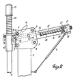
- a rotary table 2 horizontal, actuated by a motor, which table is provided with claws 3 radially displaceable, between which a wheel 4 is clamped.
- a vertical column 5 which is provided at the top with a conductive box 6.
- this conductive box is disposed between four guide rollers 7 an arm 8 freely movable and descending obliquely towards the wheel.
- a gas spring 9 is mounted between the rear end of the arm 8 and the column 5.
- the front part of the arm 8 is provided with a sleeve 10, in which a vertical rod 11 slides freely, the lower part of which carries the tool 12 for mounting and dismounting a tire.
- the top of the rod 11 is provided with a handle 13.
- a clamping plate 14 disposed around the rod 11, which clamping plate 14 is able to a guide bolt 15, which is freely movable in an eyelet 16, which is part of the sleeve 10.
- the clamping plate 14 is obliquely pushed into the locking position on the vertical rod 11 by a pressure stud 17 provided in the arm 8 and pushed upwards by an eccentric 18 mounted in the arm 8, eccentric on which a control lever 19 is fixed.
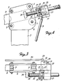
- a guide block 21 On the rear end of the arm 8 is mounted a guide block 21, in which a rod stop 22 can freely slide parallel to the arm 8.
- a clamping plate 23 Around the stop rod 22 is provided a clamping plate 23, one side of which can slide freely on two guide bolts 24 and take an oblique position relative to the rod 22, which bolts 24 are fixed in the guide block 21.
- the opposite side of the clamping plate 23 is held against a pressure roller 25 by a pressure spring 26 placed between a collar of the head of the stop rod 22 and the clamping plate 23.
- the pressure roller 25 is mounted on an axis 27, which is fixed eccentrically on one of the end surfaces of a rotary cylinder 28 passing through the rear end of the arm 8.
- the cylinder 28 On the other end surface of the cylinder 28 is eccentrically fixed t an axis 29, which carries one of the ends of a coupling rod 30, while the other end of this rod 30 is fixed in the same way to the eccentric 18 of the clamping means for fixing the rod 11.
- the cylinder 28 To limit the rotation of the cylinder 28 in both directions, the cylinder 28 is provided with two pins 31-32, which act in concert with the stop 33 fixed on the arm 8.
- the stop rod 22 operates in concert with a stop 34 fixed on the conductive box 6 of the column 5, whereby it is possible to limit the movement of the arm 8 towards the wheel 4.
- the handle 19 is tilted forward, so that the eccentric 18 pushes the pressure pin 17 upwards and that the latter presses the pressure plate 14 obliquely on the rod 11, which slightly raises the latter while blocking it with respect to the sleeve 10.
Landscapes
- Engineering & Computer Science (AREA)
- Mechanical Engineering (AREA)
- Vehicle Cleaning, Maintenance, Repair, Refitting, And Outriggers (AREA)
- Straightening Metal Sheet-Like Bodies (AREA)
Applications Claiming Priority (2)
| Application Number | Priority Date | Filing Date | Title |
|---|---|---|---|
| BE8801274 | 1988-11-08 | ||
| BE8801274A BE1002584A6 (fr) | 1988-11-08 | 1988-11-08 | Dispositif pour ajuster l'outil d'un appareil de montage et de demontage de pneus d'automobiles. |
Publications (3)
| Publication Number | Publication Date |
|---|---|
| EP0368385A2 true EP0368385A2 (de) | 1990-05-16 |
| EP0368385A3 EP0368385A3 (en) | 1990-07-18 |
| EP0368385B1 EP0368385B1 (de) | 1992-12-02 |
Family
ID=3883712
Family Applications (1)
| Application Number | Title | Priority Date | Filing Date |
|---|---|---|---|
| EP19890202717 Expired - Lifetime EP0368385B1 (de) | 1988-11-08 | 1989-10-27 | Einrichtung zur Einstellung des Werkzeuges einer Autoreifenmontier- und -demontiermaschine |
Country Status (3)
| Country | Link |
|---|---|
| EP (1) | EP0368385B1 (de) |
| BE (1) | BE1002584A6 (de) |
| DE (1) | DE68903741T2 (de) |
Cited By (3)
| Publication number | Priority date | Publication date | Assignee | Title |
|---|---|---|---|---|
| EP0499825A1 (de) * | 1991-02-19 | 1992-08-26 | STAHLGRUBER Otto Gruber GmbH & Co. | Demontiervorrichtung für KFZ-Luftreifen |
| EP0572064A1 (de) * | 1992-05-27 | 1993-12-01 | du Quesne, Francis | Einstellvorrichtung eines Reifenhebels von einem Reifenwechselgerät |
| CN102795065A (zh) * | 2011-05-20 | 2012-11-28 | 古丽亚诺集团股份公司 | 一种用于安装和拆卸车辆轮胎的机器 |
Family Cites Families (4)
| Publication number | Priority date | Publication date | Assignee | Title |
|---|---|---|---|---|
| FR1053032A (fr) * | 1952-03-25 | 1954-01-29 | Appareil pour le démontage des pneumatiques | |
| BE764970A (fr) * | 1971-03-30 | 1971-08-16 | Duquesne Victor | Dispositif pour le montage et le demontage des pneus equipant les rouesdes vehicules automobiles. |
| BE852397A (fr) * | 1977-03-14 | 1977-07-01 | Victor Duquesne | Appareil pour mettre en place et enlever un pneu d'automobile |
| US4765387A (en) * | 1987-02-02 | 1988-08-23 | Fmc Corporation | Tire changer safety foot |
-
1988
- 1988-11-08 BE BE8801274A patent/BE1002584A6/fr not_active IP Right Cessation
-
1989
- 1989-10-27 EP EP19890202717 patent/EP0368385B1/de not_active Expired - Lifetime
- 1989-10-27 DE DE1989603741 patent/DE68903741T2/de not_active Expired - Fee Related
Cited By (5)
| Publication number | Priority date | Publication date | Assignee | Title |
|---|---|---|---|---|
| EP0499825A1 (de) * | 1991-02-19 | 1992-08-26 | STAHLGRUBER Otto Gruber GmbH & Co. | Demontiervorrichtung für KFZ-Luftreifen |
| EP0572064A1 (de) * | 1992-05-27 | 1993-12-01 | du Quesne, Francis | Einstellvorrichtung eines Reifenhebels von einem Reifenwechselgerät |
| CN102795065A (zh) * | 2011-05-20 | 2012-11-28 | 古丽亚诺集团股份公司 | 一种用于安装和拆卸车辆轮胎的机器 |
| JP2012240673A (ja) * | 2011-05-20 | 2012-12-10 | Giuliano Group Spa | 車両用のホイールタイヤを取り付けおよび取り外しするための機械 |
| CN102795065B (zh) * | 2011-05-20 | 2015-01-21 | 古丽亚诺集团股份公司 | 一种用于安装和拆卸车辆轮胎的机器 |
Also Published As
| Publication number | Publication date |
|---|---|
| DE68903741D1 (de) | 1993-01-14 |
| EP0368385B1 (de) | 1992-12-02 |
| EP0368385A3 (en) | 1990-07-18 |
| BE1002584A6 (fr) | 1991-04-02 |
| DE68903741T2 (de) | 1993-06-24 |
Similar Documents
| Publication | Publication Date | Title |
|---|---|---|
| EP0387460A1 (de) | Vorrichtung zum Auf- und Abmontieren von Ventilen und zum Schleifen von Ventilsitzen | |
| FR2956851A1 (fr) | Dispositif de manutention pour la manipulation d'objets lourds | |
| EP1142753B1 (de) | Kopfstütze, insbesondere für Kraftfahrzeugsitze | |
| FR2610251A1 (fr) | Appareil de securite pour protection contre l'eclatement dans une machine de changement de pneumatique | |
| BE1011494A3 (fr) | Dispositif auxiliaire pour le montage et le demontage d'un pneu. | |
| EP0368385B1 (de) | Einrichtung zur Einstellung des Werkzeuges einer Autoreifenmontier- und -demontiermaschine | |
| CH599865A5 (en) | Tyre removal and fitting machine | |
| BE1006846A6 (fr) | Dispositif pour ajuster l'outil d'un appareil de montage et de demontage de pneus d'automobiles. | |
| FR2472503A1 (fr) | Dispositif porte-velo | |
| FR2711346A1 (fr) | Dispositif de fixation d'une moto sur un socle et banc d'essai équipé d'un tel dispositif. | |
| FR2464172A2 (fr) | Support inclinable perfectionne notamment pour voiture d'enfant | |
| FR3004480A1 (fr) | Structure pliable de travail en encorbellement integrant un dispositif d'aide au depliage d'un auvent | |
| BE1007626A6 (fr) | Dispositif pour assister efficacement les operations de montage et de demontage d'un pneu d'une jante de roue. | |
| FR2689959A1 (fr) | Pied d'accorage muni d'un verrou. | |
| EP0628447A1 (de) | Gelenkbeschlag für Fahrzeugsitz | |
| FR2796344A1 (fr) | Mecanisme d'ancrage et d'articulation, notamment pour un siege arriere d'un vehicule automobile | |
| FR2695843A1 (fr) | Support universel de peinture, notamment pour éléments de carrosserie automobile. | |
| FR2794419A1 (fr) | Ensemble de colonne de direction | |
| EP1488848B1 (de) | System für das elastische Halten eines Behälters in Bezug auf einen Mischkopf eines Mischers | |
| FR2493119A1 (fr) | Siege pour travail debout | |
| EP1488849B1 (de) | Höhenverstellbare Mischer mit selbst blockier Einheit | |
| EP0006673B1 (de) | Einstellmechanismus für den werkzeughaltenden Arm einer Vorrichtung zum Aufziehen und Abnehmen eines Autoreifens | |
| EP0126436A1 (de) | Vorrichtung zur Einstellung eines Schraubstockes auf der Fussplatte eines Säulenbohrständers | |
| FR2509249A1 (fr) | Pedale de bicyclette permettant l'accrochage d'une chaussure en position prereglee | |
| CH681870A5 (de) |
Legal Events
| Date | Code | Title | Description |
|---|---|---|---|
| PUAI | Public reference made under article 153(3) epc to a published international application that has entered the european phase |
Free format text: ORIGINAL CODE: 0009012 |
|
| AK | Designated contracting states |
Kind code of ref document: A2 Designated state(s): BE CH DE ES FR GB IT LI NL |
|
| PUAL | Search report despatched |
Free format text: ORIGINAL CODE: 0009013 |
|
| AK | Designated contracting states |
Kind code of ref document: A3 Designated state(s): BE CH DE ES FR GB IT LI NL |
|
| 17P | Request for examination filed |
Effective date: 19901227 |
|
| 17Q | First examination report despatched |
Effective date: 19920408 |
|
| GRAA | (expected) grant |
Free format text: ORIGINAL CODE: 0009210 |
|
| AK | Designated contracting states |
Kind code of ref document: B1 Designated state(s): BE CH DE ES FR GB IT LI NL |
|
| PG25 | Lapsed in a contracting state [announced via postgrant information from national office to epo] |
Ref country code: NL Effective date: 19921202 Ref country code: ES Free format text: THE PATENT HAS BEEN ANNULLED BY A DECISION OF A NATIONAL AUTHORITY Effective date: 19921202 |
|
| REF | Corresponds to: |
Ref document number: 68903741 Country of ref document: DE Date of ref document: 19930114 |
|
| ITF | It: translation for a ep patent filed | ||
| GBT | Gb: translation of ep patent filed (gb section 77(6)(a)/1977) |
Effective date: 19930312 |
|
| NLV1 | Nl: lapsed or annulled due to failure to fulfill the requirements of art. 29p and 29m of the patents act | ||
| PLBE | No opposition filed within time limit |
Free format text: ORIGINAL CODE: 0009261 |
|
| STAA | Information on the status of an ep patent application or granted ep patent |
Free format text: STATUS: NO OPPOSITION FILED WITHIN TIME LIMIT |
|
| PG25 | Lapsed in a contracting state [announced via postgrant information from national office to epo] |
Ref country code: LI Effective date: 19931031 Ref country code: CH Effective date: 19931031 |
|
| 26N | No opposition filed | ||
| REG | Reference to a national code |
Ref country code: CH Ref legal event code: PL |
|
| PGFP | Annual fee paid to national office [announced via postgrant information from national office to epo] |
Ref country code: GB Payment date: 20001003 Year of fee payment: 12 |
|
| PGFP | Annual fee paid to national office [announced via postgrant information from national office to epo] |
Ref country code: FR Payment date: 20001027 Year of fee payment: 12 |
|
| PGFP | Annual fee paid to national office [announced via postgrant information from national office to epo] |
Ref country code: BE Payment date: 20001030 Year of fee payment: 12 |
|
| PGFP | Annual fee paid to national office [announced via postgrant information from national office to epo] |
Ref country code: DE Payment date: 20001228 Year of fee payment: 12 |
|
| PG25 | Lapsed in a contracting state [announced via postgrant information from national office to epo] |
Ref country code: GB Free format text: LAPSE BECAUSE OF NON-PAYMENT OF DUE FEES Effective date: 20011027 |
|
| PG25 | Lapsed in a contracting state [announced via postgrant information from national office to epo] |
Ref country code: BE Free format text: LAPSE BECAUSE OF NON-PAYMENT OF DUE FEES Effective date: 20011031 |
|
| REG | Reference to a national code |
Ref country code: GB Ref legal event code: IF02 |
|
| BERE | Be: lapsed |
Owner name: DU QUESNE FRANCIS Effective date: 20011031 |
|
| GBPC | Gb: european patent ceased through non-payment of renewal fee |
Effective date: 20011027 |
|
| PG25 | Lapsed in a contracting state [announced via postgrant information from national office to epo] |
Ref country code: FR Free format text: LAPSE BECAUSE OF NON-PAYMENT OF DUE FEES Effective date: 20020628 |
|
| PG25 | Lapsed in a contracting state [announced via postgrant information from national office to epo] |
Ref country code: DE Free format text: LAPSE BECAUSE OF NON-PAYMENT OF DUE FEES Effective date: 20020702 |
|
| REG | Reference to a national code |
Ref country code: FR Ref legal event code: ST |
|
| PG25 | Lapsed in a contracting state [announced via postgrant information from national office to epo] |
Ref country code: IT Free format text: LAPSE BECAUSE OF NON-PAYMENT OF DUE FEES Effective date: 20051027 |